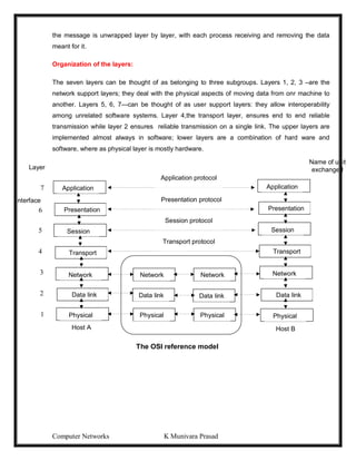
This document provides lecture notes on computer networks. It begins with an introduction to computer networks, defining them as interconnected autonomous computers that exchange information. It then discusses network models including the OSI reference model, which structures network communication across seven layers of abstraction. The document outlines the key concepts covered in each of the five units of an undergraduate course on computer networks.


![Computer Networks K Munivara Prasad
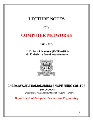
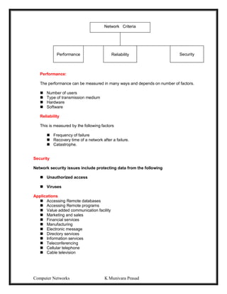
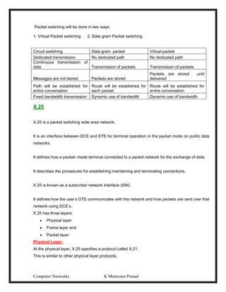
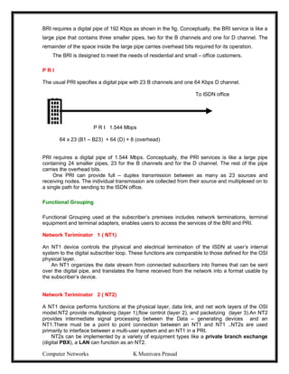
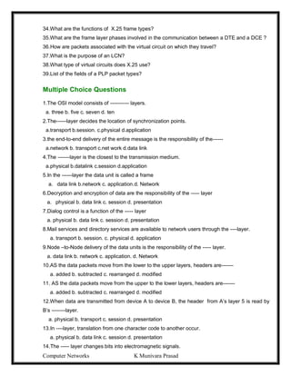
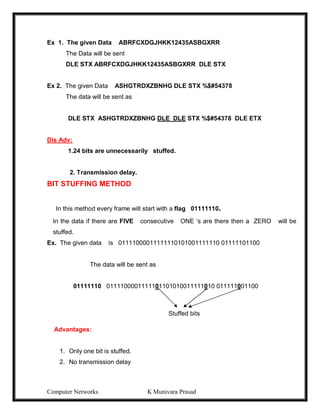
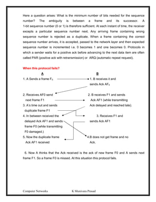
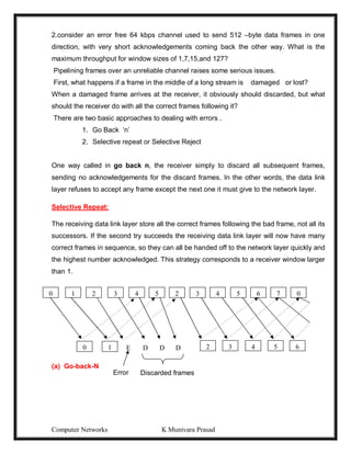
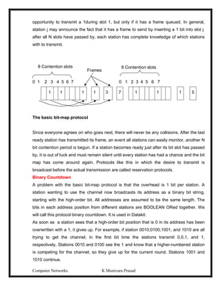
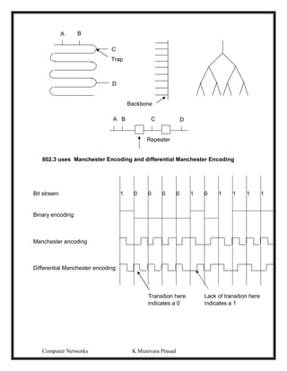
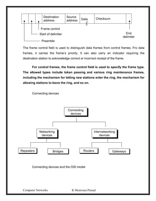
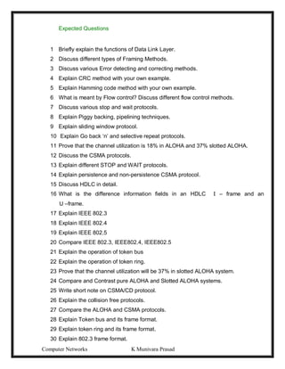
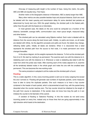
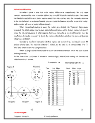
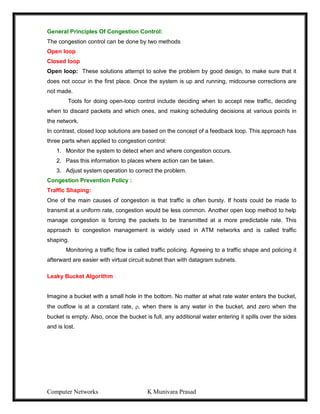
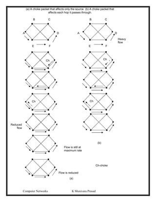
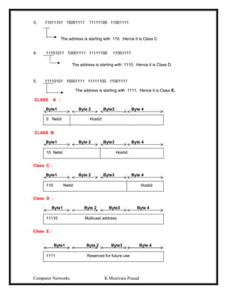
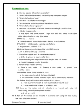
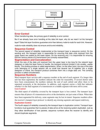
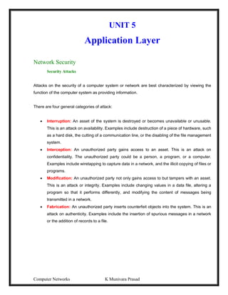
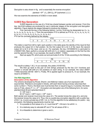
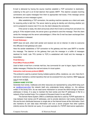
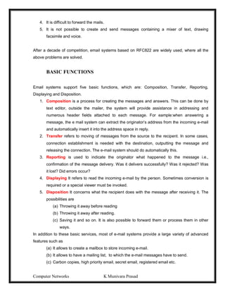
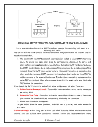
The Vertical Redundancy Check (VRC) and the Parity check character is referred to as
the Longitudinal Redundancy Check (LRC).
1 0 1 1 0 1 1 1
1 1 0 1 0 1 1 1
0 0 1 1 1 0 1 0
1 1 1 1 0 0 0 0
1
0 0 0 1 0 1 1
0 1 0 1 1 1 1 1
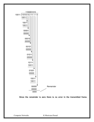
CRC Method
1. The frame is expressed in the form of a Polynomial F(x).0 1 1 1 1 1 1 0
2. Both the sender and receiver will agree upon a generator polynomial G(x) in
advance.
3. Let ‘r’ be the degree of G(x).Append ‘r’ zero bits to the lower – order end of
frame now it contains m+r bits.
4. Divide the bit string by G(x) using Mod 2 operation.
5. Transmitted frame [T(x)] = frame + remainder
6. Divide T(x) by G(x) at the receiver end. If the result is a zero, then the frame is
transmitted correctly. Ex. Frame: 1101011011
Generator: 10011
Message after appending 4 zero bits: 11010110000
b21
bn1 R1
b22
bnm
c1
cn
bn2 R2
Rm
cn+1
bit
1
bit
2
bit
n
Parity
bit
Character 1
Character 2
Character m
Parity check
character
LRC
VRC
b11
b1m
b12
c2
b2m bnm](https://image.slidesharecdn.com/computernetwrks-210426072133/85/Computer-netwrks-32-320.jpg)


![Computer Networks K Munivara Prasad
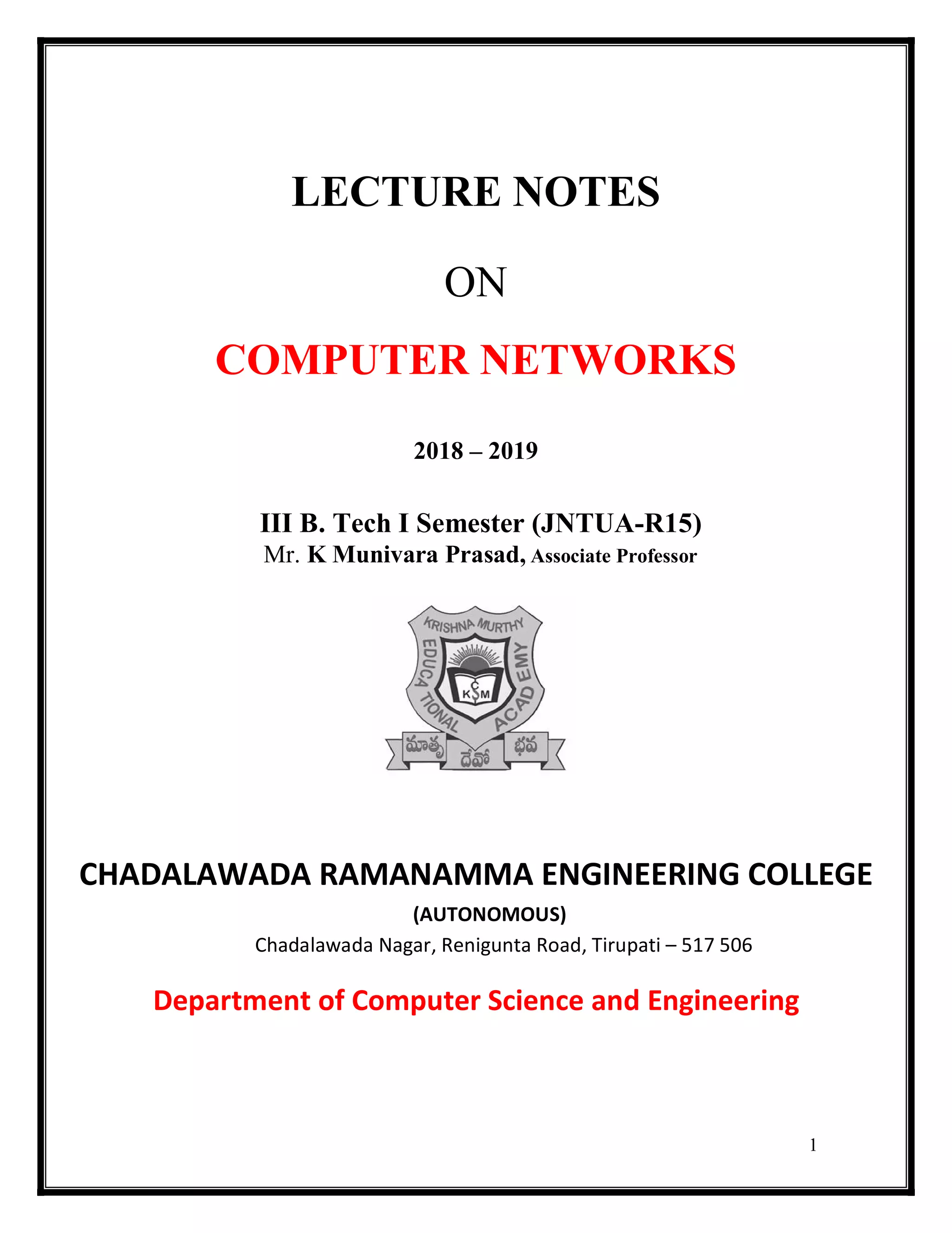
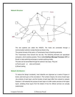
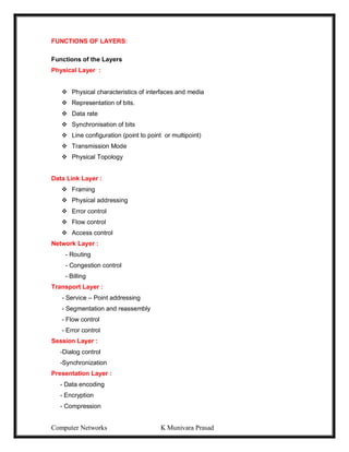
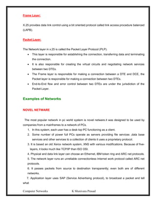
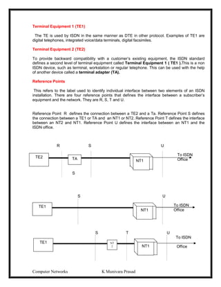
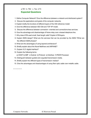
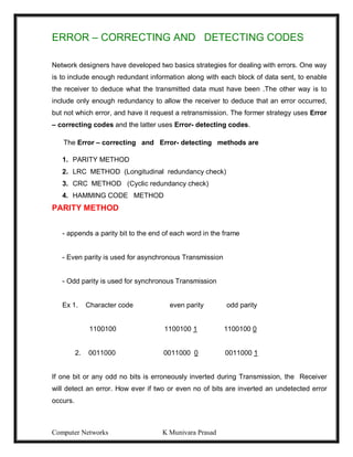
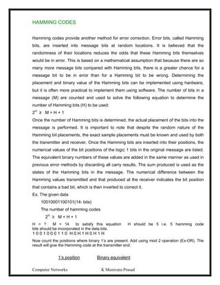
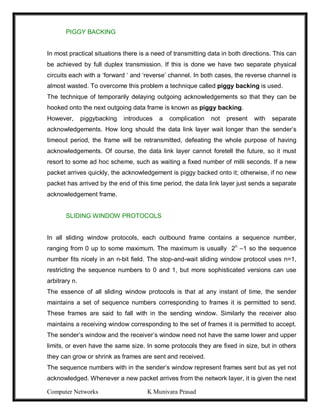
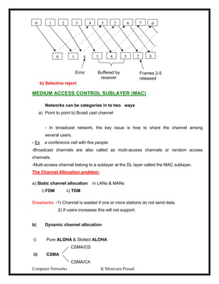
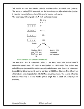
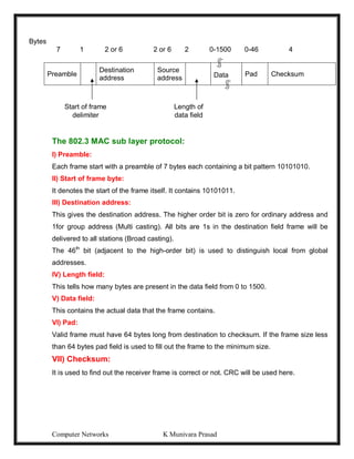
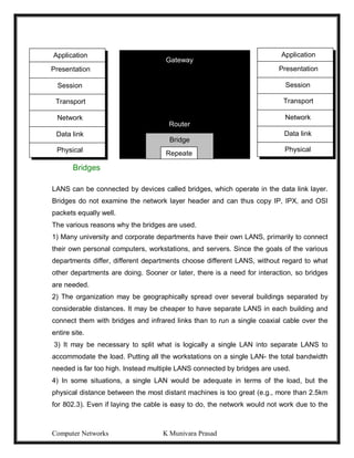
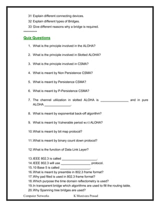
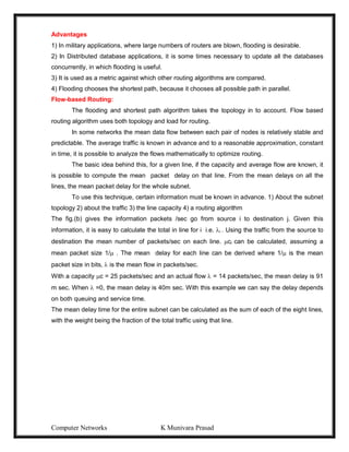
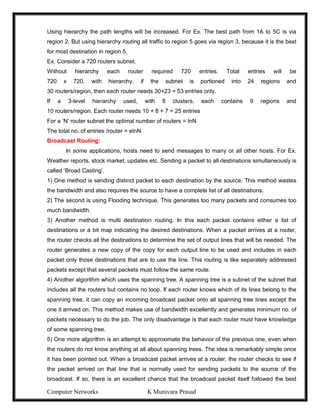
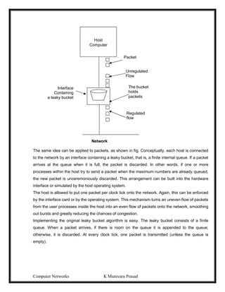
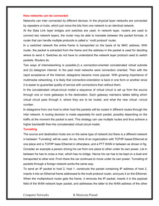
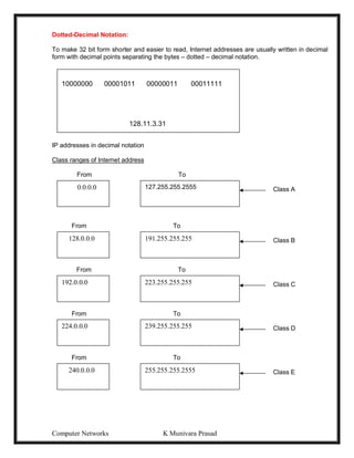
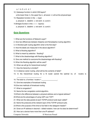
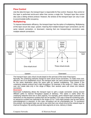
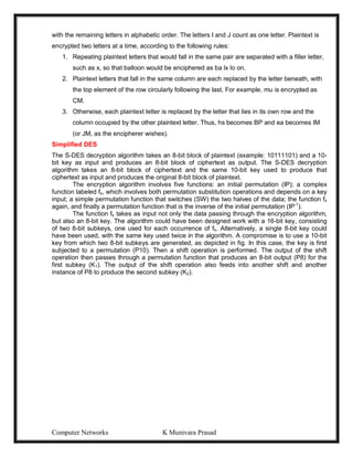
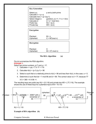
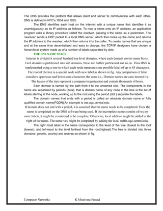
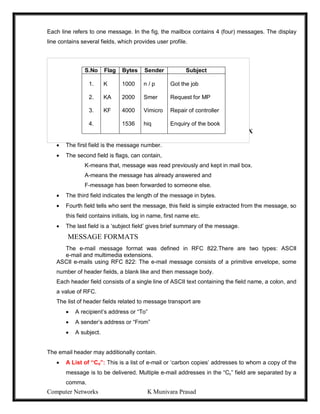
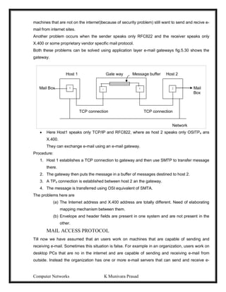
Pure ALOHA
-1970’s Norman Abramson end his colleagues devised this method, used ground –based
radio broad costing. This is called the ALOHA system.
-The basic idea, many users are competing for the use of a single shared channel.
-There are two versions of ALOHA: Pure and Slotted.
-Pure ALOHA does not require global time synchronization, where as in slotted ALOHA
the time is divided into discrete slots into which all frames must fit.
-Let users transmit whenever they have data to be sent.
-There will be collisions and all collided frames will be damaged.
-Senders will know through feedback property whether the frame is destroyed or not by
listening channel.
[-With a LAN it is immediate, with a satellite, it will take 270m sec.]
-If the frame was destroyed, the sender waits random amount of time and again sends
the frame.
-The waiting time must be random otherwise the same frame will collide over and over.
USER
A
B
C
D
TIME](https://image.slidesharecdn.com/computernetwrks-210426072133/85/Computer-netwrks-46-320.jpg)
![Computer Networks K Munivara Prasad
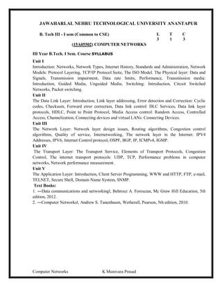
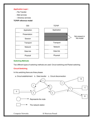
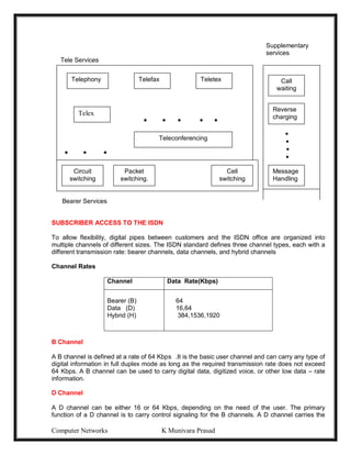
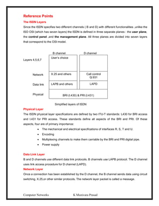
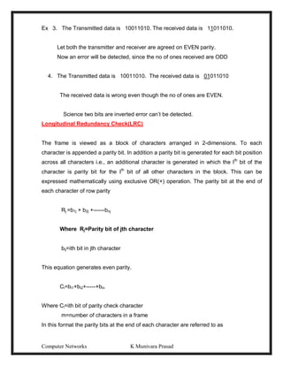
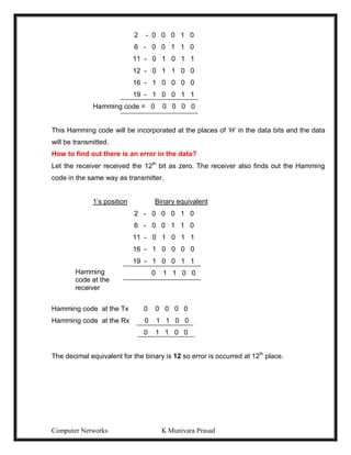
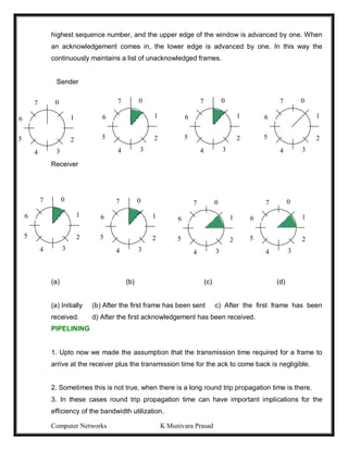
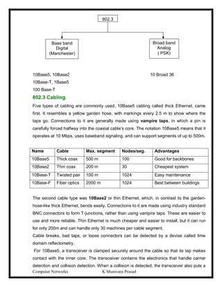
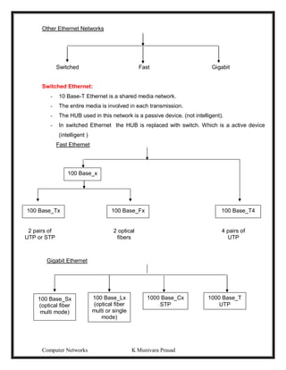
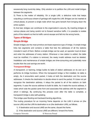
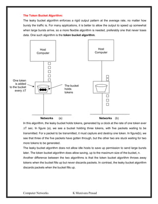
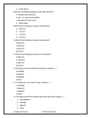
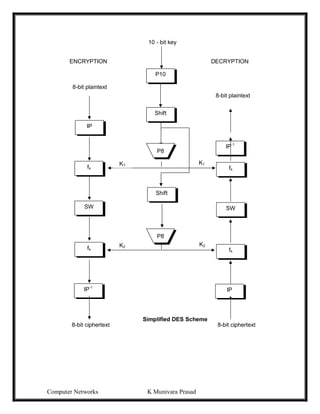
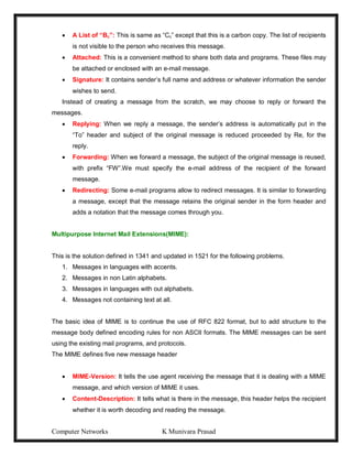
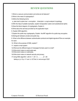
Frames are transmitted at completely arbitrary times
-Whenever two frames try to occupy the channel at the same time, there will be a collision
and both will be destroyed.
-We have to find out what is the efficiency of an ALOHA channel?
-Let us consider an infinite collection of interactive users sitting at their systems (stations).
-A user will always in two states typing or waiting.
-Let the ‘Frame time’ denotes the time required to transmit one fixed length frame.
-Assume that infinite populations of users are generating new frames according to
possion distribution with mean N frames per frame time.
-If N>1 users are generating frames at a higher rate than the channel can handle.
-For reasonable throughput 0<N<1.
-In addition to new frames, the station also generates retransmission of frames.
-Old and new frames are G per frame time.
-G> N
-At low load there will be few collisions, so G ~ N
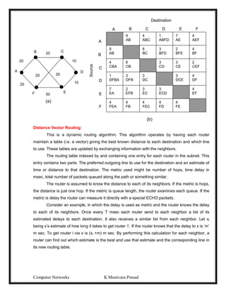
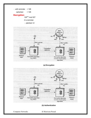
-Under all loads, the throughput S = GPo, where Po is the probability that a frame does not
suffer a collision.
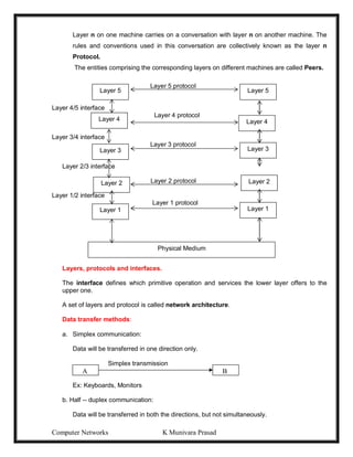
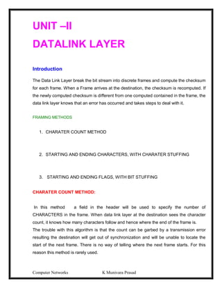
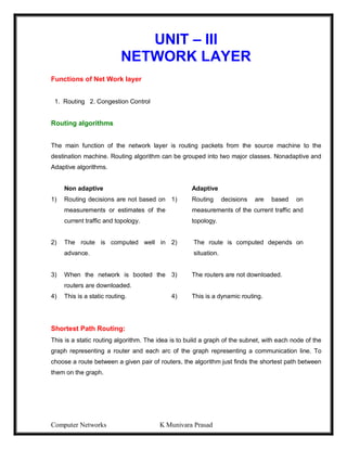
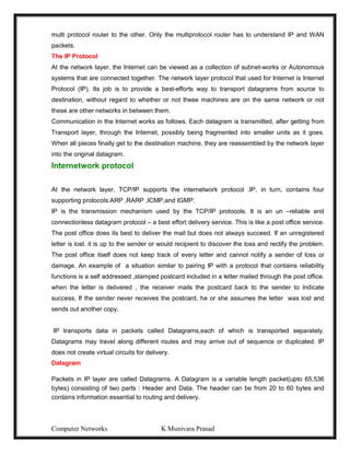
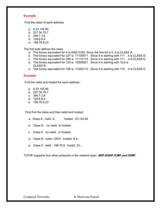
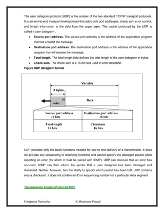
-A frame will not suffer a collision if no other frames are sent with one frame time of its
start.
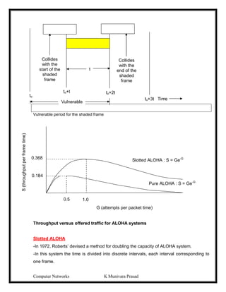
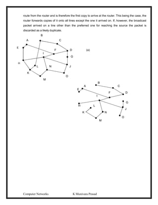
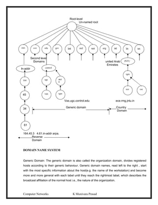
-Let ‘t’ be the time required to send a frame.
-If any other user has generated a frame between time to and to+t, the end of that frame
will collide with the beginning of the shaded frame.
-Similarly, any other frame started b/w to+t and to+2t will bump into the end of the shaded
frame.
-The probability that ‘k’ frames are generated during a given frame time is given by the
possion distribution:
Pr[k] = Gk
e-G
k!
-The probability of zero frames is just e-G
-In an interval two frame times long, the mean number at frames generated is 2G.
-The probability at no other traffic being initiated during the entire vulnerable period is
given by
Po = e-2G
S= Ge-2G
[S=GPo]
The Maximum through put occurs at G=0.5 with S=1/2e = 0.184
The channel utilization at pure ALOHA =18%.](https://image.slidesharecdn.com/computernetwrks-210426072133/85/Computer-netwrks-47-320.jpg)

![Computer Networks K Munivara Prasad
[0,2*max-propagation_delay] before retransmitting its packet. If the retransmission also
fails, then the station backs off for a random time in the interval [0,4*
max_propagation_delay], and tries again. Each subsequent collision doubles the backoff
interval length, until the retransmission finally succeeds. On a successful transmission,
the backoff interval is reset to the initial value. We call this type of backoff exponential
backoff.
CSMA/CA
In many wireless LANS, unlike wired LANS, the station has no idea whether the packet
collided with another packet or not until it receives an acknowledgement from receiver. In
this situation, collisions have a greater effect on performance than with CSMA/CD, where
colliding packets can be quickly detected and aborted. Thus, it makes sense to try to
avoid collisions, if possible. CSMA/CA is basically p-persistence, with the twist that when
the medium becomes idle, a station must wait for a time called the interframe spacing or
IFS before contending for a slot. A station gets a higher priority if it is allocated smaller
inter frame spacing.
When a station wants to transmit data, it first checks if the medium is busy. If it is, it
continuously senses the medium, waiting for it to become idle. When the medium
becomes idle, the station first waits for an interframe spacing corresponding to its priority
level, then sets a contention timer to a time interval randomly selected in the range
[0,CW], where CW is a predefined contention window length. When this timer expires, it
transmits a packet and waits for the receiver to send an ack. If no ack is received, the
packet is assumed lost to collision, and the source tries again, choosing a contention
timer at random from an interval twice as long as the one before(binary exponential
backoff). If the station senses that another station has begun transmission while it was
waiting for the expiration of the contention timer, it does not reset its timer, but merely
freezer it, and restarts the countdown when the packet completes transmission. In this
way, stations that happen to choose a longer timer value get higher priority in the next
round of contention.
Collision-Free Protocols
A Bit-Map Protocol
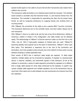
In the basic bit-map method, each contention period consists of exactly N slots. If station
0 has a frame to send, it transmits a 1 bit during the zeroth slot. No other station is
allowed to transmit during this slot. Regardless of what station 0 does, station 1 gets the](https://image.slidesharecdn.com/computernetwrks-210426072133/85/Computer-netwrks-51-320.jpg)


![Computer Networks K Munivara Prasad
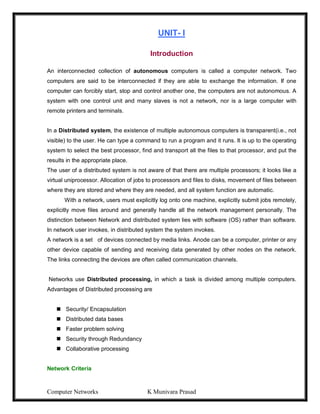
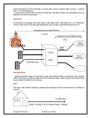
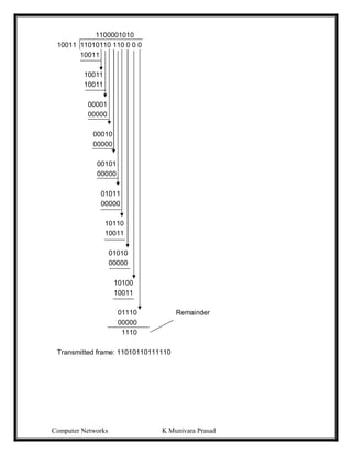
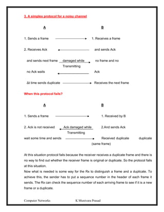
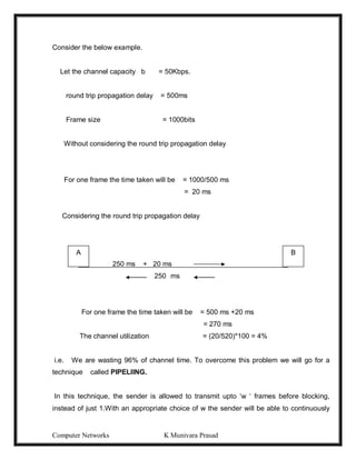
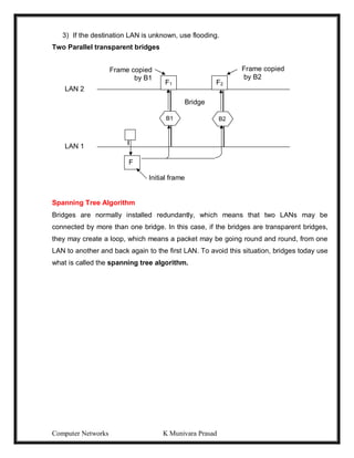
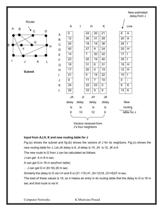
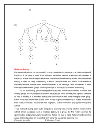
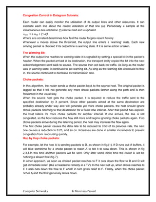
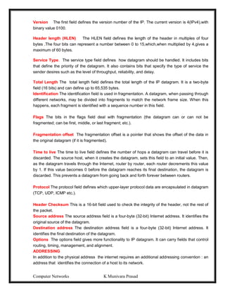
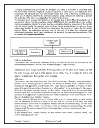
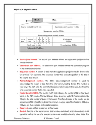
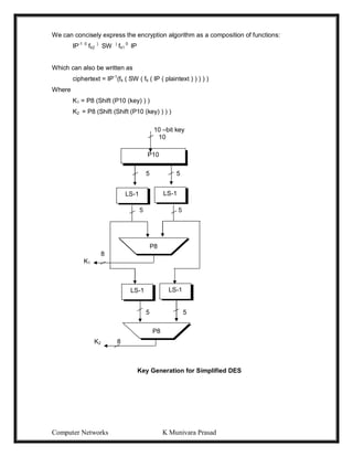
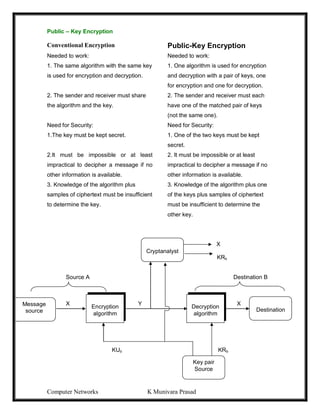
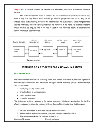
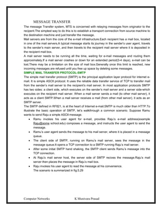
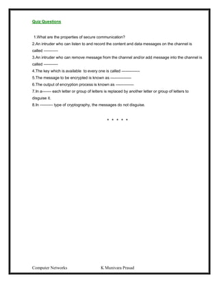
Information Information
Source destination
(a) Normal flow
(b) Interruption (C) Interception
(d) Modification (e) Fabrication
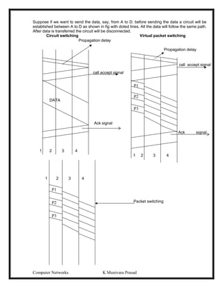
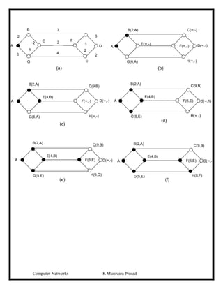
CONVENTIONAL ENCRYPTION MODEL
The original intelligible message, referred to as plaintext, is converted into apparently
random nonsense, referred to as ciphertext. The encryption process consists of an algorithm and
a key. The key is a value independent of the plaintext. The algorithm will produce a different
output depending on the specific key being used at he time. Changing the key changes the output
of the algorithm.
Once the ciphertext is produced, it may be transmitted. Upon reception, the ciphertext can
be transformed back to the original plaintext by using a decryption algorithm and the same
key that was used for encryption.
The security of conventional encryption depends on the secrecy of the key, not the
secrecy of the algorithm. We do not need to keep the algorithm secret; we need to keep only the
key secret. A source produces a message in plaintext, X = [X1, X2, …….,XM ]. For encryption, a
key of the form K = [K1, K2,……..,KJ] is generated. If the key is generated at the message source,
then it must also be provided to the destination by means of some secure channel. Alternatively, a
third party could generate the key and securely deliver it to both source and destination.](https://image.slidesharecdn.com/computernetwrks-210426072133/85/Computer-netwrks-109-320.jpg)
![Computer Networks K Munivara Prasad
With the message X and the encryption key K as input, the encryption algorithm forms the
ciphertext Y = [ Y1, Y2,……., YN]. We can write this as
Y = EK(X)
This notation indicates that Y is produced by using encryption algorithm E as a function of the
plaintext X, with the specific function determined by the value of the key K.
The intended receiver, in possession of the key, is able to invert the transformation:
X = DK(Y)
Substitution Techniques
A substitution technique is one in which the letters of plaintext are replaced by other letters or by
numbers or symbols. If the plaintext is viewed as a sequence of bits, then substitution involves
replacing plaintext bit patterns with ciphertext bit patterns.
Caesar Cipher
The earliest known use of a substitution cipher, and the simplest, was by Julius Caesar. The Caesar
cipher involves replacing each letter of the alphabet with the letter standing three places further
down the alphabet. For example,
plain : meet me after the toga party
cipher : PHHW PH DIWHU WKH WRJD SDUWB
Note that the alphabet is wrapped around, so that the letter following Z is A. We can define the
transformation by listing all possibilities, as follows:
plain: a b c d e f g I j k l m n o p q r s t u v w x y z
cipher: D E F G H I J K L M N O P Q R S T U V W X Y Z A B C
If we assign a numerical equivalent to each letter (a =1, b = 2, etc.), then the algorithm can be
expressed as follows. For each plaintext letter p, substitute the ciphertext letter C:
C = E(p) = (p + 3) mod (26)
A shift may be of any amount, so that the general Caesar algorithm is
C = E(p) = (p + k) mod (26)
Where k takes on a value in the range 1 to 25. The decryption algorithm is simply
P = D(c) = (C - k) mod (26)
Playfair Cipher
The bet-known multiple-letter encryption cipher is the Playfair, which treats digrams in the
plaintext as single units and translates these units into ciphertext digrams.
The Playfair algorithm is based on the use of a 5 X 5 matrix of letters constructed using a
keyword. Here is an example, solved by Lord Peter Wimsey in Dorothy Sayers’s Have His
carcase.
M O N A R
C H Y B D
E F G I/J K
L P Q S T
U V W X Z
In this case, the keyword is monarchy. The matrix is constructed by filling in the letters of the
keyword from left to right and from top to bottom, and then filling in the remainder of the matrix](https://image.slidesharecdn.com/computernetwrks-210426072133/85/Computer-netwrks-110-320.jpg)
![Computer Networks K Munivara Prasad
Encryption, 19 is raised to the fifth power, yielding 2476099. Upon division by 119, the remainder
is determined to be 66. Hence 195
66 mod 119, and the ciphertext is 66. For decryption, it is
determined that 6677
19 mod 119.
Example 2 :
p = 3, q = 11, d = 17
assume plaintext symbol M = 5
n = p*q = 33, z = = (3-1) (11 – 1) = 20
Find e such that e * d = 1 mod z (z+1)
[ d = e-1
mod z ] k * z+1 (k =1 here)
e = 3 3 X 7 = 1 mod 20
public key = { e,n} = { 3, 33}
private key = { d, n} = { 7, 33}
Encryption M =5
C = Me
mod n
= 5e
mod 33 = 125 /33 = 3
with reminder 26
ciphertext = 26
decryption c = 26
p =M = Cd
mod n = 267
mod 33
= 8031810176/33 = 243388187
with reminder 5
plain text = 5
Example 3:
P = 17, q = 31, e = 7, m = 2
N = 17 X 31 = 527
z = (17-1) (31 – 1) = 16 x 30 = 480
e =7
Finding d such that e * d = 1 mod 480
and d < 480 = k * z + i
e = 7
the value obtained is 343 1/7 x (480 x k +1)
publickey = { 7, 527} private key = { 343, 527 }
ciphertext = 27
mod 527
= 128 mod 527 = 0](https://image.slidesharecdn.com/computernetwrks-210426072133/85/Computer-netwrks-116-320.jpg)


![[Deck] What's New in Spark-Iceberg Integration via DSV2.pptx](https://cdn.slidesharecdn.com/ss_thumbnails/deckwhatsnewinspark-icebergintegrationviadsv2-260210005337-25955b12-thumbnail.jpg?width=640&height=640&fit=bounds)


