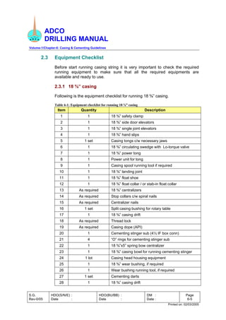
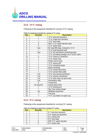
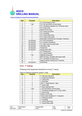
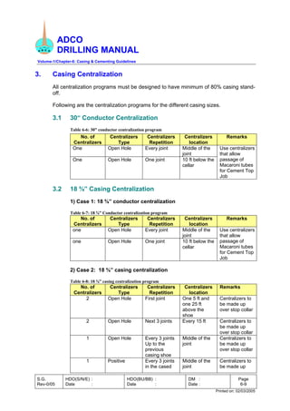
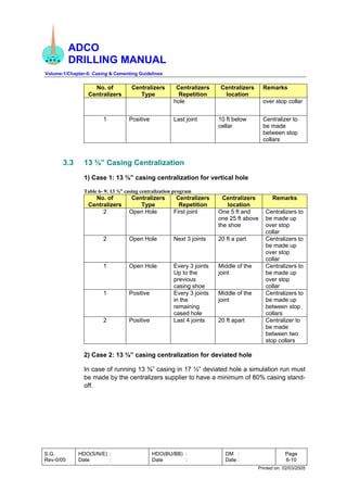
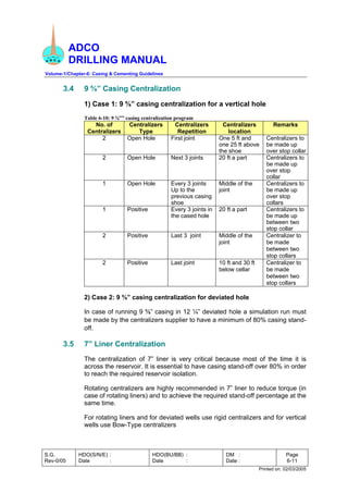
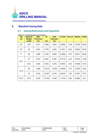
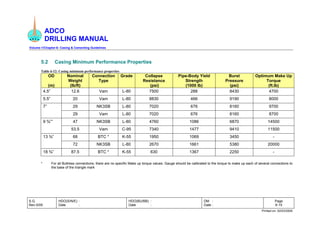
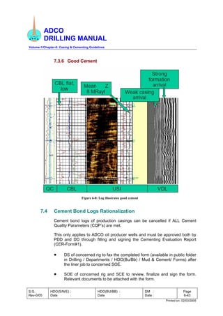
ADCO
DRILLING MANUAL
Volume-1/Chapter-6: Casing and Cementing Guidelines
CASING AND CEMENTING
Revision-0
March 2005
Chapter
6
ADCO
DRILLING MANUAL
Volume-1/Chapter-6: Casing and Cementing Guidelines
S.G.
Rev-0/05
HDO(S/N/E) :
Date :
HDO(BU/BB) :
Date :
DM :
Date :
Page
6-1
Printed on: 02/03/2005
Table of Contents
SECTION-1: CASING HANDLING, PREPARATION & RUNNING GUIDELINES .6-2
1. Introduction ..................................................................................................6-2
2. Casing Handling and Preparations Guidelines.............................................6-2
3. Casing Centralization ...................................................................................6-9
4. Running Casing..........................................................................................6-12
5. Standard Casing Data................................................................................6-14
SECTION-2: CEMENTING GUIDELINES.............................................................6-16
1. Introduction ................................................................................................6-16
2. Cementing General Guidelines ..................................................................6-20
3. 18 ⅝” Casing Cementing............................................................................6-25
4. 13 ⅜” Casing Cementation.........................................................................6-30
5. 9 ⅝” Casing Cementing..............................................................................6-33
6. 7” Liner Cementing.....................................................................................6-36
7. Evaluation of Primary Cement....................................................................6-38
ADCO
DRILLING MANUAL
Volume-1/Chapter-6: Casing & Cementing Guidelines
S.G.
Rev-0/05
HDO(S/N/E) :
Date :
HDO(BU/BB) :
Date :
DM :
Date :
Page
6-2
Printed on: 02/03/2005
SECTION 1
CASING HANDLING, PREPARATION & RUNNING GUIDELINES
1. Introduction
This Section provides the reader with the best practices for handling, preparing and
running casing strings. The material presented is a distillation of actual field
experience and information gathered from different places. In addition, this Section
contains technical data and information that is required for performing successful
casing operations.
All DD personnel involved in designing, planning and running casing are advised to
read this section and use it as a reference document.
2. Casing Handling and Preparations Guidelines
2.1 Handling
• Ensure that pipe racks are leveled and properly positioned to allow
transfer of casing from the racks to the catwalk.
• Ensure that thread protectors are placed on all connections before
loading or unloading casing.
• Avoid rough handling of casing which might damage in any fashion the
pipe body or connections. Dents in the casing body can reduce collapse
rating and lead to failure in service.
• Do not unload casing by dropping joints onto the racks. Maintain control
of the casing at all times by handling a small number of joints.
• Do not place hooks in the ends of casing. Joints should be slung from
spreaders, evenly spaced along the joints.
• When rolling casing on the racks, do not allow joints to strike each other.
• Always leave thread protectors in place when the casing is being
moved.
• Casing should be placed on level tumble racks or clean metal or
wooden surfaces, free of any debris.
ADCO
DRILLING MANUAL
Volume-1/Chapter-6: Casing & Cementing Guidelines
S.G.
Rev-0/05
HDO(S/N/E) :
Date :
HDO(BU/BB) :
Date :
DM :
Date :
Page
6-3
Printed on: 02/03/2005
2.2 Preparation and Inspection
2.2.1 On-Rack Preparations
• The rig crew should clean the connection threads (both pin and
box) and the protectors with a high pressure steam jet, followed
by an air blast to dry the item, to prevent thread and seal
corrosion
• Diesel or paraffin should not be used for thread cleaning since, if
not fully removed, a lack of lubricant adhesion to thread / seal
surfaces can result. Also, this type of medium does not
effectively clean the thread (it has a tendency to smear). It also
attracts foreign debris which can be encapsulated in the thread
roots, resulting in galling on make-up.
• Cleaning and drying should be of a quality that will allow all
features of the connection to be clearly visible
• After the threads and protectors are completely dry and clean
protectors should be re-installed. Failure to keep connections dry
before installing protectors can lead to thread / seal corrosion
due to entrapped water being held inside the pipe bore.
• If the casing is to be left for more than 10 days at the rig site,
corrosion protective grease should be applied to the
connections.
• Casing returned to Bab-13 has to be protected with storage
grease and casing protectors.
• All casing and accessory equipment should be visually inspected
before it is run in the hole. Where possible, the function of
accessory pieces should be confirmed before assembly.
• Damaged or undersized joints should be marked with red paint
and back loaded immediately. Record the reason for rejection on
the loading note returning them to drilling warehouse.
• The cleaning, inspection, and tallying operations are repeated as
each tier of casing is uncovered.
• If a mixed string is to be run (more than one grade and/or
weight), ensure that sufficient pipe of the required type is
available, and that it is laid out on the racks so that it will be
accessible when called for in the program.
• The casing tally will be recorded on the proper form and will
include all joints remaining on the rack. Tally numbers should be
planned so the shoe joint will be joint No.1.
ADCO
DRILLING MANUAL
Volume-1/Chapter-6: Casing & Cementing Guidelines
S.G.
Rev-0/05
HDO(S/N/E) :
Date :
HDO(BU/BB) :
Date :
DM :
Date :
Page
6-4
Printed on: 02/03/2005
• All measurements should be made with steel tape (with no
welds).
• With the thread protectors removed and the connections
cleaned, tally the casing and accessory pieces by measuring the
length from the face of the coupling to the point on the pin
connection where the coupling stops when the connection is
assembled power tight. The distance from the end of the pin
nose to this point is referred to as the make-up loss .Alternately,
the total length of the joint can be measured, and the make-up
loss subtracted from the overall length. Tallies should be made
to the nearest 0.01 ft.
2.2.2 Rig Floor Preparations
• The size and condition of all related handling equipment should
be checked thoroughly particularly, slips, elevators, back-up
tongs, and power tongs.
Note:
Slip and tong marks or gouges are injurious, and can result in
failure of the casing in service. Properly fitting and well
maintained equipment can greatly reduce the chance of
damaging the casing.
• Check that the blocks are centered over the rotary table. If not,
make the crew aware that the misalignment can result in
difficulty when stabbing and spinning up connections.
• Spider slips should be used for heavy casing strings or for critical
service casing. Again, the dies must be clean and sharp, and all
of the same size. Do not mix old or re-sharpened dies with new
dies in either the slips or the elevators.
• Check the rigging of the power tongs, making sure that the tong
back-up line is at right angles to the tongs, the tongs are level,
are free to move and are at the correct height above the floor.
• Check the size and rating of the power tongs. The nominal size
of the tongs should not be more than one size larger than the
pipe being run (i.e. do not use 13 3/8" tongs to run 7" casing)
and the tongs must be able to readily attain the maximum
expected torque.
• Ensure that the power tongs are equipped with an accurate and
reliable torque gauge either electronic or hydraulic.
• Check that the back-up tongs are level and do not interfere with
the suspension or operation of the power tongs.
ADCO
DRILLING MANUAL
Volume-1/Chapter-6: Casing & Cementing Guidelines
S.G.
Rev-0/05
HDO(S/N/E) :
Date :
HDO(BU/BB) :
Date :
DM :
Date :
Page
6-5
Printed on: 02/03/2005
2.3 Equipment Checklist
Before start running casing string it is very important to check the required
running equipment to make sure that all the required equipments are
available and ready to use.
2.3.1 18 ⅝” casing
Following is the equipment checklist for running 18 ⅝” casing.
Table 6-1: Equipment checklist for running 18 ⅝” casing
Item Quantity Description
1 1 18 ⅝” safety clamp
2 1 18 ⅝” side door elevators
3 1 18 ⅝” single joint elevators
4 1 18 ⅝” hand slips
5 1 set Casing tongs c/w necessary jaws
6 1 18 ⅝” circulating swedge with Lo-torque valve
7 1 18 ⅝” power tong
8 1 Power unit for tong
9 1 Casing spool running tool if required
10 1 18 ⅝” landing joint
11 1 18 ⅝” float shoe
12 1 18 ⅝” float collar / or stab-in float collar
13 As required 18 ⅝” centralizers
14 As required Stop collars c/w spiral nails
15 As required Centralizer nails
16 1 set Split casing bushing for rotary table
17 1 18 ⅝” casing drift
18 As required Thread lock
19 As required Casing dope (API)
20 1 Cementing stinger sub (4½ IF box conn)
21 4 “O” rings for cementing stinger sub
22 1 18 ⅝”x5” spring bow centralizer
23 1 18 ⅝” casing bowl for running cementing stinger
24 1 lot Casing head housing equipment
25 1 18 ⅝” wear bushing, if required
26 1 Wear bushing running tool, if required
27 1 set Cementing darts
28 1 18 ⅝” casing drift
ADCO
DRILLING MANUAL
Volume-1/Chapter-6: Casing & Cementing Guidelines
S.G.
Rev-0/05
HDO(S/N/E) :
Date :
HDO(BU/BB) :
Date :
DM :
Date :
Page
6-6
Printed on: 02/03/2005
2.3.2 13 ⅜” casing
Following is the equipment checklist for running 13 ⅜” casing.
Table 6-2: Equipment checklist for running 13 ⅜” casing
Item Quantity Description
1 1 13 ⅜” side door elevators
2 1 13 ⅜” single door elevators
3 1 13 ⅜” hand slips
4 2 350T 13 ⅜” spider elevator slips
5 2 13 ⅜” spider slips
6 1 set BJ Type BB tongs, dressed to 13 ⅜”
7 1 13 ⅜” plug dropping head
8 1 set 13 ⅜” top and bottom cementing plugs
9 1 13 ⅜” circulating swedge c/w 2” lo-torc valve
10 4 13 ⅜” Clamp on protectors
11 1 13 ⅜” power tong
12 1 Power unit for tong
13 1 13 ⅜” casing drift
14 1 13 ⅜” cementing plugs
15 2 Spare couplings
16 1 13 ⅜” cement float shoe
17 1 13 ⅜” cement float collar
18 1 lot 13 ⅜” bow spring centralizers
19 1 lot 13 ⅜” positive centralizers
20 1 lot 13 ⅜” stop rings c/w spiral nails
21 1 lot Centralizers nails
22 6 Thread lock
23 As required Casing dope (API)
24 1 13 ⅜” landing joint
25 1 Slip Type casing hanger
26 1 lot Wellhead equipment
27 1 Test plug
28 1 13 ⅜” cup tester c/w spare cup
2.3.3 9 ⅝” casing
Following is the equipment checklist for running 9 ⅝” casing.
Table 6-3: Equipment required for running 9 ⅝” casing
Item Quantity Description
1 1 9 ⅝” side door elevators
2 1 9 ⅝” single joint elevators
3 1 9 ⅝” casing drift
4 1 9 ⅝” hand slips
5 2 350T 9 ⅝” spider elevator
6 2 9 ⅝” spider slips
ADCO
DRILLING MANUAL
Volume-1/Chapter-6: Casing & Cementing Guidelines
S.G.
Rev-0/05
HDO(S/N/E) :
Date :
HDO(BU/BB) :
Date :
DM :
Date :
Page
6-7
Printed on: 02/03/2005
Item Quantity Description
7 1 9 ⅝” plug dropping head
8 1 set 9 ⅝” top and bottom cement plugs
9 1 9 ⅝” circulating swedge c/w 2” lo-torque valve
10 1 9 ⅝” power tong
11 1 Power unit for tong
12 2 9 ⅝” casing pup joints
13 2 9 ⅝” couplings
14 1 9 ⅝” cement float shoe
15 1 9 ⅝” cement float collar
16 2 Dual stage cementing set c/w plugs, if required
17 As required 9 ⅝” bow centralizers
18 As required 9 ⅝” positive centralizers
19 As required 9 ⅝” stop rings c/w spiral nails
20 As required Centralizer nails
21 As required Thread lock
22 As required Casing dope (API)
23 1 9 ⅝” landing joint
24 1 9 ⅝” casing hanger
25 1 lot Wellhead equipment
26 1 BOP test plug, complete with spare seals
27 1 9 ⅝” cup tester c/w spare cup
28 1 Stage cementer closing tool, if required
29 As required Auto fill tool
2.3.4 7” Casing
Following is the equipment checklist for running 7” casing.
Table 6-4: Equipment checklist for running 7” casing
Item Quantity Description
1 1 7” side door elevators
2 1 7” single joint elevators
3 1 7” casing drift
4 1 7” hand slips
5 2 350T 7” single elevator / slips
6 2 7” spider slips
7 1 7” plug dropping head
8 1 set 7” top and bottom cement plugs
9 1 7” circulating swedge c/w 2” Lo-torc valve
10 1 7” power tong
11 1 Power unit for tong
12 1 Travel cutter dressed to 7”, if required
13 2 7” casing pup joints
14 2 7” couplings
15 1 7” cement float shoe
16 1 7” cement float collar
ADCO
DRILLING MANUAL
Volume-1/Chapter-6: Casing & Cementing Guidelines
S.G.
Rev-0/05
HDO(S/N/E) :
Date :
HDO(BU/BB) :
Date :
DM :
Date :
Page
6-8
Printed on: 02/03/2005
Item Quantity Description
17 As required 7” open hole centralizers
18 As required 7” positive centralizers
19 As required 7” stop rings c/w spiral nails
20 As required Centralizer nails
21 As required Thread lock
22 As required Casing dope (API)
23 1 7” landing joint
24 1 7” casing hanger
25 1 lot Wellhead equipment
26 1 Test plug
27 1 7” cup tester c/w spare cup
28 1 Cement head
29 1 set Cementing plugs
30 As required Liner Top Packer
2.3.5 7” Liner
Following is the equipment checklist for running 7” liner.
Table 6-5: Equipment checklist for running 7” liner
Item Quantity Description
1 2 7” side door elevators
2 2 7” single joint elevators c/w swivel sling
3 2 7” rotary hand slips
4 2 Power tong dressed for 7” casing
5 2 Hydraulic power unit for above
6 2 Torque – turn units (if required)
7 6 Spare casing collars
8 1 7” casing spear c/w grapple / pack-off and stop
ring. (Specify weight)
9 As required 7” centralizers(as per simulation run)
10 As required 7” stop collars
11 1 7” casing drift (Teflon drift for CRA casing)
12 As required Casing dope (API)
13 As required Thread lock
14 1 set 7” casing liner hanger
15 1 Cement head with heavy duty swivel and dart
marker
16 1 7” circulating swedge c/w 2” Lo-torc valve
17 1 set Setting and cementing equipment (ball, plug…)
18 1 Cementing Kelly
19 1 7” casing drift
ADCO
DRILLING MANUAL
Volume-1/Chapter-6: Casing & Cementing Guidelines
S.G.
Rev-0/05
HDO(S/N/E) :
Date :
HDO(BU/BB) :
Date :
DM :
Date :
Page
6-9
Printed on: 02/03/2005
3. Casing Centralization
All centralization programs must be designed to have minimum of 80% casing stand-
off.
Following are the centralization programs for the different casing sizes.
3.1 30“ Conductor Centralization
Table 6-6: 30” conductor centralization program
No. of
Centralizers
Centralizers
Type
Centralizers
Repetition
Centralizers
location
Remarks
One Open Hole Every joint Middle of the
joint
One Open Hole One joint 10 ft below the
cellar
Use centralizers
that allow
passage of
Macaroni tubes
for Cement Top
Job
3.2 18 ⅝” Casing Centralization
1) Case 1: 18 ⅝” conductor centralization
Table 6-7: 18 ⅝” Conductor centralization program
No. of
Centralizers
Centralizers
Type
Centralizers
Repetition
Centralizers
location
Remarks
one Open Hole Every joint Middle of the
joint
one Open Hole One joint 10 ft below the
cellar
Use centralizers
that allow
passage of
Macaroni tubes
for Cement Top
Job
2) Case 2: 18 ⅝” casing centralization
Table 6-8: 18 ⅝” casing centralization program
No. of
Centralizers
Centralizers
Type
Centralizers
Repetition
Centralizers
location
Remarks
2 Open Hole First joint One 5 ft and
one 25 ft
above the
shoe
Centralizers to
be made up
over stop collar
2 Open Hole Next 3 joints Every 15 ft Centralizers to
be made up
over stop collar
1 Open Hole Every 3 joints
Up to the
previous
casing shoe
Middle of the
joint
Centralizers to
be made up
over stop collar
1 Positive Every 3 joints
in the cased
Middle of the
joint
Centralizers to
be made up
ADCO
DRILLING MANUAL
Volume-1/Chapter-6: Casing & Cementing Guidelines
S.G.
Rev-0/05
HDO(S/N/E) :
Date :
HDO(BU/BB) :
Date :
DM :
Date :
Page
6-10
Printed on: 02/03/2005
No. of
Centralizers
Centralizers
Type
Centralizers
Repetition
Centralizers
location
Remarks
hole over stop collar
1 Positive Last joint 10 ft below
cellar
Centralizer to
be made
between stop
collars
3.3 13 ⅜” Casing Centralization
1) Case 1: 13 ⅜” casing centralization for vertical hole
Table 6- 9: 13 ⅜” casing centralization program
No. of
Centralizers
Centralizers
Type
Centralizers
Repetition
Centralizers
location
Remarks
2 Open Hole First joint One 5 ft and
one 25 ft above
the shoe
Centralizers to
be made up
over stop
collar
2 Open Hole Next 3 joints 20 ft a part Centralizers to
be made up
over stop
collar
1 Open Hole Every 3 joints
Up to the
previous
casing shoe
Middle of the
joint
Centralizers to
be made up
over stop
collar
1 Positive Every 3 joints
in the
remaining
cased hole
Middle of the
joint
Centralizers to
be made up
between stop
collars
2 Positive Last 4 joints 20 ft apart Centralizer to
be made
between two
stop collars
2) Case 2: 13 ⅜” casing centralization for deviated hole
In case of running 13 ⅜” casing in 17 ½” deviated hole a simulation run must
be made by the centralizers supplier to have a minimum of 80% casing stand-
off.
ADCO
DRILLING MANUAL
Volume-1/Chapter-6: Casing & Cementing Guidelines
S.G.
Rev-0/05
HDO(S/N/E) :
Date :
HDO(BU/BB) :
Date :
DM :
Date :
Page
6-11
Printed on: 02/03/2005
3.4 9 ⅝” Casing Centralization
1) Case 1: 9 ⅝” casing centralization for a vertical hole
Table 6-10: 9 ⅝”” casing centralization program
No. of
Centralizers
Centralizers
Type
Centralizers
Repetition
Centralizers
location
Remarks
2 Open Hole First joint One 5 ft and
one 25 ft above
the shoe
Centralizers to
be made up
over stop collar
2 Open Hole Next 3 joints 20 ft a part Centralizers to
be made up
over stop
collar
1 Open Hole Every 3 joints
Up to the
previous casing
shoe
Middle of the
joint
Centralizers to
be made up
over stop
collars
1 Positive Every 3 joints in
the cased hole
20 ft a part Centralizers to
be made up
between two
stop collar
2 Positive Last 3 joint Middle of the
joint
Centralizer to
be made
between two
stop collars
2 Positive Last joint 10 ft and 30 ft
below cellar
Centralizer to
be made
between two
stop collars
2) Case 2: 9 ⅝” casing centralization for deviated hole
In case of running 9 ⅝” casing in 12 ¼” deviated hole a simulation run must
be made by the centralizers supplier to have a minimum of 80% casing stand-
off.
3.5 7” Liner Centralization
The centralization of 7” liner is very critical because most of the time it is
across the reservoir. It is essential to have casing stand-off over 80% in order
to reach the required reservoir isolation.
Rotating centralizers are highly recommended in 7” liner to reduce torque (in
case of rotating liners) and to achieve the required stand-off percentage at the
same time.
For rotating liners and for deviated wells use rigid centralizers and for vertical
wells use Bow-Type centralizers
ADCO
DRILLING MANUAL
Volume-1/Chapter-6: Casing & Cementing Guidelines
S.G.
Rev-0/05
HDO(S/N/E) :
Date :
HDO(BU/BB) :
Date :
DM :
Date :
Page
6-12
Printed on: 02/03/2005
Also it is essential to perform simulation for the centralization program using
the actual hole survey to determine the number and the locations of
centralizers.
4. Running Casing
4.1 General Guidelines
• Remove pin and box protectors from casing and accessory pieces, and
thoroughly clean the connections, removing all previously applied thread
or storage compound.
• When moving pipe from the racks to the catwalk, ensure that joints are
not dropped or allowed to hit against other casing or rig equipment.
Casing should be pulled up to the V-door with a choker, and then single
joint elevators used to pull the casing joint into the derrick. Thread
protectors must be in place on both pin and box connections any time
the pipe or accessories are moved.
• Once the casing has been pulled into the derrick, the pin end thread
protector can be removed, thread compound applied and the joint
stabbed.
• In stabbing the joint, use stabbing guides, lower the casing slowly to
avoid connection damage, and ensure that the connection is aligned
before starting rotation. For large casing, and if there is any
misalignment of the blocks over the rotary, a man on the stabbing board
can be of great assistance.
• If the casing does not stab correctly or jams, the pin should be picked up
from the box, both connections cleaned, inspected, and repaired
(remove any filings or wickers), thread compound re-applied, and the
connection re-stabbed.
• Once the joint is stabbed, make-up can proceed, with the connection
being spun up slowly initially, ensuring that the connection is not cross-
threaded or jammed.
• API Round and Buttress connections are assembled to position; the
assembly torque values provided are representative of the torque range
required to attain the power-tight position based on nominal conditions,
and must be used only as a guide. Torque must relate to the make-up
position, and as a result, the torques used in the field for a given
connection can vary from those listed.
• Casing must be lowered carefully, first to avoid shock loads to the
casing string, but also to prevent pressure surges which may damage
downhole formations. The slips must not be set until all downward
ADCO
DRILLING MANUAL
Volume-1/Chapter-6: Casing & Cementing Guidelines
S.G.
Rev-0/05
HDO(S/N/E) :
Date :
HDO(BU/BB) :
Date :
DM :
Date :
Page
6-13
Printed on: 02/03/2005
motion of the casing string has stopped. Great care should be exercised
to ensure that the string does not spud the bottom of the hole the
compressive loads can cause the string to buckle and/or connections to
loosen with the subsequent risk of failure in service.
• Note that often there is a predetermined running order for casing and
related accessories due to design criteria or downhole conditions. It is
vital that this order be followed, and in the event that a specific joint of
casing cannot be identified with respect to its weight or grade, the joint
should not be run.
ADCO
DRILLING MANUAL
Volume-1/Chapter-6: Casing & Cementing Guidelines
S.G.
Rev-0/05
HDO(S/N/E) :
Date :
HDO(BU/BB) :
Date :
DM :
Date :
Page
6-14
Printed on: 02/03/2005
5. Standard Casing Data
5.1 Casing Dimensions and Capacities
Table 6-11: Casing dimension and capacities
OD
(in)
Nominal
Weight
(Lb/ft)
Wall
Thickness
(in)
ID
(in)
Drift
Diameter
(in)
Cu.ft/ft Ft/cu.ft Bbls/ft Ft/bbl
4.5” 12.6 0.271 3.958 3.833 0.0855 11.69 0.0152 65.65
5.5” 20 0.361 4.778 4.653 0.1241 8.06 0.0222 45.04
7” 29 0.408 6.184 6.059 0.2086 4.79 0.0371 26.95
47 0.472 8.681 8.525 0.4110 2.43 0.0732 13.66
9 ⅝””
53.5 0.545 8.535 8.379 0.3973 2.52 0.0708 14.12
68 0.480 12.415 12.259 0.8406 1.19 0.1497 6.68
13 ⅜”
72 0.514 12.347 12.191 0.8315 1.20 0.1481 6.75
18 ⅝” 87.5 0.435 17.755 17.567 1.7193 0.58 0.3062 3.27
ADCO
DRILLING MANUAL
Volume-1/Chapter-6: Casing & Cementing Guidelines
S.G.
Rev-0/05
HDO(S/N/E) :
Date :
HDO(BU/BB) :
Date :
DM :
Date :
Page
6-15
Printed on: 02/03/2005
5.2 Casing Minimum Performance Properties
Table 6-12: Casing minimum performance properties
OD
(m)
Nominal
Weight
(lb/ft)
Connection
Type
Grade Collapse
Resistance
(psi)
Pipe-Body Yield
Strength
(1000 lb)
Burst
Pressure
(psi)
Optimum Make Up
Torque
(ft.lb)
4.5” 12.6 Vam L-80 7500 288 8430 4700
5.5” 20 Vam L-80 8830 466 9190 8000
29 NK3SB L-80 7020 676 8160 9700
7”
29 Vam L-80 7020 676 8160 8700
47 NK3SB L-80 4760 1086 6870 14500
9 ⅝””
53.5 Vam C-95 7340 1477 9410 11500
68 BTC * K-55 1950 1069 3450 -
13 ⅜”
72 NK3SB L-80 2670 1661 5380 20000
18 ⅝” 87.5 BTC * K-55 630 1367 2250 -
* For all Buttress connections, there are no specific Make up torque values. Gauge should be calibrated to the torque to make up each of several connections to
the base of the triangle mark
ADCO
DRILLING MANUAL
Volume-1/Chapter-6: Casing & Cementing Guidelines
S.G.
Rev-0/05
HDO(S/N/E) :
Date :
HDO(BU/BB) :
Date :
DM :
Date :
Page
6-16
Printed on: 02/03/2005
SECTION 2
CEMENTING GUIDELINES
1. Introduction
1.1 Cementing General
Good planning, programming and preparation plays an extremely important
role in cementing operations, especially as it necessitates the gathering of a
quantity of specialized material and equipment, and a number of skilled
personnel at a single location. A shortfall in the quantity or quality of material
or equipment, or the non availability of a person with the requisite skills could
lead to an expensive suspension of operations. This Section provides reader
of the best practices to plan, design and implement a successful cement
operation.
1.2 Cementing Responsibilities
1.2.1 Cement Group
Cement Group provides technical, administrative and logistic support
to the rig and thereby enables the safe delivery of the correct quantity
of product and personnel at optimum cost.
Cement Group is responsible of:
• All aspects of cementing servicing from the design stage to the
execution.
• Development of cementing policy and procedures in close
consultation with the Operations Teams.
• Cementing technical auditing and trouble shooting.
• New cementing materials
1.2.2 Drilling Contractor
The following minimum checks and procedures are to be performed
by the drilling contractor
• Air up all tanks the day before the cement job, check for leaks.
Carry out repairs immediately.
• Pressure test and physically check all supply lines and valves
from the rig to the cement unit.
ADCO
DRILLING MANUAL
Volume-1/Chapter-6: Casing & Cementing Guidelines
S.G.
Rev-0/05
HDO(S/N/E) :
Date :
HDO(BU/BB) :
Date :
DM :
Date :
Page
6-17
Printed on: 02/03/2005
• Prepare displacement tanks; make sure the mud volumes are
correct.
• Prepare separate tanks for return with accurate measurements.
• Make sure the correct displacement efficiencies are correctly
measured.
• Make sure the pump displacement lines are blocked up
correctly.
• Report to the Drilling Supervisor when all the above inspections
have been completed.
1.2.3 Cement Operator
The cement operator’s duties are:
• Maintain and operate the cementing installation and all
associated equipment on the rig to the highest standards of
reliability, and ensure that the unit has valid certification,
including certification for any densitometer with a radio-active
source.
• Record stock levels of cement and additives and maintain quality
control. Maintain adequate spare parts and consumables to
support the operations. Maintain a log book of all materials used
and delivered.
• Carry out individual cement calculations and verify calculations
performed by the wellsite drilling engineer and Drilling
Supervisor.
• Perform the cement job as per the programme specified by the
company, including the use of liquid additive dispensing units
and data recording devices.
• Obtain representative samples of cements and additives and
forward these in good time for laboratory testing, properly
packaged.
• Check the cement unit and equipment and ensure the following:
o Unit and lines are pressure tested to minimum 1000 psi
above casing test pressure using a chart recorder.
o Unit displacement tank barrel scale is accurate.
o Displacement tank valves do not leak, and are easily
operable.
o Low pressure mixing system is flushed through.
ADCO
DRILLING MANUAL
Volume-1/Chapter-6: Casing & Cementing Guidelines
S.G.
Rev-0/05
HDO(S/N/E) :
Date :
HDO(BU/BB) :
Date :
DM :
Date :
Page
6-18
Printed on: 02/03/2005
o Packings on mix pumps are operable.
o Pressure on mix pumps is more than adequate for mixing.
o Unit’s computer is in good working conditions.
o Jets in mixer are correct.
o Bypass valve on mix manifold is working.
o Bypass on mixer is open (manually).
o Engine oil and water are at correct levels.
o Oil in pumps is at correct levels.
o Hoses are serviceable.
o Hopper is serviceable.
o Cement head, i.e. valves, threads, indicators and plug
locator pins are all operable.
o Volume of additives is sufficient to provide 100% of job
requirements.
o Water supply rate to displacement tanks or batch tank
exceeds maximum estimated requirement.
o Batch mixer and Air compressor is operating correctly.
o Each cement silos is marked with the type of cement
inside.
o Dust arrestors are installed.
1.2.4 Field Cement Engineer (if present)
• Ensure cement, additive and mixwater samples are sent in
correctly marked and packaged.
• Collect samples during the cement job.
• Confirm stock levels of cement and additives.
• Collate downhole temperature data as a check on cement slurry
design. Compare to test temperature.
• Witness and check quality control of caliper logs (if present).
• Compute slurry volumes from caliper (if present).
• Prepare individual calculations for the cement job, Compare
results with the separate calculations carried out by the Drilling
Supervisor and cementer.
• Verify and monitor mixwater volumes, displacement volumes
and pressure during the cement job.
ADCO
DRILLING MANUAL
Volume-1/Chapter-6: Casing & Cementing Guidelines
S.G.
Rev-0/05
HDO(S/N/E) :
Date :
HDO(BU/BB) :
Date :
DM :
Date :
Page
6-19
Printed on: 02/03/2005
• Supervise preparation of spacers, cement and additives. Ensure
cement is fluffed as per recommended procedure.
• Prepare all cementation reports.
1.2.5 Drilling Supervisor
• Inform the RM and Driller of:
o The volume of each type of mix water to be used for both
lead and tail cement jobs.
o From which mud pit each type of mix water will be drawn.
o The expected gain, per barrel of mix water blended with
cement, for both lead and tail slurries.
o The expected total volume of returns during the cement job
and the expected overall increase in pit volume.
• Supervise the FCE, if present, cementers and drilling contractor
in the performance of their duties.
• Prepare individual calculations for the cement job.
• Check the mud pumps efficiency.
• Approve all reports, worksheets and job tickets.
• Co-ordinate the planning and execution of the cement job.
Ensure that all relevant personnel are issued with a detailed
programme of the cement job, highlighting individual
responsibilities. The detailed programme must include volumes,
pressures and pump rates for the cementing and displacing
operations. Contingency plans must also be drawn up for any
equipment failure, etc. Procedures must be written to cover
alternative mix water supply, rig pump failure, alternative
mixwater and displacement valve measurement and procedures
if predicted pressures are exceeded or return volumes
insufficient to maintain displacement with mud.
1.2.6 Mud Engineer
• Check the mix-water for contamination and salinity.
• Ensure that a sufficient volume of mud is available on the
surface prior to commencement of the cementation.
• Monitor pit volumes throughout the cementation.
• Calibrate mud tanks and check the mud and cement returns
ADCO
DRILLING MANUAL
Volume-1/Chapter-6: Casing & Cementing Guidelines
S.G.
Rev-0/05
HDO(S/N/E) :
Date :
HDO(BU/BB) :
Date :
DM :
Date :
Page
6-20
Printed on: 02/03/2005
1.2.7 Senior Cement Engineer
The Senior Cement Engineer will have the following responsibilities:
• Discuss and agree with the operation teams on the required
cement slurries and volumes.
• Request, review and agree on the cement recipe received from
ADCO lab.
• Prepare and review the cement job program, discuss any
changes needed with the operation team.
• Report to Team Leader (Mud and Cement)
• Ensure that a comprehensive administrative recording and filing
system is maintained to assist the Drilling Engineers as a part of
lesson learnt
• Be responsible for the Cement Engineers and ensure full
utilization all this within the boundaries of HSE.
• Ensure applications and recording of Cement Quality
Parameters (CQPs) evaluation.
2. Cementing General Guidelines
The operation checklist is to be used and referred to at all times when planning and
preparing for cementing operations.
2.1 Prior to Cement Job
• The following procedures must be strictly followed for cement
formulation
o ADCO laboratory is sending first a PRELIMINARY recipe (typical
formulation for the type of operation & conditions) by fax to the rig
for ordering purposes (cement, blends & additives).
o Actual samples of cement &/or blends delivered to the rigs are
tested by the service company & ADCO laboratory.
o Service Company laboratory results will be communicated to
ADCO laboratory for review and must NOT be sent to the rig
directly.
o ADCO laboratory is sending the final (revised) recipe (based on
actual cement samples for the job) by fax to the rig approved by
SCE.
ADCO
DRILLING MANUAL
Volume-1/Chapter-6: Casing & Cementing Guidelines
S.G.
Rev-0/05
HDO(S/N/E) :
Date :
HDO(BU/BB) :
Date :
DM :
Date :
Page
6-21
Printed on: 02/03/2005
• Ensure that the FINAL ADCO laboratory WRITTEN recipe approved by
C&MDTL is implemented during the cementing job. Verbal
communication of formulations must be avoided.
• Ensure the following samples are sent to ADCO lab prior to cement job
for lab testing:
Cement from each silo 10 kg
Mix water 1 gal
Liquid additives 500 ml
• Ensure thickening time is adequate for anticipated duration of the job.
• Ensure calipers (if presented) have been calibrated inside previous
casing shoe. Compare different calipers with each other. Check for any
off scale washouts on the caliper.
• Calculate any reduction in hydrostatic head due to cement spacers.
Check overbalance. Assume gauge hole. Ensure overbalance is
maintained through all stages of the job.
• Beware of gel strength development in slurries particularly at elevated
temperatures in the range of 180-250 deg F. Be particularly concerned
to minimize unnecessary shutdowns during mixing and pumping.
• Check maximum expected ECD against shoe strength.
• Ensure sufficient chemicals on location for double the estimated
quantity, providing 100% contingency.
• Ensure that a pressurized mud balance for determining densities of
critical slurries is available. Many Types of slurry will entrain air which
will cause them to weight much less than downhole density in a
standard mud balance.
• Ensure that all necessary equipment is on rig and checked out. In
particular, when surface release cement plugs are to be used, check the
condition of the surface cement head.
• Ensure that the cement unit and all lines to the rig floor are flushed
through and pressure tested as specified several hours before
cementing is to take place.
• Check the mix water transfer line for leaks.
• Check chloride content of the mix water.
ADCO
DRILLING MANUAL
Volume-1/Chapter-6: Casing & Cementing Guidelines
S.G.
Rev-0/05
HDO(S/N/E) :
Date :
HDO(BU/BB) :
Date :
DM :
Date :
Page
6-22
Printed on: 02/03/2005
• Ensure mud pumps are hooked up correctly to the displacement
position, all valves and gates checked for leak.
• Both the Driller and the Mud Engineer are to prepare pit and flowlines
for the expected total returns. (The system must be prepared to accept
the total volume returned equal to the volume of slurry and spacers are
to be pumped).
• The Driller and the Mud Engineer are to record the volumes in each
individual pit and the total volume in the pits.
• After the mud pits have been prepared, no mud is to be transferred or
dumped without prior permission from the Drilling Supervisor.
• Recheck cementing program for the risk of casing Collapse, Burst and
Floatation.
2.2 During the Cement Job
• Ensure the following samples are taken at regular intervals during the
cement jobs in case of problems:
Cement from Surge Tank 10 kg
Actual Mix Water with Additives 1 gal
Drill Water 1 gal
Individual Liquid Additives 500 ml
Slurry Samples 5-10 cups
Check density of the liquid additives prior to use.
Notes:
o Mix water samples should be collected at the beginning, middle
and end of the lead and tail slurry.
o Retain the slurry samples for observation.
• Maintain plot of displacement vs. top of cement and also position of top
plug. Compare theoretical and actual pressures.
• The Drilling Supervisor / Field Cement Engineer to inform both the Mud
Engineer and the Driller periodically of the amounts of mix water used.
• Ensure cement operator changes displacement tanks correctly to
minimize error in slurry or displacement volumes.
• Avoid the possibility of pumping diluted cement or even water into
casing before the top plug is released.
ADCO
DRILLING MANUAL
Volume-1/Chapter-6: Casing & Cementing Guidelines
S.G.
Rev-0/05
HDO(S/N/E) :
Date :
HDO(BU/BB) :
Date :
DM :
Date :
Page
6-23
Printed on: 02/03/2005
• Using spacers and flushes is very effective in enhancing the cement job
because the spacer improve removal of gelled mud, which allowing a
better cement bond.
In order to obtain the maximum benefits of the spacers, consider the
following.
o Bump the spacer fluid at an optimized rate.
o Provide a contact time and volume of spacer that will remove the
greatest possible amount of mud cake, as guideline use a volume
of spacer which occupies 500 ft in annulus or 10 min. contact time.
• Moving the pipe before and during the cement job improve the
displacement efficiency, Aids in cutting removal and break mud gel
strength. If the pipe poorly centralized, the movement can create flow
path through the casing and allowing the slurry to circulate completely
around the casing.
In some cases pipe movement is not recommended specially when
losses is experienced and the surge produced by the pipe movement
will increase the losses
• Displacement rate is very effective in cement job quality, the best result
could be obtained when the spacer and/or cement is pumped at
maximum allowable rate. The displacement rates should be limited to
the maximum allowable ECD or as per the job simulation.
• Conditioning mud prior to the cement job helps in improving the cement
job quality. During conditioning mud we need to
o Break mud gel
o Lower yield Point
o Keep solids<10%
o Circulate>95% of the total hole capacity (minimum of 2 hole
cycles)
• Physically ascertain the amount of fluid pumped from the pits, and
check that the pits are dropping by the requisite amount during the
displacement (don’t rely on pump stroke counters).
• If more than one pit is required equalize across two pits and pump the
displacement, if that is not possible then displace a volume from one pit,
stop the pumps, line up to the second pit and complete the
displacement.
• Displace the cement with mud. Determine the displacement volume,
pump strokes and pumping time at which the displacement rate should
be reduced prior to bumping the plugs. Displace cement at maximum
rate allowable from pressure consideration unless advised otherwise.
ADCO
DRILLING MANUAL
Volume-1/Chapter-6: Casing & Cementing Guidelines
S.G.
Rev-0/05
HDO(S/N/E) :
Date :
HDO(BU/BB) :
Date :
DM :
Date :
Page
6-24
Printed on: 02/03/2005
• The active pit gain is to be monitored continuously during cementing.
Expect additional return volumes during mixing and reduced return rates
during initial displacing. Ensure any losses are noted.
• Displace from the cementing unit in the following cases:
o When no rig pumps available. Control volume by measuring from
mud tanks as well as cement unit displacement tanks.
o When placing cement plugs or cementing through drill pipe.
o Liner cementations.
• If rig pump is used, have cementer’s pump unit ready to take over to
pump the plugs in case the pressure becomes excessive. Record all
mixing, displacing, pumping, etc on pressure chart.
• The Mud Engineer / Driller are to record the total volume in the pits and
inform ADCO Supervisor / Drilling Engineer of the volume gained (or
lost) during the entire cement job.
• After bumping top plug, release pressure, measure returns and check
for backflow.
• If there is backflow, bump back the amount of backflow only and re-
pressure the casing. If there is still backflow, hold pressure and wait until
the cement is hard before repeating the test.
• Pressure test casing immediately after bumping plug (15 min. API).
• Every single job with the cement unit (regardless of type or importance)
MUST be recorded with the unit computer (pump rate, pumping
pressure, cumulative volume, ... etc) and the relevant chart (properly
documented) provided to the DS with the job log and with the contractor
invoice.
ADCO
DRILLING MANUAL
Volume-1/Chapter-6: Casing & Cementing Guidelines
S.G.
Rev-0/05
HDO(S/N/E) :
Date :
HDO(BU/BB) :
Date :
DM :
Date :
Page
6-25
Printed on: 02/03/2005
3. 18 ⅝” Casing Cementing
The 18 ⅝” casing should be cemented using either Stinger Technique of Plug
and bump technique.
3.1 18 ⅝” Casing Cementing Job Calculations
3.1.1 Stinger Technique
Assumptions:
D = Annulus Capacity between 18 ⅝” casing and 26” hole or 22” hole
(cu.ft/ft)
E = Slurry Yield (cu.ft/sk)
F = Slurry Mix Water (gal/sk)
G = Drill Pipe Capacity (bbl/ft)
M = Annulus capacity between 18 ⅝” casing and 30” conductor (cu.ft/ft)
Figure 6-1: Cementing 18 ⅝” Casing with cementing stinger
18 ⅝” Casing
Cement
G.L.
Cement Slurry
RT
2” Valve
DP with stinger
A
B
C
30” Conductor
K
26” or 22” hole
ADCO
DRILLING MANUAL
Volume-1/Chapter-6: Casing & Cementing Guidelines
S.G.
Rev-0/05
HDO(S/N/E) :
Date :
HDO(BU/BB) :
Date :
DM :
Date :
Page
6-26
Printed on: 02/03/2005
Calculation Sheet for 18 ⅝” Casing Cementing Job (Stinger Technique)
Table 6-13: 18 ⅝” casing cementing calculations (Stinger Technique)
Elevation / Depth
Data (See Figure 6-1)
K = ft
A = ft
B = ft Slurry Volume (H) Number of Sacks ( I ) Slurry Mix Water (J)
C = ft (cu.ft) (sk) (gal)
IT = HT / ET JT = IT x FT
Tail Slurry
95 bbls to be used
HT = A x D x Open Hole Excess = ………..cu.ft
= ……………sk
=…………gal
IL = HL / EL JL = IL x FL
Lead Slurry
HL =( B x D x Open Hole Excess) + (K x M x Cased
Hole Excess) = ………..cu.ft = ……………sk =…………gal
Displacement = G x (A+B+C+K) = ………..bbl
Note:
- Open Hole Excess = 50%
- Cased Hole Excess = 10%
ADCO
DRILLING MANUAL
Volume-1/Chapter-6: Casing & Cementing Guidelines
S.G.
Rev-0/05
HDO(S/N/E) :
Date :
HDO(BU/BB) :
Date :
DM :
Date :
Page
6-27
Printed on: 02/03/2005
3.1.2 Plug and Bump Technique
Assumptions:
F = Annulus Capacity between 18 ⅝” casing and 26” or 22” hole
(cu.ft/ft)
G = Annulus Capacity between 18 ⅝” casing and 30” conductor
(cu.ft/ft)
H = 18 ⅝” casing capacity (bbl/ft)
I = Slurry Yield (cu.ft/sk)
J = Slurry Mix Water (gal/sk)
Figure 6-2: Cementing 18 ⅝” Casing (Plug and Bump Technique)
18 ⅝” Casing
Cement
RT
Cement Slurry
2” Valve
A
B
C
D
E
G.L.
30” Conductor
26” or 22” hole
ADCO
DRILLING MANUAL
Volume-1/Chapter-6: Casing & Cementing Guidelines
S.G.
Rev-0/05
HDO(S/N/E) :
Date :
HDO(BU/BB) :
Date :
DM :
Date :
Page
6-28
Printed on: 02/03/2005
Calculation Sheet for 18 ⅝” Casing Cementing Job (plug and Bump Technique)
Table 6-14: 18 ⅝” casing cementing calculations (Bump and Plug technique)
Elevation/Depth
Data (See Figure 6-2)
A = ft
B = ft
C = ft
D = ft
Slurry Volume (K) Number of Sacks
(L)
Slurry Mix Water (M)
G = ft (cu.ft) (sk) (gal)
LT = KT / IT MT = JT x LT
Tail Slurry KT= (A x H)+{(B x F) x Open Hole Excess} = …….cu.ft =………..sk =………..gal
LL = KL / IL ML = JL x LL
Lead Slurry KL=(C x F x Open Hole Excess)+{D x G x Cased Hole Excess}=… …cu.ft =………..sxs =………..gal
Displacement = H x (B+C+D+E-A) =……….bbl
Note:
- Open Hole Excess = 50%
- Cased Hole Excess = 10%
ADCO
DRILLING MANUAL
Volume-1/Chapter-6: Casing & Cementing Guidelines
S.G.
Rev-0/05
HDO(S/N/E) :
Date :
HDO(BU/BB) :
Date :
DM :
Date :
Page
6-29
Printed on: 02/03/2005
3.2 18 ⅝” Casing Cement Slurry
Table 6-15: 18 ⅝” casing cement slurry composition and properties
Lead Tail
Casing Setting
Depth Range
(ft) Slurry
Weight
( pcf)
Thickening
Time (Hrs)
Compressive
Strength
Slurry
Weight
(pcf)
Thickening
Time
(Hrs)
Compressive
Strength
100-500 "G" 118 >= 4
>= 2700 psi @105
Deg F
- - - -
500-2800
Light
Weight
86 >=6
>= 750 psi @ 105
Deg F
"G" 118 >= 4
>= 2700 psi @110
Deg F
Note:
- Excess on open hole = 50%
- Excess on cased hole= 10%
For detailed cementing procedure refer to the relevant Section in Chapter-2 “Drilling Operations Guidelines” of this Volume.
ADCO
DRILLING MANUAL
Volume-1/Chapter-6: Casing & Cementing Guidelines
S.G.
Rev-0/05
HDO(S/N/E) :
Date :
HDO(BU/BB) :
Date :
DM :
Date :
Page
6-30
Printed on: 02/03/2005
4. 13 ⅜” Casing Cementation
4.1 13 ⅜” Casing Cementing Job Calculations
Assumptions:
F = Annulus Capacity between 13 ⅜” casing and 17 ½” or 16” hole (cu.ft/ft)
G = Annulus Capacity between 13 ⅜” casing and 18 ⅝” casing (cu.ft/ft)
H = 13 ⅜” casing capacity (bbl/ft)
I = Slurry Yield (cu.ft/sk)
J = Slurry Mix Water (gal/sk)
Figure 6-3: Cementing 13 ⅜” Casing
18 ⅝” Casing
Cement
Cement Slurry
RT
A
B
C
D
E
13 ⅜” Casing
G.L.
17 ½” or 16” Hole
ADCO
DRILLING MANUAL
Volume-1/Chapter-6: Casing & Cementing Guidelines
S.G.
Rev-0/05
HDO(S/N/E) :
Date :
HDO(BU/BB) :
Date :
DM :
Date :
Page
6-31
Printed on: 02/03/2005
Calculation Sheet for 13 ⅜” Casing Cementing Job
Table 6-16: 13 ⅜” casing cementing calculations
Elevation/Depth
Data(See Figure 6-3)
A = ft
B = ft
C = ft
D = ft Slurry Volume (K)
Number of Sacks
(L)
Slurry Mix Water
(M)
E = ft (cu.ft) (sk) (gal)
LT = KT / IT MT = JT x LT
Tail Slurry KT= (A x H)+{(B x F) x Open Hole Excess} = …….cu.ft =………..sk =………..gal
LL = KL / IL ML = JL x LL
Lead Slurry KL=(D x G x Cased Hole Excess)+{(C x F) x Open Hole Excess} = … …cu.ft =………..sk =………..gal
Displacement = H x (B + C + D + E - A) =……….bbl
Note:
- Excess on open hole volumes = 50 - 80% based on the amount of losses during drilling 17 ½” section.
- Excess on cased hole volumes = 10%
ADCO
DRILLING MANUAL
Volume-1/Chapter-6: Casing & Cementing Guidelines
S.G.
Rev-0/05
HDO(S/N/E) :
Date :
HDO(BU/BB) :
Date :
DM :
Date :
Page
6-32
Printed on: 02/03/2005
4.2 13 ⅜” Casing Cement Slurry
Table 6- 17: 13 ⅜” casing cement slurry composition and properties
Casing
Setting
Lead Tail
Depth Range
(ft)
Slurry
Weight
(pcf)
Thickening
Time (Hrs)
Compressive
Strength
Slurry
Weight
(pcf)
Thickening
Time
(Hrs)
Compressive
Strength
1000 – 4000
Light
Weight
86 ≈ 5
≈ 750 psi @ 110
Deg F
"G" 118 ≈ 4
>= 2700 psi @110
Deg F
4000 – 6500
Light
Weight
80 ≈ 6
≈ 1000 psi @ 130
Deg F
"G" 118 >= 4
>= 3500 psi @190
Deg F
Note:
- Excess on open hole volumes = 50 - 80% based on the amount of losses during drilling 17 ½” section.
- Excess on cased hole volumes = 10%
ADCO
DRILLING MANUAL
Volume-1/Chapter-6: Casing & Cementing Guidelines
S.G.
Rev-0/05
HDO(S/N/E) :
Date :
HDO(BU/BB) :
Date :
DM :
Date :
Page
6-33
Printed on: 02/03/2005
5. 9 ⅝” Casing Cementing
5.1 9 ⅝” Casing Cementing Job Calculations
Assumptions
F = Annulus Capacity between 9 ⅝” casing and 12 ¼” hole (cu.ft/ft)
G = Annulus Capacity between 9 ⅝” casing and 13 ⅜” casing (cu.ft/ft)
H = 9 ⅝” casing capacity (bbl/ft)
I = Slurry Yield (cu.ft/sk)
J = Slurry Mix Water (gal/sk)
Figure 6-4: Cementing 9 ⅝” Casing
Cement
Cement Slurry
RT
A
B
C
D
E
13 ⅜” Casing
G.L.
9 ⅝” Casing
12 ¼” Hole
ADCO
DRILLING MANUAL
Volume-1/Chapter-6: Casing & Cementing Guidelines
S.G.
Rev-0/05
HDO(S/N/E) :
Date :
HDO(BU/BB) :
Date :
DM :
Date :
Page
6-34
Printed on: 02/03/2005
Calculation Sheet for 9 ⅝” Casing Cementing Job
Table 6-18: 9 ⅝” casing cementing calculations
Elevation / Depth
Data (See Figure 6-4)
A = ft
B = ft
C = ft
D = ft Slurry Volume (K) Number of Sacks (L)
Slurry Mix Water
(M)
E = ft
(cu.ft) (sk) (gal)
LT = KT / IT MT = JT x LT
Tail Slurry
KT= (A x H)+{B x F x Open Hole Excess} =……...cu.ft
=………..sk =………..gal
LL = KL / IL
ML = JL x LL
Lead Slurry
KL=(C x F x Open Hole Excess)+(D x G x Cased Hole Excess = ….cu.ft
=………..sk =………..gal
Displacement = H x (B + C + D + E - A) =……….bbl
Note:
- Open Hole Excess = 70%
- Cased Hole Excess = 10%
ADCO
DRILLING MANUAL
Volume-1/Chapter-6: Casing & Cementing Guidelines
S.G.
Rev-0/05
HDO(S/N/E) :
Date :
HDO(BU/BB) :
Date :
DM :
Date :
Page
6-35
Printed on: 02/03/2005
5.2 9 ⅝” Casing Cement Slurry
Table 6-19: 9 ⅝”” casing cement slurry composition and properties
Note:
- Excess on open hole volumes = (70-100)%
- Excess on cased hole volumes = 10%
For detailed cementing procedure refer to the relevant Section in Chapter-2 “Drilling Operations Guidelines” of this Volume.
Casing
Setting
Lead Tail
Depth Range
(ft)
Slurry
Weight
(pcf)
Thickening
Time (Hrs)
Compressive
Strength
Slurry
Weight
(pcf)
Thickening
Time
(Hrs)
Compressive Strength
5000 – 8000
Light
Weight
70-80 ≈ 5
≈ 500 psi @ 130
Deg F
"G" cement 118 ~ 4.5 ≈ 4000 psi @ 190 Deg F
8000 –
10000 or
across
reservoir
Light
Weight
100 ≈ 6
≈ 1000 psi @ 130
Deg F
"G"+35%
SF
118 ~ 4.5 ≈ 3500 psi @190 Deg F
ADCO
DRILLING MANUAL
Volume-1/Chapter-6: Casing & Cementing Guidelines
S.G.
Rev-0/05
HDO(S/N/E) :
Date :
HDO(BU/BB) :
Date :
DM :
Date :
Page
6-36
Printed on: 02/03/2005
6. 7” Liner Cementing
6.1 7” Liner Cementing Job Calculations
Assumptions:
G = Annulus Capacity between 7” casing and 8 1/2” hole (cu.ft/ft)
H = Annulus Capacity between 7” casing and 9 ⅝” casing (cu.ft/ft)
I = 7” casing capacity (bbl/ft)
J = Annulus Capacity between drill pipe and 9 ⅝” casing (cu.ft/ft)
K = Slurry Yield (cu.ft/sk)
L = Slurry Mix Water (gal/sk)
Q = Drill Pipe Capacity (bbl/ft)
Figure 6-5: 7” Liner Cementation Calculations
9 ⅝” Casing Shoe
RT
13 ⅜” Casing
Cement Slurry
A
B
C
D
E
G.L.
7” Liner
F
8 ½” Hole
2” Valve
ADCO
DRILLING MANUAL
Volume-1/Chapter-6: Casing & Cementing Guidelines
S.G.
Rev-0/05
HDO(S/N/E) :
Date :
HDO(BU/BB) :
Date :
DM :
Date :
Page
6-37
Printed on: 02/03/2005
Calculation Sheet for 7” Liner Cementing Job
Table 6-20: 7” liner cementing calculations
Elevation / Depth
Data (See Figure6-5)
A = ft
B = ft
C = ft
D = ft
E = ft Slurry Volume (M) Number of Sacks (N) Slurry Mix Water (O)
F = ft (cu.ft) (sk) (gal)
NT = MT / KT OT = NT x LT
Tail Slurry
MT=(A x I)+{B x G x Open Hole Excess} = ……..cu.ft =………..sk =………..gal
NL = ML / KL OL = NL x LL
Lead Slurry ML=(C x G x Open Hole Excess)+(D x H x cased hole
excess)+(E x J x Cased Hole Excess) = … …cu.ft
=………..sk =………..gal
Displacement = (F x Q)+(B + C + D - A) x I=………….bbl
Notes:
- Excess on open hole volumes= 40% on theoretical calculations or 30% on Caliper
- Excess on cased hole volumes= 10%
- Excess on top of liner= enough to cover 200-300 ft above T.O.L.
ADCO
DRILLING MANUAL
Volume-1/Chapter-6: Casing & Cementing Guidelines
S.G.
Rev-0/05
HDO(S/N/E) :
Date :
HDO(BU/BB) :
Date :
DM :
Date :
Page
6-38
Printed on: 02/03/2005
6.2 7” Liner Cement Slurry
The cement slurry for 7” liner will be designed based on Bottom Hole Static
Temperature (BHST) as follow:
Table 6-21: 7” liner cement slurry composition and properties
DHST (F)
Slurry
Weight
(pcf)
Thickening
Time (Hrs)
Compressive
Strength
BHST<250 “G” Neat Cement 108 - 125 ≈ 4.5
BHST>250<300
“G” + 35% S.F or
Flexstone or
Cemcrete
108 - 125 ≈ 4.5
BHST >300
“G” + 35% S.F or
Cemcrete
108 - 125 ≈ 4.5
± 4000 psi @ 225
Deg F
Notes:
• Excess on open hole volumes= (40 – 70)% on theoretical calculations or
35% on Caliper
• Excess on cased hole volumes= 10%
• Excess on top of liner = enough to cover 200 ft above T.O.L.
For detailed cementing procedure refer to the relevant Section in Chapter-2
“Drilling Operations Guidelines” of this Volume.
7. Evaluation of Primary Cement
The cement job can be evaluated as follow:
• Hydraulic testing
• Acoustic
o Sonic (CBL/VDL, CBT): omni-directional
o Ultrasonic (USI, SBT): high resolution image
• Based on comparison between CQPs and the needed requirements.
7.1 Hydraulic Testing
These kinds of tests primarily testing the isolation provided by the cement.
Several techniques are used to evaluate the degree of isolation provided by
the cement.
ADCO
DRILLING MANUAL
Volume-1/Chapter-6: Casing & Cementing Guidelines
S.G.
Rev-0/05
HDO(S/N/E) :
Date :
HDO(BU/BB) :
Date :
DM :
Date :
Page
6-39
Printed on: 02/03/2005
7.1.1 Pressure Testing (Shoe Bond Test)
Shoe Bond Test is the most common test. It is generally performed
after every surface or intermediate cement job, once casing shoe has
been drilled. The internal casing pressure is increased until the
pressure at the casing shoe becomes larger than the expected to be
applied at this point during drilling the next phase (normally 0.65 lb/ft).
If the casing shoe did not hold the pressure indicates poor cement job,
and remedial cementing is required.
7.1.2 Dry Testing
Dry tests are particularly useful to test the effectiveness of a cement
squeeze or a cement seal at the top of liner. The objective of the dry
test is to prove that when the pressure reduced inside the casing,
nothing is coming into the wellbore.
7.1.3 Tests Through Perforations
When cement bond logs show poor results, or when effective isolation
is required over short intervals, the casing is perforated in two different
locations. A packer is set between the two perforation sets and
communication test to be carried out between the two perforations.
7.2 Temperature, Nuclear (Cement Top)
Cement generates a considerable heat due to the exothermic reaction while
setting. This heat reaction increases the temperature of the fluid inside the
casing which can be measured by a temperature survey. The fluid in the
casing should be left undisturbed following completion of the cementation
until the survey is made.
7.3 Acoustic
7.3.1 CBL/VDL Log
In order to have reliable CBL/VDL the following conditions are
essential.
• Casing sizes preferably 9 ⅝” or less.
• Good tool centralization, at least 3 centralizers must be used
• The transmitter and receiver must be within 1/8” of the pipe
centre. The centralisers must be close fitting ±1/8” of pipe
internal diameter.
• At least one of the centralisers must be mounted within one foot
from the sonic transmitter receiver pair.
ADCO
DRILLING MANUAL
Volume-1/Chapter-6: Casing & Cementing Guidelines
S.G.
Rev-0/05
HDO(S/N/E) :
Date :
HDO(BU/BB) :
Date :
DM :
Date :
Page
6-40
Printed on: 02/03/2005
• On deviated wells the CBL/VDL must be centralized and run
specifically across each casing string separately, i.e the tool
should be centralized for 7” liner and logged across the liner.
New centralisers must be installed to log the 9 ⅝” casing (if
required).
• On vertical wells, it is possible to obtain a reasonable log across
both 7” and 9 ⅝” casings in one run provided the stronger spring
centralisers are used.
7.3.2 USI Log
• The USI evaluates cement with an ultrasonic transducer
operating between 200 and 700 kHz.
• Full casing coverage at 1.2 inch (30 mm) resolution using
rotating transducer.
• Measurements.
o Cement evaluation
o Casing Corrosion and wear
7.3.3 Factors Affecting USI Response
• Casing shape and rugosity.
o Normal manufacturing pattern affect cement image slightly
o Wear, corrosion and extreme manufacturing patterns
create affects that can be diagnosed by correlations with
casing images.
• Tool accenting.
• Third interface reflections (outer casing or hard formation).
Following are logs illustrate problems of cementing and show the
differences between good cement and poor cement on logs.
ADCO
DRILLING MANUAL
Volume-1/Chapter-6: Casing & Cementing Guidelines
S.G.
Rev-0/05
HDO(S/N/E) :
Date :
HDO(BU/BB) :
Date :
DM :
Date :
Page
6-41
Printed on: 02/03/2005
7.3.4 Poor Cement
Figure 6-6: Log illustrates poor cement
ADCO
DRILLING MANUAL
Volume-1/Chapter-6: Casing & Cementing Guidelines
S.G.
Rev-0/05
HDO(S/N/E) :
Date :
HDO(BU/BB) :
Date :
DM :
Date :
Page
6-42
Printed on: 02/03/2005
7.3.5 Mud Channels and Contaminated Cement
Figure 6-7: Log illustrates contaminated cement and mud channels
ADCO
DRILLING MANUAL
Volume-1/Chapter-6: Casing & Cementing Guidelines
S.G.
Rev-0/05
HDO(S/N/E) :
Date :
HDO(BU/BB) :
Date :
DM :
Date :
Page
6-43
Printed on: 02/03/2005
7.3.6 Good Cement
7.4 Cement Bond Logs Rationalization
Cement bond logs of production casings can be cancelled if ALL Cement
Quality Parameters (CQP’s) are met.
This only applies to ADCO oil producer wells and must be approved both by
PDD and DD through filling and signing the Cementing Evaluation Report
(CER-Form#1).
• DS of concerned rig to fax the completed form (available in public folder
in Drilling / Departments / HDO(Bu/Bb) / Mud & Cement/ Forms) after
the liner job to concerned SOE.
• SOE of concerned rig and SCE to review, finalize and sign the form.
Relevant documents to be attached with the form.
Figure 6-8: Log illustrates good cement
ADCO
DRILLING MANUAL
Volume-1/Chapter-6: Casing & Cementing Guidelines
S.G.
Rev-0/05
HDO(S/N/E) :
Date :
HDO(BU/BB) :
Date :
DM :
Date :
Page
6-44
Printed on: 02/03/2005
• SOE to approach PDD for approval.
• PDD to sign and return the form to SOE and SCE.
• Original of the form to be kept with SCE, one copy to be kept in well file
(by SOE) and one copy to be kept by PDD (SPE).
Note:
SCE to act as custodian and ensure that forms are prepared, signed by all
parties and filed for every concerned job. Also SCE to keep all forms in a
dedicated folder for further analysis/ reference.
The process must be strictly adhered to and logs can only be cancelled after
full evaluation of the CQP's and the relevant form signed by both DD and
PDD.
Important:
If any doubt on the cementing operation, log must be run!

casing and cementing _ ADCO drilling manual

  • 1.
    ADCO DRILLING MANUAL Volume-1/Chapter-6: Casingand Cementing Guidelines CASING AND CEMENTING Revision-0 March 2005 Chapter 6
  • 2.
    ADCO DRILLING MANUAL Volume-1/Chapter-6: Casingand Cementing Guidelines S.G. Rev-0/05 HDO(S/N/E) : Date : HDO(BU/BB) : Date : DM : Date : Page 6-1 Printed on: 02/03/2005 Table of Contents SECTION-1: CASING HANDLING, PREPARATION & RUNNING GUIDELINES .6-2 1. Introduction ..................................................................................................6-2 2. Casing Handling and Preparations Guidelines.............................................6-2 3. Casing Centralization ...................................................................................6-9 4. Running Casing..........................................................................................6-12 5. Standard Casing Data................................................................................6-14 SECTION-2: CEMENTING GUIDELINES.............................................................6-16 1. Introduction ................................................................................................6-16 2. Cementing General Guidelines ..................................................................6-20 3. 18 ⅝” Casing Cementing............................................................................6-25 4. 13 ⅜” Casing Cementation.........................................................................6-30 5. 9 ⅝” Casing Cementing..............................................................................6-33 6. 7” Liner Cementing.....................................................................................6-36 7. Evaluation of Primary Cement....................................................................6-38
  • 3.
    ADCO DRILLING MANUAL Volume-1/Chapter-6: Casing& Cementing Guidelines S.G. Rev-0/05 HDO(S/N/E) : Date : HDO(BU/BB) : Date : DM : Date : Page 6-2 Printed on: 02/03/2005 SECTION 1 CASING HANDLING, PREPARATION & RUNNING GUIDELINES 1. Introduction This Section provides the reader with the best practices for handling, preparing and running casing strings. The material presented is a distillation of actual field experience and information gathered from different places. In addition, this Section contains technical data and information that is required for performing successful casing operations. All DD personnel involved in designing, planning and running casing are advised to read this section and use it as a reference document. 2. Casing Handling and Preparations Guidelines 2.1 Handling • Ensure that pipe racks are leveled and properly positioned to allow transfer of casing from the racks to the catwalk. • Ensure that thread protectors are placed on all connections before loading or unloading casing. • Avoid rough handling of casing which might damage in any fashion the pipe body or connections. Dents in the casing body can reduce collapse rating and lead to failure in service. • Do not unload casing by dropping joints onto the racks. Maintain control of the casing at all times by handling a small number of joints. • Do not place hooks in the ends of casing. Joints should be slung from spreaders, evenly spaced along the joints. • When rolling casing on the racks, do not allow joints to strike each other. • Always leave thread protectors in place when the casing is being moved. • Casing should be placed on level tumble racks or clean metal or wooden surfaces, free of any debris.
  • 4.
    ADCO DRILLING MANUAL Volume-1/Chapter-6: Casing& Cementing Guidelines S.G. Rev-0/05 HDO(S/N/E) : Date : HDO(BU/BB) : Date : DM : Date : Page 6-3 Printed on: 02/03/2005 2.2 Preparation and Inspection 2.2.1 On-Rack Preparations • The rig crew should clean the connection threads (both pin and box) and the protectors with a high pressure steam jet, followed by an air blast to dry the item, to prevent thread and seal corrosion • Diesel or paraffin should not be used for thread cleaning since, if not fully removed, a lack of lubricant adhesion to thread / seal surfaces can result. Also, this type of medium does not effectively clean the thread (it has a tendency to smear). It also attracts foreign debris which can be encapsulated in the thread roots, resulting in galling on make-up. • Cleaning and drying should be of a quality that will allow all features of the connection to be clearly visible • After the threads and protectors are completely dry and clean protectors should be re-installed. Failure to keep connections dry before installing protectors can lead to thread / seal corrosion due to entrapped water being held inside the pipe bore. • If the casing is to be left for more than 10 days at the rig site, corrosion protective grease should be applied to the connections. • Casing returned to Bab-13 has to be protected with storage grease and casing protectors. • All casing and accessory equipment should be visually inspected before it is run in the hole. Where possible, the function of accessory pieces should be confirmed before assembly. • Damaged or undersized joints should be marked with red paint and back loaded immediately. Record the reason for rejection on the loading note returning them to drilling warehouse. • The cleaning, inspection, and tallying operations are repeated as each tier of casing is uncovered. • If a mixed string is to be run (more than one grade and/or weight), ensure that sufficient pipe of the required type is available, and that it is laid out on the racks so that it will be accessible when called for in the program. • The casing tally will be recorded on the proper form and will include all joints remaining on the rack. Tally numbers should be planned so the shoe joint will be joint No.1.
  • 5.
    ADCO DRILLING MANUAL Volume-1/Chapter-6: Casing& Cementing Guidelines S.G. Rev-0/05 HDO(S/N/E) : Date : HDO(BU/BB) : Date : DM : Date : Page 6-4 Printed on: 02/03/2005 • All measurements should be made with steel tape (with no welds). • With the thread protectors removed and the connections cleaned, tally the casing and accessory pieces by measuring the length from the face of the coupling to the point on the pin connection where the coupling stops when the connection is assembled power tight. The distance from the end of the pin nose to this point is referred to as the make-up loss .Alternately, the total length of the joint can be measured, and the make-up loss subtracted from the overall length. Tallies should be made to the nearest 0.01 ft. 2.2.2 Rig Floor Preparations • The size and condition of all related handling equipment should be checked thoroughly particularly, slips, elevators, back-up tongs, and power tongs. Note: Slip and tong marks or gouges are injurious, and can result in failure of the casing in service. Properly fitting and well maintained equipment can greatly reduce the chance of damaging the casing. • Check that the blocks are centered over the rotary table. If not, make the crew aware that the misalignment can result in difficulty when stabbing and spinning up connections. • Spider slips should be used for heavy casing strings or for critical service casing. Again, the dies must be clean and sharp, and all of the same size. Do not mix old or re-sharpened dies with new dies in either the slips or the elevators. • Check the rigging of the power tongs, making sure that the tong back-up line is at right angles to the tongs, the tongs are level, are free to move and are at the correct height above the floor. • Check the size and rating of the power tongs. The nominal size of the tongs should not be more than one size larger than the pipe being run (i.e. do not use 13 3/8" tongs to run 7" casing) and the tongs must be able to readily attain the maximum expected torque. • Ensure that the power tongs are equipped with an accurate and reliable torque gauge either electronic or hydraulic. • Check that the back-up tongs are level and do not interfere with the suspension or operation of the power tongs.
  • 6.
    ADCO DRILLING MANUAL Volume-1/Chapter-6: Casing& Cementing Guidelines S.G. Rev-0/05 HDO(S/N/E) : Date : HDO(BU/BB) : Date : DM : Date : Page 6-5 Printed on: 02/03/2005 2.3 Equipment Checklist Before start running casing string it is very important to check the required running equipment to make sure that all the required equipments are available and ready to use. 2.3.1 18 ⅝” casing Following is the equipment checklist for running 18 ⅝” casing. Table 6-1: Equipment checklist for running 18 ⅝” casing Item Quantity Description 1 1 18 ⅝” safety clamp 2 1 18 ⅝” side door elevators 3 1 18 ⅝” single joint elevators 4 1 18 ⅝” hand slips 5 1 set Casing tongs c/w necessary jaws 6 1 18 ⅝” circulating swedge with Lo-torque valve 7 1 18 ⅝” power tong 8 1 Power unit for tong 9 1 Casing spool running tool if required 10 1 18 ⅝” landing joint 11 1 18 ⅝” float shoe 12 1 18 ⅝” float collar / or stab-in float collar 13 As required 18 ⅝” centralizers 14 As required Stop collars c/w spiral nails 15 As required Centralizer nails 16 1 set Split casing bushing for rotary table 17 1 18 ⅝” casing drift 18 As required Thread lock 19 As required Casing dope (API) 20 1 Cementing stinger sub (4½ IF box conn) 21 4 “O” rings for cementing stinger sub 22 1 18 ⅝”x5” spring bow centralizer 23 1 18 ⅝” casing bowl for running cementing stinger 24 1 lot Casing head housing equipment 25 1 18 ⅝” wear bushing, if required 26 1 Wear bushing running tool, if required 27 1 set Cementing darts 28 1 18 ⅝” casing drift
  • 7.
    ADCO DRILLING MANUAL Volume-1/Chapter-6: Casing& Cementing Guidelines S.G. Rev-0/05 HDO(S/N/E) : Date : HDO(BU/BB) : Date : DM : Date : Page 6-6 Printed on: 02/03/2005 2.3.2 13 ⅜” casing Following is the equipment checklist for running 13 ⅜” casing. Table 6-2: Equipment checklist for running 13 ⅜” casing Item Quantity Description 1 1 13 ⅜” side door elevators 2 1 13 ⅜” single door elevators 3 1 13 ⅜” hand slips 4 2 350T 13 ⅜” spider elevator slips 5 2 13 ⅜” spider slips 6 1 set BJ Type BB tongs, dressed to 13 ⅜” 7 1 13 ⅜” plug dropping head 8 1 set 13 ⅜” top and bottom cementing plugs 9 1 13 ⅜” circulating swedge c/w 2” lo-torc valve 10 4 13 ⅜” Clamp on protectors 11 1 13 ⅜” power tong 12 1 Power unit for tong 13 1 13 ⅜” casing drift 14 1 13 ⅜” cementing plugs 15 2 Spare couplings 16 1 13 ⅜” cement float shoe 17 1 13 ⅜” cement float collar 18 1 lot 13 ⅜” bow spring centralizers 19 1 lot 13 ⅜” positive centralizers 20 1 lot 13 ⅜” stop rings c/w spiral nails 21 1 lot Centralizers nails 22 6 Thread lock 23 As required Casing dope (API) 24 1 13 ⅜” landing joint 25 1 Slip Type casing hanger 26 1 lot Wellhead equipment 27 1 Test plug 28 1 13 ⅜” cup tester c/w spare cup 2.3.3 9 ⅝” casing Following is the equipment checklist for running 9 ⅝” casing. Table 6-3: Equipment required for running 9 ⅝” casing Item Quantity Description 1 1 9 ⅝” side door elevators 2 1 9 ⅝” single joint elevators 3 1 9 ⅝” casing drift 4 1 9 ⅝” hand slips 5 2 350T 9 ⅝” spider elevator 6 2 9 ⅝” spider slips
  • 8.
    ADCO DRILLING MANUAL Volume-1/Chapter-6: Casing& Cementing Guidelines S.G. Rev-0/05 HDO(S/N/E) : Date : HDO(BU/BB) : Date : DM : Date : Page 6-7 Printed on: 02/03/2005 Item Quantity Description 7 1 9 ⅝” plug dropping head 8 1 set 9 ⅝” top and bottom cement plugs 9 1 9 ⅝” circulating swedge c/w 2” lo-torque valve 10 1 9 ⅝” power tong 11 1 Power unit for tong 12 2 9 ⅝” casing pup joints 13 2 9 ⅝” couplings 14 1 9 ⅝” cement float shoe 15 1 9 ⅝” cement float collar 16 2 Dual stage cementing set c/w plugs, if required 17 As required 9 ⅝” bow centralizers 18 As required 9 ⅝” positive centralizers 19 As required 9 ⅝” stop rings c/w spiral nails 20 As required Centralizer nails 21 As required Thread lock 22 As required Casing dope (API) 23 1 9 ⅝” landing joint 24 1 9 ⅝” casing hanger 25 1 lot Wellhead equipment 26 1 BOP test plug, complete with spare seals 27 1 9 ⅝” cup tester c/w spare cup 28 1 Stage cementer closing tool, if required 29 As required Auto fill tool 2.3.4 7” Casing Following is the equipment checklist for running 7” casing. Table 6-4: Equipment checklist for running 7” casing Item Quantity Description 1 1 7” side door elevators 2 1 7” single joint elevators 3 1 7” casing drift 4 1 7” hand slips 5 2 350T 7” single elevator / slips 6 2 7” spider slips 7 1 7” plug dropping head 8 1 set 7” top and bottom cement plugs 9 1 7” circulating swedge c/w 2” Lo-torc valve 10 1 7” power tong 11 1 Power unit for tong 12 1 Travel cutter dressed to 7”, if required 13 2 7” casing pup joints 14 2 7” couplings 15 1 7” cement float shoe 16 1 7” cement float collar
  • 9.
    ADCO DRILLING MANUAL Volume-1/Chapter-6: Casing& Cementing Guidelines S.G. Rev-0/05 HDO(S/N/E) : Date : HDO(BU/BB) : Date : DM : Date : Page 6-8 Printed on: 02/03/2005 Item Quantity Description 17 As required 7” open hole centralizers 18 As required 7” positive centralizers 19 As required 7” stop rings c/w spiral nails 20 As required Centralizer nails 21 As required Thread lock 22 As required Casing dope (API) 23 1 7” landing joint 24 1 7” casing hanger 25 1 lot Wellhead equipment 26 1 Test plug 27 1 7” cup tester c/w spare cup 28 1 Cement head 29 1 set Cementing plugs 30 As required Liner Top Packer 2.3.5 7” Liner Following is the equipment checklist for running 7” liner. Table 6-5: Equipment checklist for running 7” liner Item Quantity Description 1 2 7” side door elevators 2 2 7” single joint elevators c/w swivel sling 3 2 7” rotary hand slips 4 2 Power tong dressed for 7” casing 5 2 Hydraulic power unit for above 6 2 Torque – turn units (if required) 7 6 Spare casing collars 8 1 7” casing spear c/w grapple / pack-off and stop ring. (Specify weight) 9 As required 7” centralizers(as per simulation run) 10 As required 7” stop collars 11 1 7” casing drift (Teflon drift for CRA casing) 12 As required Casing dope (API) 13 As required Thread lock 14 1 set 7” casing liner hanger 15 1 Cement head with heavy duty swivel and dart marker 16 1 7” circulating swedge c/w 2” Lo-torc valve 17 1 set Setting and cementing equipment (ball, plug…) 18 1 Cementing Kelly 19 1 7” casing drift
  • 10.
    ADCO DRILLING MANUAL Volume-1/Chapter-6: Casing& Cementing Guidelines S.G. Rev-0/05 HDO(S/N/E) : Date : HDO(BU/BB) : Date : DM : Date : Page 6-9 Printed on: 02/03/2005 3. Casing Centralization All centralization programs must be designed to have minimum of 80% casing stand- off. Following are the centralization programs for the different casing sizes. 3.1 30“ Conductor Centralization Table 6-6: 30” conductor centralization program No. of Centralizers Centralizers Type Centralizers Repetition Centralizers location Remarks One Open Hole Every joint Middle of the joint One Open Hole One joint 10 ft below the cellar Use centralizers that allow passage of Macaroni tubes for Cement Top Job 3.2 18 ⅝” Casing Centralization 1) Case 1: 18 ⅝” conductor centralization Table 6-7: 18 ⅝” Conductor centralization program No. of Centralizers Centralizers Type Centralizers Repetition Centralizers location Remarks one Open Hole Every joint Middle of the joint one Open Hole One joint 10 ft below the cellar Use centralizers that allow passage of Macaroni tubes for Cement Top Job 2) Case 2: 18 ⅝” casing centralization Table 6-8: 18 ⅝” casing centralization program No. of Centralizers Centralizers Type Centralizers Repetition Centralizers location Remarks 2 Open Hole First joint One 5 ft and one 25 ft above the shoe Centralizers to be made up over stop collar 2 Open Hole Next 3 joints Every 15 ft Centralizers to be made up over stop collar 1 Open Hole Every 3 joints Up to the previous casing shoe Middle of the joint Centralizers to be made up over stop collar 1 Positive Every 3 joints in the cased Middle of the joint Centralizers to be made up
  • 11.
    ADCO DRILLING MANUAL Volume-1/Chapter-6: Casing& Cementing Guidelines S.G. Rev-0/05 HDO(S/N/E) : Date : HDO(BU/BB) : Date : DM : Date : Page 6-10 Printed on: 02/03/2005 No. of Centralizers Centralizers Type Centralizers Repetition Centralizers location Remarks hole over stop collar 1 Positive Last joint 10 ft below cellar Centralizer to be made between stop collars 3.3 13 ⅜” Casing Centralization 1) Case 1: 13 ⅜” casing centralization for vertical hole Table 6- 9: 13 ⅜” casing centralization program No. of Centralizers Centralizers Type Centralizers Repetition Centralizers location Remarks 2 Open Hole First joint One 5 ft and one 25 ft above the shoe Centralizers to be made up over stop collar 2 Open Hole Next 3 joints 20 ft a part Centralizers to be made up over stop collar 1 Open Hole Every 3 joints Up to the previous casing shoe Middle of the joint Centralizers to be made up over stop collar 1 Positive Every 3 joints in the remaining cased hole Middle of the joint Centralizers to be made up between stop collars 2 Positive Last 4 joints 20 ft apart Centralizer to be made between two stop collars 2) Case 2: 13 ⅜” casing centralization for deviated hole In case of running 13 ⅜” casing in 17 ½” deviated hole a simulation run must be made by the centralizers supplier to have a minimum of 80% casing stand- off.
  • 12.
    ADCO DRILLING MANUAL Volume-1/Chapter-6: Casing& Cementing Guidelines S.G. Rev-0/05 HDO(S/N/E) : Date : HDO(BU/BB) : Date : DM : Date : Page 6-11 Printed on: 02/03/2005 3.4 9 ⅝” Casing Centralization 1) Case 1: 9 ⅝” casing centralization for a vertical hole Table 6-10: 9 ⅝”” casing centralization program No. of Centralizers Centralizers Type Centralizers Repetition Centralizers location Remarks 2 Open Hole First joint One 5 ft and one 25 ft above the shoe Centralizers to be made up over stop collar 2 Open Hole Next 3 joints 20 ft a part Centralizers to be made up over stop collar 1 Open Hole Every 3 joints Up to the previous casing shoe Middle of the joint Centralizers to be made up over stop collars 1 Positive Every 3 joints in the cased hole 20 ft a part Centralizers to be made up between two stop collar 2 Positive Last 3 joint Middle of the joint Centralizer to be made between two stop collars 2 Positive Last joint 10 ft and 30 ft below cellar Centralizer to be made between two stop collars 2) Case 2: 9 ⅝” casing centralization for deviated hole In case of running 9 ⅝” casing in 12 ¼” deviated hole a simulation run must be made by the centralizers supplier to have a minimum of 80% casing stand- off. 3.5 7” Liner Centralization The centralization of 7” liner is very critical because most of the time it is across the reservoir. It is essential to have casing stand-off over 80% in order to reach the required reservoir isolation. Rotating centralizers are highly recommended in 7” liner to reduce torque (in case of rotating liners) and to achieve the required stand-off percentage at the same time. For rotating liners and for deviated wells use rigid centralizers and for vertical wells use Bow-Type centralizers
  • 13.
    ADCO DRILLING MANUAL Volume-1/Chapter-6: Casing& Cementing Guidelines S.G. Rev-0/05 HDO(S/N/E) : Date : HDO(BU/BB) : Date : DM : Date : Page 6-12 Printed on: 02/03/2005 Also it is essential to perform simulation for the centralization program using the actual hole survey to determine the number and the locations of centralizers. 4. Running Casing 4.1 General Guidelines • Remove pin and box protectors from casing and accessory pieces, and thoroughly clean the connections, removing all previously applied thread or storage compound. • When moving pipe from the racks to the catwalk, ensure that joints are not dropped or allowed to hit against other casing or rig equipment. Casing should be pulled up to the V-door with a choker, and then single joint elevators used to pull the casing joint into the derrick. Thread protectors must be in place on both pin and box connections any time the pipe or accessories are moved. • Once the casing has been pulled into the derrick, the pin end thread protector can be removed, thread compound applied and the joint stabbed. • In stabbing the joint, use stabbing guides, lower the casing slowly to avoid connection damage, and ensure that the connection is aligned before starting rotation. For large casing, and if there is any misalignment of the blocks over the rotary, a man on the stabbing board can be of great assistance. • If the casing does not stab correctly or jams, the pin should be picked up from the box, both connections cleaned, inspected, and repaired (remove any filings or wickers), thread compound re-applied, and the connection re-stabbed. • Once the joint is stabbed, make-up can proceed, with the connection being spun up slowly initially, ensuring that the connection is not cross- threaded or jammed. • API Round and Buttress connections are assembled to position; the assembly torque values provided are representative of the torque range required to attain the power-tight position based on nominal conditions, and must be used only as a guide. Torque must relate to the make-up position, and as a result, the torques used in the field for a given connection can vary from those listed. • Casing must be lowered carefully, first to avoid shock loads to the casing string, but also to prevent pressure surges which may damage downhole formations. The slips must not be set until all downward
  • 14.
    ADCO DRILLING MANUAL Volume-1/Chapter-6: Casing& Cementing Guidelines S.G. Rev-0/05 HDO(S/N/E) : Date : HDO(BU/BB) : Date : DM : Date : Page 6-13 Printed on: 02/03/2005 motion of the casing string has stopped. Great care should be exercised to ensure that the string does not spud the bottom of the hole the compressive loads can cause the string to buckle and/or connections to loosen with the subsequent risk of failure in service. • Note that often there is a predetermined running order for casing and related accessories due to design criteria or downhole conditions. It is vital that this order be followed, and in the event that a specific joint of casing cannot be identified with respect to its weight or grade, the joint should not be run.
  • 15.
    ADCO DRILLING MANUAL Volume-1/Chapter-6: Casing& Cementing Guidelines S.G. Rev-0/05 HDO(S/N/E) : Date : HDO(BU/BB) : Date : DM : Date : Page 6-14 Printed on: 02/03/2005 5. Standard Casing Data 5.1 Casing Dimensions and Capacities Table 6-11: Casing dimension and capacities OD (in) Nominal Weight (Lb/ft) Wall Thickness (in) ID (in) Drift Diameter (in) Cu.ft/ft Ft/cu.ft Bbls/ft Ft/bbl 4.5” 12.6 0.271 3.958 3.833 0.0855 11.69 0.0152 65.65 5.5” 20 0.361 4.778 4.653 0.1241 8.06 0.0222 45.04 7” 29 0.408 6.184 6.059 0.2086 4.79 0.0371 26.95 47 0.472 8.681 8.525 0.4110 2.43 0.0732 13.66 9 ⅝”” 53.5 0.545 8.535 8.379 0.3973 2.52 0.0708 14.12 68 0.480 12.415 12.259 0.8406 1.19 0.1497 6.68 13 ⅜” 72 0.514 12.347 12.191 0.8315 1.20 0.1481 6.75 18 ⅝” 87.5 0.435 17.755 17.567 1.7193 0.58 0.3062 3.27
  • 16.
    ADCO DRILLING MANUAL Volume-1/Chapter-6: Casing& Cementing Guidelines S.G. Rev-0/05 HDO(S/N/E) : Date : HDO(BU/BB) : Date : DM : Date : Page 6-15 Printed on: 02/03/2005 5.2 Casing Minimum Performance Properties Table 6-12: Casing minimum performance properties OD (m) Nominal Weight (lb/ft) Connection Type Grade Collapse Resistance (psi) Pipe-Body Yield Strength (1000 lb) Burst Pressure (psi) Optimum Make Up Torque (ft.lb) 4.5” 12.6 Vam L-80 7500 288 8430 4700 5.5” 20 Vam L-80 8830 466 9190 8000 29 NK3SB L-80 7020 676 8160 9700 7” 29 Vam L-80 7020 676 8160 8700 47 NK3SB L-80 4760 1086 6870 14500 9 ⅝”” 53.5 Vam C-95 7340 1477 9410 11500 68 BTC * K-55 1950 1069 3450 - 13 ⅜” 72 NK3SB L-80 2670 1661 5380 20000 18 ⅝” 87.5 BTC * K-55 630 1367 2250 - * For all Buttress connections, there are no specific Make up torque values. Gauge should be calibrated to the torque to make up each of several connections to the base of the triangle mark
  • 17.
    ADCO DRILLING MANUAL Volume-1/Chapter-6: Casing& Cementing Guidelines S.G. Rev-0/05 HDO(S/N/E) : Date : HDO(BU/BB) : Date : DM : Date : Page 6-16 Printed on: 02/03/2005 SECTION 2 CEMENTING GUIDELINES 1. Introduction 1.1 Cementing General Good planning, programming and preparation plays an extremely important role in cementing operations, especially as it necessitates the gathering of a quantity of specialized material and equipment, and a number of skilled personnel at a single location. A shortfall in the quantity or quality of material or equipment, or the non availability of a person with the requisite skills could lead to an expensive suspension of operations. This Section provides reader of the best practices to plan, design and implement a successful cement operation. 1.2 Cementing Responsibilities 1.2.1 Cement Group Cement Group provides technical, administrative and logistic support to the rig and thereby enables the safe delivery of the correct quantity of product and personnel at optimum cost. Cement Group is responsible of: • All aspects of cementing servicing from the design stage to the execution. • Development of cementing policy and procedures in close consultation with the Operations Teams. • Cementing technical auditing and trouble shooting. • New cementing materials 1.2.2 Drilling Contractor The following minimum checks and procedures are to be performed by the drilling contractor • Air up all tanks the day before the cement job, check for leaks. Carry out repairs immediately. • Pressure test and physically check all supply lines and valves from the rig to the cement unit.
  • 18.
    ADCO DRILLING MANUAL Volume-1/Chapter-6: Casing& Cementing Guidelines S.G. Rev-0/05 HDO(S/N/E) : Date : HDO(BU/BB) : Date : DM : Date : Page 6-17 Printed on: 02/03/2005 • Prepare displacement tanks; make sure the mud volumes are correct. • Prepare separate tanks for return with accurate measurements. • Make sure the correct displacement efficiencies are correctly measured. • Make sure the pump displacement lines are blocked up correctly. • Report to the Drilling Supervisor when all the above inspections have been completed. 1.2.3 Cement Operator The cement operator’s duties are: • Maintain and operate the cementing installation and all associated equipment on the rig to the highest standards of reliability, and ensure that the unit has valid certification, including certification for any densitometer with a radio-active source. • Record stock levels of cement and additives and maintain quality control. Maintain adequate spare parts and consumables to support the operations. Maintain a log book of all materials used and delivered. • Carry out individual cement calculations and verify calculations performed by the wellsite drilling engineer and Drilling Supervisor. • Perform the cement job as per the programme specified by the company, including the use of liquid additive dispensing units and data recording devices. • Obtain representative samples of cements and additives and forward these in good time for laboratory testing, properly packaged. • Check the cement unit and equipment and ensure the following: o Unit and lines are pressure tested to minimum 1000 psi above casing test pressure using a chart recorder. o Unit displacement tank barrel scale is accurate. o Displacement tank valves do not leak, and are easily operable. o Low pressure mixing system is flushed through.
  • 19.
    ADCO DRILLING MANUAL Volume-1/Chapter-6: Casing& Cementing Guidelines S.G. Rev-0/05 HDO(S/N/E) : Date : HDO(BU/BB) : Date : DM : Date : Page 6-18 Printed on: 02/03/2005 o Packings on mix pumps are operable. o Pressure on mix pumps is more than adequate for mixing. o Unit’s computer is in good working conditions. o Jets in mixer are correct. o Bypass valve on mix manifold is working. o Bypass on mixer is open (manually). o Engine oil and water are at correct levels. o Oil in pumps is at correct levels. o Hoses are serviceable. o Hopper is serviceable. o Cement head, i.e. valves, threads, indicators and plug locator pins are all operable. o Volume of additives is sufficient to provide 100% of job requirements. o Water supply rate to displacement tanks or batch tank exceeds maximum estimated requirement. o Batch mixer and Air compressor is operating correctly. o Each cement silos is marked with the type of cement inside. o Dust arrestors are installed. 1.2.4 Field Cement Engineer (if present) • Ensure cement, additive and mixwater samples are sent in correctly marked and packaged. • Collect samples during the cement job. • Confirm stock levels of cement and additives. • Collate downhole temperature data as a check on cement slurry design. Compare to test temperature. • Witness and check quality control of caliper logs (if present). • Compute slurry volumes from caliper (if present). • Prepare individual calculations for the cement job, Compare results with the separate calculations carried out by the Drilling Supervisor and cementer. • Verify and monitor mixwater volumes, displacement volumes and pressure during the cement job.
  • 20.
    ADCO DRILLING MANUAL Volume-1/Chapter-6: Casing& Cementing Guidelines S.G. Rev-0/05 HDO(S/N/E) : Date : HDO(BU/BB) : Date : DM : Date : Page 6-19 Printed on: 02/03/2005 • Supervise preparation of spacers, cement and additives. Ensure cement is fluffed as per recommended procedure. • Prepare all cementation reports. 1.2.5 Drilling Supervisor • Inform the RM and Driller of: o The volume of each type of mix water to be used for both lead and tail cement jobs. o From which mud pit each type of mix water will be drawn. o The expected gain, per barrel of mix water blended with cement, for both lead and tail slurries. o The expected total volume of returns during the cement job and the expected overall increase in pit volume. • Supervise the FCE, if present, cementers and drilling contractor in the performance of their duties. • Prepare individual calculations for the cement job. • Check the mud pumps efficiency. • Approve all reports, worksheets and job tickets. • Co-ordinate the planning and execution of the cement job. Ensure that all relevant personnel are issued with a detailed programme of the cement job, highlighting individual responsibilities. The detailed programme must include volumes, pressures and pump rates for the cementing and displacing operations. Contingency plans must also be drawn up for any equipment failure, etc. Procedures must be written to cover alternative mix water supply, rig pump failure, alternative mixwater and displacement valve measurement and procedures if predicted pressures are exceeded or return volumes insufficient to maintain displacement with mud. 1.2.6 Mud Engineer • Check the mix-water for contamination and salinity. • Ensure that a sufficient volume of mud is available on the surface prior to commencement of the cementation. • Monitor pit volumes throughout the cementation. • Calibrate mud tanks and check the mud and cement returns
  • 21.
    ADCO DRILLING MANUAL Volume-1/Chapter-6: Casing& Cementing Guidelines S.G. Rev-0/05 HDO(S/N/E) : Date : HDO(BU/BB) : Date : DM : Date : Page 6-20 Printed on: 02/03/2005 1.2.7 Senior Cement Engineer The Senior Cement Engineer will have the following responsibilities: • Discuss and agree with the operation teams on the required cement slurries and volumes. • Request, review and agree on the cement recipe received from ADCO lab. • Prepare and review the cement job program, discuss any changes needed with the operation team. • Report to Team Leader (Mud and Cement) • Ensure that a comprehensive administrative recording and filing system is maintained to assist the Drilling Engineers as a part of lesson learnt • Be responsible for the Cement Engineers and ensure full utilization all this within the boundaries of HSE. • Ensure applications and recording of Cement Quality Parameters (CQPs) evaluation. 2. Cementing General Guidelines The operation checklist is to be used and referred to at all times when planning and preparing for cementing operations. 2.1 Prior to Cement Job • The following procedures must be strictly followed for cement formulation o ADCO laboratory is sending first a PRELIMINARY recipe (typical formulation for the type of operation & conditions) by fax to the rig for ordering purposes (cement, blends & additives). o Actual samples of cement &/or blends delivered to the rigs are tested by the service company & ADCO laboratory. o Service Company laboratory results will be communicated to ADCO laboratory for review and must NOT be sent to the rig directly. o ADCO laboratory is sending the final (revised) recipe (based on actual cement samples for the job) by fax to the rig approved by SCE.
  • 22.
    ADCO DRILLING MANUAL Volume-1/Chapter-6: Casing& Cementing Guidelines S.G. Rev-0/05 HDO(S/N/E) : Date : HDO(BU/BB) : Date : DM : Date : Page 6-21 Printed on: 02/03/2005 • Ensure that the FINAL ADCO laboratory WRITTEN recipe approved by C&MDTL is implemented during the cementing job. Verbal communication of formulations must be avoided. • Ensure the following samples are sent to ADCO lab prior to cement job for lab testing: Cement from each silo 10 kg Mix water 1 gal Liquid additives 500 ml • Ensure thickening time is adequate for anticipated duration of the job. • Ensure calipers (if presented) have been calibrated inside previous casing shoe. Compare different calipers with each other. Check for any off scale washouts on the caliper. • Calculate any reduction in hydrostatic head due to cement spacers. Check overbalance. Assume gauge hole. Ensure overbalance is maintained through all stages of the job. • Beware of gel strength development in slurries particularly at elevated temperatures in the range of 180-250 deg F. Be particularly concerned to minimize unnecessary shutdowns during mixing and pumping. • Check maximum expected ECD against shoe strength. • Ensure sufficient chemicals on location for double the estimated quantity, providing 100% contingency. • Ensure that a pressurized mud balance for determining densities of critical slurries is available. Many Types of slurry will entrain air which will cause them to weight much less than downhole density in a standard mud balance. • Ensure that all necessary equipment is on rig and checked out. In particular, when surface release cement plugs are to be used, check the condition of the surface cement head. • Ensure that the cement unit and all lines to the rig floor are flushed through and pressure tested as specified several hours before cementing is to take place. • Check the mix water transfer line for leaks. • Check chloride content of the mix water.
  • 23.
    ADCO DRILLING MANUAL Volume-1/Chapter-6: Casing& Cementing Guidelines S.G. Rev-0/05 HDO(S/N/E) : Date : HDO(BU/BB) : Date : DM : Date : Page 6-22 Printed on: 02/03/2005 • Ensure mud pumps are hooked up correctly to the displacement position, all valves and gates checked for leak. • Both the Driller and the Mud Engineer are to prepare pit and flowlines for the expected total returns. (The system must be prepared to accept the total volume returned equal to the volume of slurry and spacers are to be pumped). • The Driller and the Mud Engineer are to record the volumes in each individual pit and the total volume in the pits. • After the mud pits have been prepared, no mud is to be transferred or dumped without prior permission from the Drilling Supervisor. • Recheck cementing program for the risk of casing Collapse, Burst and Floatation. 2.2 During the Cement Job • Ensure the following samples are taken at regular intervals during the cement jobs in case of problems: Cement from Surge Tank 10 kg Actual Mix Water with Additives 1 gal Drill Water 1 gal Individual Liquid Additives 500 ml Slurry Samples 5-10 cups Check density of the liquid additives prior to use. Notes: o Mix water samples should be collected at the beginning, middle and end of the lead and tail slurry. o Retain the slurry samples for observation. • Maintain plot of displacement vs. top of cement and also position of top plug. Compare theoretical and actual pressures. • The Drilling Supervisor / Field Cement Engineer to inform both the Mud Engineer and the Driller periodically of the amounts of mix water used. • Ensure cement operator changes displacement tanks correctly to minimize error in slurry or displacement volumes. • Avoid the possibility of pumping diluted cement or even water into casing before the top plug is released.
  • 24.
    ADCO DRILLING MANUAL Volume-1/Chapter-6: Casing& Cementing Guidelines S.G. Rev-0/05 HDO(S/N/E) : Date : HDO(BU/BB) : Date : DM : Date : Page 6-23 Printed on: 02/03/2005 • Using spacers and flushes is very effective in enhancing the cement job because the spacer improve removal of gelled mud, which allowing a better cement bond. In order to obtain the maximum benefits of the spacers, consider the following. o Bump the spacer fluid at an optimized rate. o Provide a contact time and volume of spacer that will remove the greatest possible amount of mud cake, as guideline use a volume of spacer which occupies 500 ft in annulus or 10 min. contact time. • Moving the pipe before and during the cement job improve the displacement efficiency, Aids in cutting removal and break mud gel strength. If the pipe poorly centralized, the movement can create flow path through the casing and allowing the slurry to circulate completely around the casing. In some cases pipe movement is not recommended specially when losses is experienced and the surge produced by the pipe movement will increase the losses • Displacement rate is very effective in cement job quality, the best result could be obtained when the spacer and/or cement is pumped at maximum allowable rate. The displacement rates should be limited to the maximum allowable ECD or as per the job simulation. • Conditioning mud prior to the cement job helps in improving the cement job quality. During conditioning mud we need to o Break mud gel o Lower yield Point o Keep solids<10% o Circulate>95% of the total hole capacity (minimum of 2 hole cycles) • Physically ascertain the amount of fluid pumped from the pits, and check that the pits are dropping by the requisite amount during the displacement (don’t rely on pump stroke counters). • If more than one pit is required equalize across two pits and pump the displacement, if that is not possible then displace a volume from one pit, stop the pumps, line up to the second pit and complete the displacement. • Displace the cement with mud. Determine the displacement volume, pump strokes and pumping time at which the displacement rate should be reduced prior to bumping the plugs. Displace cement at maximum rate allowable from pressure consideration unless advised otherwise.
  • 25.
    ADCO DRILLING MANUAL Volume-1/Chapter-6: Casing& Cementing Guidelines S.G. Rev-0/05 HDO(S/N/E) : Date : HDO(BU/BB) : Date : DM : Date : Page 6-24 Printed on: 02/03/2005 • The active pit gain is to be monitored continuously during cementing. Expect additional return volumes during mixing and reduced return rates during initial displacing. Ensure any losses are noted. • Displace from the cementing unit in the following cases: o When no rig pumps available. Control volume by measuring from mud tanks as well as cement unit displacement tanks. o When placing cement plugs or cementing through drill pipe. o Liner cementations. • If rig pump is used, have cementer’s pump unit ready to take over to pump the plugs in case the pressure becomes excessive. Record all mixing, displacing, pumping, etc on pressure chart. • The Mud Engineer / Driller are to record the total volume in the pits and inform ADCO Supervisor / Drilling Engineer of the volume gained (or lost) during the entire cement job. • After bumping top plug, release pressure, measure returns and check for backflow. • If there is backflow, bump back the amount of backflow only and re- pressure the casing. If there is still backflow, hold pressure and wait until the cement is hard before repeating the test. • Pressure test casing immediately after bumping plug (15 min. API). • Every single job with the cement unit (regardless of type or importance) MUST be recorded with the unit computer (pump rate, pumping pressure, cumulative volume, ... etc) and the relevant chart (properly documented) provided to the DS with the job log and with the contractor invoice.
  • 26.
    ADCO DRILLING MANUAL Volume-1/Chapter-6: Casing& Cementing Guidelines S.G. Rev-0/05 HDO(S/N/E) : Date : HDO(BU/BB) : Date : DM : Date : Page 6-25 Printed on: 02/03/2005 3. 18 ⅝” Casing Cementing The 18 ⅝” casing should be cemented using either Stinger Technique of Plug and bump technique. 3.1 18 ⅝” Casing Cementing Job Calculations 3.1.1 Stinger Technique Assumptions: D = Annulus Capacity between 18 ⅝” casing and 26” hole or 22” hole (cu.ft/ft) E = Slurry Yield (cu.ft/sk) F = Slurry Mix Water (gal/sk) G = Drill Pipe Capacity (bbl/ft) M = Annulus capacity between 18 ⅝” casing and 30” conductor (cu.ft/ft) Figure 6-1: Cementing 18 ⅝” Casing with cementing stinger 18 ⅝” Casing Cement G.L. Cement Slurry RT 2” Valve DP with stinger A B C 30” Conductor K 26” or 22” hole
  • 27.
    ADCO DRILLING MANUAL Volume-1/Chapter-6: Casing& Cementing Guidelines S.G. Rev-0/05 HDO(S/N/E) : Date : HDO(BU/BB) : Date : DM : Date : Page 6-26 Printed on: 02/03/2005 Calculation Sheet for 18 ⅝” Casing Cementing Job (Stinger Technique) Table 6-13: 18 ⅝” casing cementing calculations (Stinger Technique) Elevation / Depth Data (See Figure 6-1) K = ft A = ft B = ft Slurry Volume (H) Number of Sacks ( I ) Slurry Mix Water (J) C = ft (cu.ft) (sk) (gal) IT = HT / ET JT = IT x FT Tail Slurry 95 bbls to be used HT = A x D x Open Hole Excess = ………..cu.ft = ……………sk =…………gal IL = HL / EL JL = IL x FL Lead Slurry HL =( B x D x Open Hole Excess) + (K x M x Cased Hole Excess) = ………..cu.ft = ……………sk =…………gal Displacement = G x (A+B+C+K) = ………..bbl Note: - Open Hole Excess = 50% - Cased Hole Excess = 10%
  • 28.
    ADCO DRILLING MANUAL Volume-1/Chapter-6: Casing& Cementing Guidelines S.G. Rev-0/05 HDO(S/N/E) : Date : HDO(BU/BB) : Date : DM : Date : Page 6-27 Printed on: 02/03/2005 3.1.2 Plug and Bump Technique Assumptions: F = Annulus Capacity between 18 ⅝” casing and 26” or 22” hole (cu.ft/ft) G = Annulus Capacity between 18 ⅝” casing and 30” conductor (cu.ft/ft) H = 18 ⅝” casing capacity (bbl/ft) I = Slurry Yield (cu.ft/sk) J = Slurry Mix Water (gal/sk) Figure 6-2: Cementing 18 ⅝” Casing (Plug and Bump Technique) 18 ⅝” Casing Cement RT Cement Slurry 2” Valve A B C D E G.L. 30” Conductor 26” or 22” hole
  • 29.
    ADCO DRILLING MANUAL Volume-1/Chapter-6: Casing& Cementing Guidelines S.G. Rev-0/05 HDO(S/N/E) : Date : HDO(BU/BB) : Date : DM : Date : Page 6-28 Printed on: 02/03/2005 Calculation Sheet for 18 ⅝” Casing Cementing Job (plug and Bump Technique) Table 6-14: 18 ⅝” casing cementing calculations (Bump and Plug technique) Elevation/Depth Data (See Figure 6-2) A = ft B = ft C = ft D = ft Slurry Volume (K) Number of Sacks (L) Slurry Mix Water (M) G = ft (cu.ft) (sk) (gal) LT = KT / IT MT = JT x LT Tail Slurry KT= (A x H)+{(B x F) x Open Hole Excess} = …….cu.ft =………..sk =………..gal LL = KL / IL ML = JL x LL Lead Slurry KL=(C x F x Open Hole Excess)+{D x G x Cased Hole Excess}=… …cu.ft =………..sxs =………..gal Displacement = H x (B+C+D+E-A) =……….bbl Note: - Open Hole Excess = 50% - Cased Hole Excess = 10%
  • 30.
    ADCO DRILLING MANUAL Volume-1/Chapter-6: Casing& Cementing Guidelines S.G. Rev-0/05 HDO(S/N/E) : Date : HDO(BU/BB) : Date : DM : Date : Page 6-29 Printed on: 02/03/2005 3.2 18 ⅝” Casing Cement Slurry Table 6-15: 18 ⅝” casing cement slurry composition and properties Lead Tail Casing Setting Depth Range (ft) Slurry Weight ( pcf) Thickening Time (Hrs) Compressive Strength Slurry Weight (pcf) Thickening Time (Hrs) Compressive Strength 100-500 "G" 118 >= 4 >= 2700 psi @105 Deg F - - - - 500-2800 Light Weight 86 >=6 >= 750 psi @ 105 Deg F "G" 118 >= 4 >= 2700 psi @110 Deg F Note: - Excess on open hole = 50% - Excess on cased hole= 10% For detailed cementing procedure refer to the relevant Section in Chapter-2 “Drilling Operations Guidelines” of this Volume.
  • 31.
    ADCO DRILLING MANUAL Volume-1/Chapter-6: Casing& Cementing Guidelines S.G. Rev-0/05 HDO(S/N/E) : Date : HDO(BU/BB) : Date : DM : Date : Page 6-30 Printed on: 02/03/2005 4. 13 ⅜” Casing Cementation 4.1 13 ⅜” Casing Cementing Job Calculations Assumptions: F = Annulus Capacity between 13 ⅜” casing and 17 ½” or 16” hole (cu.ft/ft) G = Annulus Capacity between 13 ⅜” casing and 18 ⅝” casing (cu.ft/ft) H = 13 ⅜” casing capacity (bbl/ft) I = Slurry Yield (cu.ft/sk) J = Slurry Mix Water (gal/sk) Figure 6-3: Cementing 13 ⅜” Casing 18 ⅝” Casing Cement Cement Slurry RT A B C D E 13 ⅜” Casing G.L. 17 ½” or 16” Hole
  • 32.
    ADCO DRILLING MANUAL Volume-1/Chapter-6: Casing& Cementing Guidelines S.G. Rev-0/05 HDO(S/N/E) : Date : HDO(BU/BB) : Date : DM : Date : Page 6-31 Printed on: 02/03/2005 Calculation Sheet for 13 ⅜” Casing Cementing Job Table 6-16: 13 ⅜” casing cementing calculations Elevation/Depth Data(See Figure 6-3) A = ft B = ft C = ft D = ft Slurry Volume (K) Number of Sacks (L) Slurry Mix Water (M) E = ft (cu.ft) (sk) (gal) LT = KT / IT MT = JT x LT Tail Slurry KT= (A x H)+{(B x F) x Open Hole Excess} = …….cu.ft =………..sk =………..gal LL = KL / IL ML = JL x LL Lead Slurry KL=(D x G x Cased Hole Excess)+{(C x F) x Open Hole Excess} = … …cu.ft =………..sk =………..gal Displacement = H x (B + C + D + E - A) =……….bbl Note: - Excess on open hole volumes = 50 - 80% based on the amount of losses during drilling 17 ½” section. - Excess on cased hole volumes = 10%
  • 33.
    ADCO DRILLING MANUAL Volume-1/Chapter-6: Casing& Cementing Guidelines S.G. Rev-0/05 HDO(S/N/E) : Date : HDO(BU/BB) : Date : DM : Date : Page 6-32 Printed on: 02/03/2005 4.2 13 ⅜” Casing Cement Slurry Table 6- 17: 13 ⅜” casing cement slurry composition and properties Casing Setting Lead Tail Depth Range (ft) Slurry Weight (pcf) Thickening Time (Hrs) Compressive Strength Slurry Weight (pcf) Thickening Time (Hrs) Compressive Strength 1000 – 4000 Light Weight 86 ≈ 5 ≈ 750 psi @ 110 Deg F "G" 118 ≈ 4 >= 2700 psi @110 Deg F 4000 – 6500 Light Weight 80 ≈ 6 ≈ 1000 psi @ 130 Deg F "G" 118 >= 4 >= 3500 psi @190 Deg F Note: - Excess on open hole volumes = 50 - 80% based on the amount of losses during drilling 17 ½” section. - Excess on cased hole volumes = 10%
  • 34.
    ADCO DRILLING MANUAL Volume-1/Chapter-6: Casing& Cementing Guidelines S.G. Rev-0/05 HDO(S/N/E) : Date : HDO(BU/BB) : Date : DM : Date : Page 6-33 Printed on: 02/03/2005 5. 9 ⅝” Casing Cementing 5.1 9 ⅝” Casing Cementing Job Calculations Assumptions F = Annulus Capacity between 9 ⅝” casing and 12 ¼” hole (cu.ft/ft) G = Annulus Capacity between 9 ⅝” casing and 13 ⅜” casing (cu.ft/ft) H = 9 ⅝” casing capacity (bbl/ft) I = Slurry Yield (cu.ft/sk) J = Slurry Mix Water (gal/sk) Figure 6-4: Cementing 9 ⅝” Casing Cement Cement Slurry RT A B C D E 13 ⅜” Casing G.L. 9 ⅝” Casing 12 ¼” Hole
  • 35.
    ADCO DRILLING MANUAL Volume-1/Chapter-6: Casing& Cementing Guidelines S.G. Rev-0/05 HDO(S/N/E) : Date : HDO(BU/BB) : Date : DM : Date : Page 6-34 Printed on: 02/03/2005 Calculation Sheet for 9 ⅝” Casing Cementing Job Table 6-18: 9 ⅝” casing cementing calculations Elevation / Depth Data (See Figure 6-4) A = ft B = ft C = ft D = ft Slurry Volume (K) Number of Sacks (L) Slurry Mix Water (M) E = ft (cu.ft) (sk) (gal) LT = KT / IT MT = JT x LT Tail Slurry KT= (A x H)+{B x F x Open Hole Excess} =……...cu.ft =………..sk =………..gal LL = KL / IL ML = JL x LL Lead Slurry KL=(C x F x Open Hole Excess)+(D x G x Cased Hole Excess = ….cu.ft =………..sk =………..gal Displacement = H x (B + C + D + E - A) =……….bbl Note: - Open Hole Excess = 70% - Cased Hole Excess = 10%
  • 36.
    ADCO DRILLING MANUAL Volume-1/Chapter-6: Casing& Cementing Guidelines S.G. Rev-0/05 HDO(S/N/E) : Date : HDO(BU/BB) : Date : DM : Date : Page 6-35 Printed on: 02/03/2005 5.2 9 ⅝” Casing Cement Slurry Table 6-19: 9 ⅝”” casing cement slurry composition and properties Note: - Excess on open hole volumes = (70-100)% - Excess on cased hole volumes = 10% For detailed cementing procedure refer to the relevant Section in Chapter-2 “Drilling Operations Guidelines” of this Volume. Casing Setting Lead Tail Depth Range (ft) Slurry Weight (pcf) Thickening Time (Hrs) Compressive Strength Slurry Weight (pcf) Thickening Time (Hrs) Compressive Strength 5000 – 8000 Light Weight 70-80 ≈ 5 ≈ 500 psi @ 130 Deg F "G" cement 118 ~ 4.5 ≈ 4000 psi @ 190 Deg F 8000 – 10000 or across reservoir Light Weight 100 ≈ 6 ≈ 1000 psi @ 130 Deg F "G"+35% SF 118 ~ 4.5 ≈ 3500 psi @190 Deg F
  • 37.
    ADCO DRILLING MANUAL Volume-1/Chapter-6: Casing& Cementing Guidelines S.G. Rev-0/05 HDO(S/N/E) : Date : HDO(BU/BB) : Date : DM : Date : Page 6-36 Printed on: 02/03/2005 6. 7” Liner Cementing 6.1 7” Liner Cementing Job Calculations Assumptions: G = Annulus Capacity between 7” casing and 8 1/2” hole (cu.ft/ft) H = Annulus Capacity between 7” casing and 9 ⅝” casing (cu.ft/ft) I = 7” casing capacity (bbl/ft) J = Annulus Capacity between drill pipe and 9 ⅝” casing (cu.ft/ft) K = Slurry Yield (cu.ft/sk) L = Slurry Mix Water (gal/sk) Q = Drill Pipe Capacity (bbl/ft) Figure 6-5: 7” Liner Cementation Calculations 9 ⅝” Casing Shoe RT 13 ⅜” Casing Cement Slurry A B C D E G.L. 7” Liner F 8 ½” Hole 2” Valve
  • 38.
    ADCO DRILLING MANUAL Volume-1/Chapter-6: Casing& Cementing Guidelines S.G. Rev-0/05 HDO(S/N/E) : Date : HDO(BU/BB) : Date : DM : Date : Page 6-37 Printed on: 02/03/2005 Calculation Sheet for 7” Liner Cementing Job Table 6-20: 7” liner cementing calculations Elevation / Depth Data (See Figure6-5) A = ft B = ft C = ft D = ft E = ft Slurry Volume (M) Number of Sacks (N) Slurry Mix Water (O) F = ft (cu.ft) (sk) (gal) NT = MT / KT OT = NT x LT Tail Slurry MT=(A x I)+{B x G x Open Hole Excess} = ……..cu.ft =………..sk =………..gal NL = ML / KL OL = NL x LL Lead Slurry ML=(C x G x Open Hole Excess)+(D x H x cased hole excess)+(E x J x Cased Hole Excess) = … …cu.ft =………..sk =………..gal Displacement = (F x Q)+(B + C + D - A) x I=………….bbl Notes: - Excess on open hole volumes= 40% on theoretical calculations or 30% on Caliper - Excess on cased hole volumes= 10% - Excess on top of liner= enough to cover 200-300 ft above T.O.L.
  • 39.
    ADCO DRILLING MANUAL Volume-1/Chapter-6: Casing& Cementing Guidelines S.G. Rev-0/05 HDO(S/N/E) : Date : HDO(BU/BB) : Date : DM : Date : Page 6-38 Printed on: 02/03/2005 6.2 7” Liner Cement Slurry The cement slurry for 7” liner will be designed based on Bottom Hole Static Temperature (BHST) as follow: Table 6-21: 7” liner cement slurry composition and properties DHST (F) Slurry Weight (pcf) Thickening Time (Hrs) Compressive Strength BHST<250 “G” Neat Cement 108 - 125 ≈ 4.5 BHST>250<300 “G” + 35% S.F or Flexstone or Cemcrete 108 - 125 ≈ 4.5 BHST >300 “G” + 35% S.F or Cemcrete 108 - 125 ≈ 4.5 ± 4000 psi @ 225 Deg F Notes: • Excess on open hole volumes= (40 – 70)% on theoretical calculations or 35% on Caliper • Excess on cased hole volumes= 10% • Excess on top of liner = enough to cover 200 ft above T.O.L. For detailed cementing procedure refer to the relevant Section in Chapter-2 “Drilling Operations Guidelines” of this Volume. 7. Evaluation of Primary Cement The cement job can be evaluated as follow: • Hydraulic testing • Acoustic o Sonic (CBL/VDL, CBT): omni-directional o Ultrasonic (USI, SBT): high resolution image • Based on comparison between CQPs and the needed requirements. 7.1 Hydraulic Testing These kinds of tests primarily testing the isolation provided by the cement. Several techniques are used to evaluate the degree of isolation provided by the cement.
  • 40.
    ADCO DRILLING MANUAL Volume-1/Chapter-6: Casing& Cementing Guidelines S.G. Rev-0/05 HDO(S/N/E) : Date : HDO(BU/BB) : Date : DM : Date : Page 6-39 Printed on: 02/03/2005 7.1.1 Pressure Testing (Shoe Bond Test) Shoe Bond Test is the most common test. It is generally performed after every surface or intermediate cement job, once casing shoe has been drilled. The internal casing pressure is increased until the pressure at the casing shoe becomes larger than the expected to be applied at this point during drilling the next phase (normally 0.65 lb/ft). If the casing shoe did not hold the pressure indicates poor cement job, and remedial cementing is required. 7.1.2 Dry Testing Dry tests are particularly useful to test the effectiveness of a cement squeeze or a cement seal at the top of liner. The objective of the dry test is to prove that when the pressure reduced inside the casing, nothing is coming into the wellbore. 7.1.3 Tests Through Perforations When cement bond logs show poor results, or when effective isolation is required over short intervals, the casing is perforated in two different locations. A packer is set between the two perforation sets and communication test to be carried out between the two perforations. 7.2 Temperature, Nuclear (Cement Top) Cement generates a considerable heat due to the exothermic reaction while setting. This heat reaction increases the temperature of the fluid inside the casing which can be measured by a temperature survey. The fluid in the casing should be left undisturbed following completion of the cementation until the survey is made. 7.3 Acoustic 7.3.1 CBL/VDL Log In order to have reliable CBL/VDL the following conditions are essential. • Casing sizes preferably 9 ⅝” or less. • Good tool centralization, at least 3 centralizers must be used • The transmitter and receiver must be within 1/8” of the pipe centre. The centralisers must be close fitting ±1/8” of pipe internal diameter. • At least one of the centralisers must be mounted within one foot from the sonic transmitter receiver pair.
  • 41.
    ADCO DRILLING MANUAL Volume-1/Chapter-6: Casing& Cementing Guidelines S.G. Rev-0/05 HDO(S/N/E) : Date : HDO(BU/BB) : Date : DM : Date : Page 6-40 Printed on: 02/03/2005 • On deviated wells the CBL/VDL must be centralized and run specifically across each casing string separately, i.e the tool should be centralized for 7” liner and logged across the liner. New centralisers must be installed to log the 9 ⅝” casing (if required). • On vertical wells, it is possible to obtain a reasonable log across both 7” and 9 ⅝” casings in one run provided the stronger spring centralisers are used. 7.3.2 USI Log • The USI evaluates cement with an ultrasonic transducer operating between 200 and 700 kHz. • Full casing coverage at 1.2 inch (30 mm) resolution using rotating transducer. • Measurements. o Cement evaluation o Casing Corrosion and wear 7.3.3 Factors Affecting USI Response • Casing shape and rugosity. o Normal manufacturing pattern affect cement image slightly o Wear, corrosion and extreme manufacturing patterns create affects that can be diagnosed by correlations with casing images. • Tool accenting. • Third interface reflections (outer casing or hard formation). Following are logs illustrate problems of cementing and show the differences between good cement and poor cement on logs.
  • 42.
    ADCO DRILLING MANUAL Volume-1/Chapter-6: Casing& Cementing Guidelines S.G. Rev-0/05 HDO(S/N/E) : Date : HDO(BU/BB) : Date : DM : Date : Page 6-41 Printed on: 02/03/2005 7.3.4 Poor Cement Figure 6-6: Log illustrates poor cement
  • 43.
    ADCO DRILLING MANUAL Volume-1/Chapter-6: Casing& Cementing Guidelines S.G. Rev-0/05 HDO(S/N/E) : Date : HDO(BU/BB) : Date : DM : Date : Page 6-42 Printed on: 02/03/2005 7.3.5 Mud Channels and Contaminated Cement Figure 6-7: Log illustrates contaminated cement and mud channels
  • 44.
    ADCO DRILLING MANUAL Volume-1/Chapter-6: Casing& Cementing Guidelines S.G. Rev-0/05 HDO(S/N/E) : Date : HDO(BU/BB) : Date : DM : Date : Page 6-43 Printed on: 02/03/2005 7.3.6 Good Cement 7.4 Cement Bond Logs Rationalization Cement bond logs of production casings can be cancelled if ALL Cement Quality Parameters (CQP’s) are met. This only applies to ADCO oil producer wells and must be approved both by PDD and DD through filling and signing the Cementing Evaluation Report (CER-Form#1). • DS of concerned rig to fax the completed form (available in public folder in Drilling / Departments / HDO(Bu/Bb) / Mud & Cement/ Forms) after the liner job to concerned SOE. • SOE of concerned rig and SCE to review, finalize and sign the form. Relevant documents to be attached with the form. Figure 6-8: Log illustrates good cement
  • 45.
    ADCO DRILLING MANUAL Volume-1/Chapter-6: Casing& Cementing Guidelines S.G. Rev-0/05 HDO(S/N/E) : Date : HDO(BU/BB) : Date : DM : Date : Page 6-44 Printed on: 02/03/2005 • SOE to approach PDD for approval. • PDD to sign and return the form to SOE and SCE. • Original of the form to be kept with SCE, one copy to be kept in well file (by SOE) and one copy to be kept by PDD (SPE). Note: SCE to act as custodian and ensure that forms are prepared, signed by all parties and filed for every concerned job. Also SCE to keep all forms in a dedicated folder for further analysis/ reference. The process must be strictly adhered to and logs can only be cancelled after full evaluation of the CQP's and the relevant form signed by both DD and PDD. Important: If any doubt on the cementing operation, log must be run!