Toyota 5FB15 Forklift Service Repair Manualufdjjdjkkemmd
This is the Highly Detailed factory service repair manual for theTOYOTA 5FB15 FORKLIFT, this Service Manual has detailed illustrations as well as step by step instructions,It is 100 percents complete and intact. they are specifically written for the do-it-yourself-er as well as the experienced mechanic.TOYOTA 5FB15 FORKLIFT Service Repair Workshop Manual provides step-by-step instructions based on the complete dis-assembly of the machine. It is this level of detail, along with hundreds of photos and illustrations, that guide the reader through each service and repair procedure. Complete download comes in pdf format which can work under all PC based windows operating system and Mac also, All pages are printable. Using this repair manual is an inexpensive way to keep your vehicle working properly.
Service Repair Manual Covers:
General
Battery
Control Circuit
Maltidisplay Functions
Electrical System Troubleshooting
Motor
Drive Unit
Front Axle
Rear Axle
Wheels
Steering
Brake
Body
Material Handling System
Mast
Cylinders
Oil Pumps
Oil Control Valve
Appendix
File Format: PDF
Compatible: All Versions of Windows & Mac
Language: English
Requirements: Adobe PDF Reader
NO waiting, Buy from responsible seller and get INSTANT DOWNLOAD, Without wasting your hard-owned money on uncertainty or surprise! All pages are is great to haveTOYOTA 5FB15 FORKLIFT Service Repair Workshop Manual.
Looking for some other Service Repair Manual,please check:
https://www.aservicemanualpdf.com/
Thanks for visiting!
2001 Arctic Cat Pantera 1000 SNOWMOBILE Service Repair Manualjkmjskem
This is the Highly Detailed factory service repair manual for the2001 ARCTIC CAT PANTERA 1000 SNOWMOBILE, this Service Manual has detailed illustrations as well as step by step instructions,It is 100 percents complete and intact. they are specifically written for the do-it-yourself-er as well as the experienced mechanic.2001 ARCTIC CAT PANTERA 1000 SNOWMOBILE Service Repair Workshop Manual provides step-by-step instructions based on the complete dis-assembly of the machine. It is this level of detail, along with hundreds of photos and illustrations, that guide the reader through each service and repair procedure. Complete download comes in pdf format which can work under all PC based windows operating system and Mac also, All pages are printable. Using this repair manual is an inexpensive way to keep your vehicle working properly.
Service Repair Manual Covers:
General Information
Engine
Engine-Related Items
Fuel Systems
Engine Electrical Systems
Chassis Electrical Systems
Steering and Body
Drive Train and Brake Systems
Track / Rear Suspension
Wiring Diagrams
File Format: PDF
Compatible: All Versions of Windows & Mac
Language: English
Requirements: Adobe PDF Reader
NO waiting, Buy from responsible seller and get INSTANT DOWNLOAD, Without wasting your hard-owned money on uncertainty or surprise! All pages are is great to have2001 ARCTIC CAT PANTERA 1000 SNOWMOBILE Service Repair Workshop Manual.
Looking for some other Service Repair Manual,please check:
https://www.aservicemanualpdf.com/
Thanks for visiting!
JCB 536-60 TELESCOPIC HANDLER Service Repair Manualkjsmemm
This is the Highly Detailed factory service repair manual for theJCB 536-60 TELESCOPIC HANDLER, this Service Manual has detailed illustrations as well as step by step instructions,It is 100 percents complete and intact. they are specifically written for the do-it-yourself-er as well as the experienced mechanic.JCB 536-60 TELESCOPIC HANDLER Service Repair Workshop Manual provides step-by-step instructions based on the complete dis-assembly of the machine. It is this level of detail, along with hundreds of photos and illustrations, that guide the reader through each service and repair procedure. Complete download comes in pdf format which can work under all PC based windows operating system and Mac also, All pages are printable. Using this repair manual is an inexpensive way to keep your vehicle working properly.
Service Repair Manual Covers:
General Information
Care and Safety
Routine Maintenance
Body and Framework
Electrics
Hydraulics
Transmission
Brakes
Steering
Engine
Electronic Data Systems
File Format: PDF
Compatible: All Versions of Windows & Mac
Language: English
Requirements: Adobe PDF Reader
NO waiting, Buy from responsible seller and get INSTANT DOWNLOAD, Without wasting your hard-owned money on uncertainty or surprise! All pages are is great to haveJCB 536-60 TELESCOPIC HANDLER Service Repair Workshop Manual.
Looking for some other Service Repair Manual,please check:
https://www.aservicemanualpdf.com/
Thanks for visiting!
8
This is the Highly Detailed factory service repair manual for theCATERPILLAR CAT DP25N FORKLIFT LIFT TRUCKS, this Service Manual has detailed illustrations as well as step by step instructions,It is 100 percents complete and intact. they are specifically written for the do-it-yourself-er as well as the experienced mechanic.CATERPILLAR CAT DP25N FORKLIFT LIFT TRUCKS Service Repair Workshop Manual provides step-by-step instructions based on the complete dis-assembly of the machine. It is this level of detail, along with hundreds of photos and illustrations, that guide the reader through each service and repair procedure. Complete download comes in pdf format which can work under all PC based windows operating system and Mac also, All pages are printable. Using this repair manual is an inexpensive way to keep your vehicle working properly.
Service Repair Manual Covers:
Chassis and Mast: General Information
Chassis and Mast: Cooling System
Chassis and Mast: Electrical System
Chassis and Mast: Controllers
Chassis and Mast: Power Train
Chassis and Mast: Power shift Transmission
Chassis and Mast: Front Axle and Reduction Differential
Chassis and Mast: Rear Axle
Chassis and Mast: Brake System
Chassis and Mast: Steering System
Chassis and Mast: Hydraulic System
Chassis and Mast: Mast and Forks
Chassis and Mast: Service Data
S4S Diesel Engine: Introduction
S4S Diesel Engine: General Information
S4S Diesel Engine: Service Data
S4S Diesel Engine: Service Tools
S4S Diesel Engine: Determination of Overhaul
S4S Diesel Engine: Disassembly of Basic Engine
S4S Diesel Engine: Inspection and Repair of Basic Engine
S4S Diesel Engine: Reassembly of Basic Engine
S4S Diesel Engine: Fuel System
S4S Diesel Engine: Lubrication System
S4S Diesel Engine: Cooling System
S4S Diesel Engine: Inlet and Exhaust Systems
S4S Diesel Engine: Electrical System
S4S Diesel Engine: Adjustment and Operation
File Format: PDF
Compatible: All Versions of Windows & Mac
Language: English
Requirements: Adobe PDF Reader
NO waiting, Buy from responsible seller and get INSTANT DOWNLOAD, Without wasting your hard-owned money on uncertainty or surprise! All pages are is great to haveCATERPILLAR CAT DP25N FORKLIFT LIFT TRUCKS Service Repair Workshop Manual.
Looking for some other Service Repair Manual,please check:
https://www.aservicemanualpdf.com/
Thanks for visiting!
8
Cable Lugs and Terminals are electrical connectors used for connecting or terminating electrical cables to electrical appliances, transformers, junction boxes, control panels, etc. Connectors are also used for joining two power cables together. A lug has two ends, a tubular end through which cable is inserted and a flattened end which is bolted to the appliance or surface. After cable insertion, the lug can be crimped with a crimping tool or soldered or welded. Lugs come in different sizes corresponding to cable size and sizes are marked on the palm area of the lug. Suitable tool and die set is used to crimp them to cable or wire. The terminal ends are usually made of copper or aluminium and comes in different sizes and current carrying capacities. Proper care has to be taken and selection done according to low voltage or medium voltage requirements.
Fleet management these days is next to impossible without connected vehicle solutions. Why? Well, fleet trackers and accompanying connected vehicle management solutions tend to offer quite a few hard-to-ignore benefits to fleet managers and businesses alike. Let’s check them out!
𝘼𝙣𝙩𝙞𝙦𝙪𝙚 𝙋𝙡𝙖𝙨𝙩𝙞𝙘 𝙏𝙧𝙖𝙙𝙚𝙧𝙨 𝙞𝙨 𝙫𝙚𝙧𝙮 𝙛𝙖𝙢𝙤𝙪𝙨 𝙛𝙤𝙧 𝙢𝙖𝙣𝙪𝙛𝙖𝙘𝙩𝙪𝙧𝙞𝙣𝙜 𝙩𝙝𝙚𝙞𝙧 𝙥𝙧𝙤𝙙𝙪𝙘𝙩𝙨. 𝙒𝙚 𝙝𝙖𝙫𝙚 𝙖𝙡𝙡 𝙩𝙝𝙚 𝙥𝙡𝙖𝙨𝙩𝙞𝙘 𝙜𝙧𝙖𝙣𝙪𝙡𝙚𝙨 𝙪𝙨𝙚𝙙 𝙞𝙣 𝙖𝙪𝙩𝙤𝙢𝙤𝙩𝙞𝙫𝙚 𝙖𝙣𝙙 𝙖𝙪𝙩𝙤 𝙥𝙖𝙧𝙩𝙨 𝙖𝙣𝙙 𝙖𝙡𝙡 𝙩𝙝𝙚 𝙛𝙖𝙢𝙤𝙪𝙨 𝙘𝙤𝙢𝙥𝙖𝙣𝙞𝙚𝙨 𝙗𝙪𝙮 𝙩𝙝𝙚 𝙜𝙧𝙖𝙣𝙪𝙡𝙚𝙨 𝙛𝙧𝙤𝙢 𝙪𝙨.
Over the 10 years, we have gained a strong foothold in the market due to our range's high quality, competitive prices, and time-lined delivery schedules.
Why Is Your BMW X3 Hood Not Responding To Release CommandsDart Auto
Experiencing difficulty opening your BMW X3's hood? This guide explores potential issues like mechanical obstruction, hood release mechanism failure, electrical problems, and emergency release malfunctions. Troubleshooting tips include basic checks, clearing obstructions, applying pressure, and using the emergency release.
Ever been troubled by the blinking sign and didn’t know what to do?
Here’s a handy guide to dashboard symbols so that you’ll never be confused again!
Save them for later and save the trouble!
5 Warning Signs Your BMW's Intelligent Battery Sensor Needs AttentionBertini's German Motors
IBS monitors and manages your BMW’s battery performance. If it malfunctions, you will have to deal with an array of electrical issues in your vehicle. Recognize warning signs like dimming headlights, frequent battery replacements, and electrical malfunctions to address potential IBS issues promptly.
What Exactly Is The Common Rail Direct Injection System & How Does It WorkMotor Cars International
Learn about Common Rail Direct Injection (CRDi) - the revolutionary technology that has made diesel engines more efficient. Explore its workings, advantages like enhanced fuel efficiency and increased power output, along with drawbacks such as complexity and higher initial cost. Compare CRDi with traditional diesel engines and discover why it's the preferred choice for modern engines.
Core technology of Hyundai Motor Group's EV platform 'E-GMP'Hyundai Motor Group
What’s the force behind Hyundai Motor Group's EV performance and quality?
Maximized driving performance and quick charging time through high-density battery pack and fast charging technology and applicable to various vehicle types!
Discover more about Hyundai Motor Group’s EV platform ‘E-GMP’!
What Does the PARKTRONIC Inoperative, See Owner's Manual Message Mean for You...Autohaus Service and Sales
Learn what "PARKTRONIC Inoperative, See Owner's Manual" means for your Mercedes-Benz. This message indicates a malfunction in the parking assistance system, potentially due to sensor issues or electrical faults. Prompt attention is crucial to ensure safety and functionality. Follow steps outlined for diagnosis and repair in the owner's manual.
"Trans Failsafe Prog" on your BMW X5 indicates potential transmission issues requiring immediate action. This safety feature activates in response to abnormalities like low fluid levels, leaks, faulty sensors, electrical or mechanical failures, and overheating.
Comprehensive program for Agricultural Finance, the Automotive Sector, and Empowerment . We will define the full scope and provide a detailed two-week plan for identifying strategic partners in each area within Limpopo, including target areas.:
1. Agricultural : Supporting Primary and Secondary Agriculture
• Scope: Provide support solutions to enhance agricultural productivity and sustainability.
• Target Areas: Polokwane, Tzaneen, Thohoyandou, Makhado, and Giyani.
2. Automotive Sector: Partnerships with Mechanics and Panel Beater Shops
• Scope: Develop collaborations with automotive service providers to improve service quality and business operations.
• Target Areas: Polokwane, Lephalale, Mokopane, Phalaborwa, and Bela-Bela.
3. Empowerment : Focusing on Women Empowerment
• Scope: Provide business support support and training to women-owned businesses, promoting economic inclusion.
• Target Areas: Polokwane, Thohoyandou, Musina, Burgersfort, and Louis Trichardt.
We will also prioritize Industrial Economic Zone areas and their priorities.
Sign up on https://profilesmes.online/welcome/
To be eligible:
1. You must have a registered business and operate in Limpopo
2. Generate revenue
3. Sectors : Agriculture ( primary and secondary) and Automative
Women and Youth are encouraged to apply even if you don't fall in those sectors.
Symptoms like intermittent starting and key recognition errors signal potential problems with your Mercedes’ EIS. Use diagnostic steps like error code checks and spare key tests. Professional diagnosis and solutions like EIS replacement ensure safe driving. Consult a qualified technician for accurate diagnosis and repair.
In this presentation, we have discussed a very important feature of BMW X5 cars… the Comfort Access. Things that can significantly limit its functionality. And things that you can try to restore the functionality of such a convenient feature of your vehicle.
Why Isn't Your BMW X5's Comfort Access Functioning Properly Find Out Here
Volvo ec140 lc ec140 lc excavator service repair manual
1. Service Information
Document Title: Function Group: Information Type: Date:
Frame and track unit,
specifications
700 Service Information 2015/10/28
Profile:
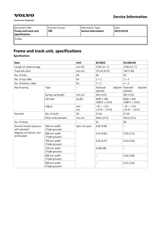
Frame and track unit, specifications
Specifications
Item Unit EC140LC EC140LCM
Length of undercarriage mm (ft) 3740 (12′ 3″) 3790 (12′ 5″)
Track link pitch mm (in) 171.45 (6.75) 190 (7.48)
No. of links EA 46 42
No. of top roller EA 1 × 2 2 × 2
No. of bottom roller EA 7 × 2 6 × 2
Type – Hydraulic adjuster
(grease)
Hydraulic adjuster
(grease)
Recoil spring
Spring, set length mm (in) 405 (15.9) 405 (15.9)
Set load kg (lb) 8560 ± 685
(18872 ± 1510)
8560 ± 685
(18872 ± 1510)
Adjust mm
(in)
–20 ~ +115
(–0.79 ~ +4.53)
–20 ~ +115
(–0.79 ~ +4.53)
No. of tooth EA 21 EA 21 EA
Sprocket
Pitch circle diameter mm (in) 644.6 (25.3) 644.6 (25.3)
No. of shoes – 92 84
500 mm width
(Triple grouser)
0.40 (5.68) –
Ground contact pressure
with standard
digging unit (boom, arm
and bucket)
kgf / cm2 (psi)
600 mm width
(Triple grouser)
0.34 (4.84) 0.36 (5.12)
700 mm width
(Triple grouser)
0.30 (4.27) 0.32 (4.56)
750 mm width
(Triple grouser)
0.28(3.98) –
800 mm width
(Triple grouser)
– 0.28 (3.98)
900 mm width
(Triple grouser)
– 0.25 (3.56)
2. Service Information
Document Title: Function Group: Information Type: Date:
Superstructure, installation 710 Service Information 2015/10/28
Profile:
Superstructure, installation
1.
2.
3.
4.
Bundle the hoses attached to the center passage together and place them upright.
Coat the screws and threaded holes of the slew ring with "Three bond 1215" (Loctite #515).
Figure 1
Fig. 5 Installing the superstructure
Lift the superstructure and install it to the slew ring.
NOTE!
Lower the superstructure so that the slew pinion and the slew ring are engaged.
NOTE!
For tightening torque, refer to the torque chart.
NOTE!
Tighten diagonally opposite screws in sequence.
Connect the hoses, center passage clamping screw and seal cover disconnected for removal.
3. Service Information
Document Title: Function Group: Information Type: Date:
Superstructure, removal 710 Service Information 2015/10/28
Profile:
Superstructure, removal
WARNING
The superstructure weigh approximately 4 ~ 7 tons (excluding counterweight and digging units). Pay attention to
safe footing and the area around the crane before proceeding to remove or install the superstructure.
1.
2.
3.
4.
5.
Remove the digging unit.
Disconnect center passage clamping screw, seal cover, hydraulic oil hoses, drain hose, and one servo hydraulic oil
hose from center passage.
NOTE!
Bundle the hoses. Blind plug each disconnected hose and pipe.
Remove screws (A) fixing the outer race of the slew ring.
Figure 1
Slew ring installed
B. Confirm alignment of match–marks
Dismantle the cab, counterweight and guard. Place a wire rope on the superstructure and lift it with a crane to an
extent that the wire rope is not slack.
Figure 2
Lifting the superstructure
Lift the superstructure just a little, and after confirming safety all around, lift it up and out.
4. Service Information
Document Title: Function Group: Information Type: Date:
Additional counterweight
& digging
unit
716 Service Information 2015/10/28
Profile:
Additional counterweight & digging unit
When special digging units (such as: scrap handling clam, log loader etc.,) are installed on the excavators, an additional
counterweight is required for stability.
In these cases, check the digging unit specification and compare it carefully to the excavator load lifting capacity chart.
And if in doubt, contact your local dealer for advice.
Additional counterweight can be installed according to special digging units, however we are not responsible for any failure
of the excavator or breakage of digging units due to such application.
For reference, an excavator is basically designed only for excavating and is not designed to be used as a crane.
5. Service Information
Document Title: Function Group: Information Type: Date:
Undercarriage, description 7181 Service Information 2015/10/28
Profile:
Undercarriage, description
Undercarriage consists of idlers, spring package, top and bottom rollers, sprockets, track links, track frame and track guards.
Figure 1
Structure, undercarriage
1 Track frame 3 Top roller 5 Spring package 7 Bottom roller
2 Idler 4 Track link 6 Track guard 8 Sprocket
7. Service Information
Document Title: Function Group: Information Type: Date:
Selection of track shoes 775 Service Information 2015/10/28
Profile:
Selection of track shoes
Choose suitable track shoes to match the ground conditions.
Method of selecting shoes
Confirm the category from the list of uses in the table [Invalid linktarget] , then use the table [Invalid linktarget] to select the
shoe.
Categories “B” is wide shoe, so there is restrictions on their use.
Therefore, before using, check the restrictions and consider carefully the conditions of use before selecting a suitable shoe
width. If necessary, give the customer guidance in their use.
When selecting the shoe width, select the narrowest possible within the range that will give no problem with flotation and
ground pressure. If a wider shoe than necessary is used, there will be a large load on the shoe, and this may lead to bending
of the shoe, cracking of the links, breakage of the pins, loosening of the shoe screws, or other problems.
Category, track shoes
Category Use Precautions when using
A Rocky ground, normal soil Travel in low speed when traveling on rough ground with obstacles such as
large boulders and fallen trees.
B Soft ground Travel in high speed only on flat ground. When it is impossible to avoid
traveling over obstacles, lower the travel speed to approximately half of low
speed.
CAUTION
Cannot be used on rough ground where there are large obstacles such as
boulders and fallen trees.
C Extremely soft ground
(swamp ground)
Use only for ground where “A” and “B” are impossible to use.
Travel in high speed only on flat ground. When it is impossible to avoid
traveling over obstacles, lower the travel speed to approximate half of low
speed.
CAUTION
Cannot be used on rough ground where there are large obstacles such as
boulders and fallen trees.
Selection, track shoes
Specification EC140LC EC140LCM
500 mm grouser A –
600 mm grouser A A
700 mm grouser B B
750 mm grouser B –
800 mm grouser – C
900 mm grouser – C
8. Service Information
Document Title: Function Group: Information Type: Date:
Idler, assembly 7751 Service Information 2015/10/28
Profile:
Idler, assembly
Assemble in the reverse order of disassembly.
1.
2.
3.
4.
5.
6.
7.
8.
9.
Place bushing (4) on idler wheel (1), and using jig (h), force fit with press (a).
Figure 1
Location to be inspected
Install o-ring (9) on shaft (2).
Figure 2
Assembly, o-ring and etc.
Apply a thin coat of grease to inner side of support (3), install shaft (2), and insert spring pin (7). In this case, take
care not to damage o-ring (9).
Insert seal ring (5) and o-ring (6) to the support (3) and idler wheel (1), respectively.
Install shaft (2) to idler (1). Lightly coat engine oil on seal ring (5) contact face.
Figure 3
Assembly, shaft
Install support (3) with seal ring (5) and o-ring (6) to idler wheel (1).
Insert pin (7) with hammer (k).
Fill with engine oil (j).
EC140LC EC140LCM
Oil capacity 260 cc (15.9 cu·in) 365 cc (16.4 cu·in)
Install plug (8) with teflon tape (L), and tighten securely.
Inspection after assembly
1. Confirm that there are no oil leaks around seals (5, 6) and plug (8).
9. 2.
3.
4.
Assemble the idler assembly and track spring. After assembling, manually confirm that idler (1) rotates to the extent
you can rotate it despite the resistance. (More than 10 times).
Figure 4
Assembly, idler and track spring
Apply loctite #277 to screw A
Tightening torque: 28.5 ± 3 kgf·m (206 ± 2 lbf·ft)
Prior to filling with oil perform a pressure leak test. – Attach a pressure regulated air line to the oil fill port, then
completely immerse the assembly in water. – Under a pressure of 2 ~ 3 kgf/cm2 (28 ~ 43 psi), air bubbles must not
form for 15 seconds.
End play must be within 0.1 to 0.6 mm.
10. Service Information
Document Title: Function Group: Information Type: Date:
Idler, description 7751 Service Information 2015/10/28
Profile:
Idler, description
Figure 1
Structure, idler
1 Idler wheel 6 O-ring
2 Shaft 7 Pin
3 Support 8 Plug
4 Bushing 9 O-ring (shaft)
5 Seal ring
11. Service Information
Document Title: Function Group: Information Type: Date:
Idler, disassembly 7751 Service Information 2015/10/28
Profile:
Idler, disassembly
The numbers in parentheses following each part name in the text correspond to those in figure.
1.
2.
3.
4.
5.
Remove the screws, and remove the track spring.
Figure 1
Removal, track spring
Remove plug (8) to drain oil.
Put pin jig (d) on pin (7), and force out the pin by lightly tapping the jig with a hammer.
Figure 2
Removal, pin
Place idler (1) on idler support jig (f), put shaft removal jig (g) on shaft (2) and force out the shaft using press(a).
Figure 3
Push with a press
Place idler (1) on idler support jig (f), put bearing assembly jig (h) and bushing removal jig (e) on bushing (4), and
drive out the bushing by lightly tapping the jig.
12. 6.
7.
Figure 4
Removal, bushing
Remove seal ring (5) and o-ring (6) from idler wheel (1) and support (3), respectively.
Remove o-ring (9) from shaft (2).
Inspection after disassembly
1.
2.
3.
Confirm that there is no damage or rust on the sealing face of seal (5).
Confirm that any wear of idler (1) is within the allowable range.
Confirm that any wear of shaft (2) or bushing (4) is within the allowable range.
13. Service Information
Document Title: Function Group: Information Type: Date:
Idler, installation 7751 Service Information 2015/10/28
Profile:
Idler, installation
Installation of the idler and the track spring
1.
2.
3.
Tighten connecting screws (1) of idler and track spring.
Pass a wire rope around the track spring bracket, lift the idler assembly, then fit and push the slide block into the
slide groove in the track frame.
CAUTION
Confirm that the boss at the piston end of the track spring is in the track frame hole
Figure 1
Install, idler assembly
Install the track.
Figure 2
Installation, track
14. Service Information
Document Title: Function Group: Information Type: Date:
Idler, measurement of wear
(EC140LC)
7751 Service Information 2015/10/28
Profile:
Idler, measurement of wear (EC140LC)
Figure 1
Measurement, wear
Limit of wear (EC140LC), unit: mm (in)
No. Check item Standard size Repair limit Remedy
1 Outer diameter of flange 540 (21.3) – Reinforcement
welding or replace
2 Outer diameter of tread 495 (19.5) 483 (19.0)
3 Width of flange 68 (2.7) 60 (2.4)
4 Total width of tread 135 (5.3) –
5 Width of tread 33.5 (1.3) 40 (1.6)
Tolerance Clearance
6 Clearance between shaft
and bushing
Standard
size
Replace bushing
Shaft Hole Standard Repair
limit
70 0
–0.03
+0.35
+0.30
0.3
~0.38
1.5
7 Clearance between shaft
and support
78 +0.132
+0.102
+0.064
0
0.038
~0.132
– Replace bushing
15. Thank you very much for
your reading. Please Click
Here. Then Get COMPLETE
MANUAL. NO WAITING
NOTE:
If there is no response to
click on the link above,
please download the PDF
document first and then
click on it.
16. Service Information
Document Title: Function Group: Information Type: Date:
Idler, removal 7751 Service Information 2015/10/28
Profile:
Idler, removal
Removal of the idler and the track spring
1.
2.
3.
Remove the track.
Pass a wire rope around the track spring bracket, lift the idler assembly, and push the bracket out of the track frame
using a pry bar.
Figure 1
Removal, idler assembly
Remove connecting screws (1) of idler and track spring.
Figure 2
Removal, connecting screw
17. Service Information
Document Title: Function Group: Information Type: Date:
Idler, tools for disassembly
and assembly
7751 Service Information 2015/10/28
Profile:
Idler, tools for disassembly and assembly
Prepare the following tools for disassembly and assembly.
Tools, unit: mm
Symbol Tools Remark
a Press 20 ton class (44000 lbs)
b Grease gun
c Torque wrench 60 kgf·m (433 lbf·ft)
d Pin jig
e Bushing driver jig
f Idler support jig
φ A: φ 280 (EC140LC), φ 500 (EC140LCM)
φ B: φ 300 (EC140LC), φ 520 (EC140LCM)
g Shaft extruding jig
h Bushing assembly jig
φ A: φ 58 (EC140LC), φ 68 (EC140LCM)
φ B: φ 66 (EC140LC), φ 75 (EC140LCM)
j Engine oil SAE 10W–30
k Hammer
L Teflon tape 1 Roll
18. Service Information
Document Title: Function Group: Information Type: Date:
Sprocket, installation 7752 Service Information 2015/10/28
Profile:
Sprocket, installation
The installation procedure is reverse order of removal.
1.
2.
Install the sprocket on the track gearbox.
Apply loctite #277 to the sprocket screws (C), and tighten them to the specified torque.
Figure 1
Screw in, screws
Tightening torque: 28.5 ± 3 kgf·m (266 ± 22lbf·ft)
19. Service Information
Document Title: Function Group: Information Type: Date:
Sprocket, measurement
of wear
7752 Service Information 2015/10/28
Profile:
Sprocket, measurement of wear
Figure 1
Sprocket
Wear limit, unit: mm (in)
Symbol Item EC140LC EC140LCM Remedy
A Wear limit of sprocket tooth profile 6 (0.24) 6 (0.24) Replace
Standard value 58 ± 2 (2.28 ± 0.08) 70 ± 2 (2.76 ± 0.08)
B Width of
sprocket tooth Allowable value 50 (1.97) 62 (2.44)
C Number of teeth 21 EA 21 EA –
20. Service Information
Document Title: Function Group: Information Type: Date:
Sprocket, removal 7752 Service Information 2015/10/28
Profile:
Sprocket, removal
1.
2.
3.
Remove the track.
Place a wooden block (W) on the track, and place the undercarriage on the block to raise the sprocket off the track.
Remove the sprocket mounting screw (C), using a socket wrench.
Figure 1
Removal, sprocket