The document provides a timeline and history of releases for both Autodesk's AutoCAD and ESRI's ArcGIS software. It discusses the transition from earlier CAD-based systems to newer GIS-based systems. It also provides tips and considerations for converting CAD data, such as thorough documentation and inspection of layers, into a geodatabase format within ArcGIS.
MicroStation DGN: How to Integrate CAD and GISSafe Software
See how to move data between Bentley MicroStation and GIS solutions like Esri ArcGIS, Intergraph and MapInfo. Go beyond basic CAD / GIS conversion and see how to transform MicroStation cells, text, lines, symbology, tags, etc exactly as needed. Plus see how to reproject to any coordinate system and use automated techniques to handle database links and provide self-serve data collection and validation services.
Preparation of planning documents for instrumentation, power plants and control but also installation and process measuring and control technology are in the competence of the electric design engineer. The common data base permits at any time the access to information about all trades involved in the project such that planning of electrical engineering can be combined with planning of process engineering.
See how to perform more sophisticated CAD-GIS transformations with FME 2016. We’ll look at topics like attribute validation, automated AutoCAD layout creation for tiled datasets, and more.
Taming Our Case Management Database and GIS with FMESafe Software
With a strong economy and a rapidly growing urban area, Austin attracts considerable development interest. Some of the key indicators of future changes in the built environment include the applications for site plans, subdivisions, and zoning changes which are filed with the City of Austin for approval. Processing this information is vital in understanding changes in land use, and developing strategies to plan for the impacts of incoming development. This presentation will look at how the City of Austin leveraged FME to create a process to automate the creation and publication of geospatial and non-geospatial datasets for applications for site plans, subdivisions and zoning changes to disseminate information to the public as well as other city departments and organizations.
FME is typically used to exchange data, but it can also be used as a powerful tool to automate the transformation of spatial data into technical CAD diagrams. In this presentation I will show how I embedded FME into an application process to create on-the-fly AutoCAD diagrams for communication manholes. This involves determining the local spatial reference, calculating the extents required, clipping the data, creating labels for the data, filtering the data to set line colors and styles, and then exporting the file using linked workspaces.
Automated Bulk Conversion of 250,000+ CAD and Corresponding Raster Files to PDFSafe Software
This presentation will describe the process and results of a contracting project that utilized both FME Desktop and FME Server to combine more than 250,000 DGN files and associated rasters and referenced border files into PDF files that can be easily viewed via mobile devices. The purpose of the project was to provide the client with an automated process that enables mobile access to their Substation, Transmission, and Business Protection designs.
ArcGIS Data Interoperability: Tips for LiDAR, 3D, and BIMSafe Software
Discover how to master 3D data and ArcGIS using the Data Interoperability extension. Learn more about transforming LiDAR point clouds, creating 3D buildings from 2D geometries, and converting BIM data formats in ArcGIS for optimal visualization and analysis.
5 Tips for Integrating CAD Data with Esri ArcGISSafe Software
Converting between CAD and GIS can be a contorted, convoluted task. But it doesn’t have to be. Learn how you can integrate your CAD data with ArcGIS while preserving rich CAD symbology and GIS attribution details. Plus, see how you can automate conversion and validation processes.
The City of Santa Rosa Utilities Department uses FME for key GIS data processing and integration tasks that support several city-wide asset management initiatives. For example, FME is used to convert data from/to CAD, Enterprise Geodatabase, SQL, Access, shapefile and other formats. FME proved to be a vital component in a recent project involving loading a new Enterprise Geodatabase from CAD and prepping that data for integration with a Hansen Maintenance Management System in SQL for Sewer and Water infrastructure. This presentation will highlight the role FME plays within these projects, as well as other Asset Management applications.
I:Autocad
is a full featured collection of software tools used for designing and drafting.
Developed by Autodesk, Inc. (Mill Valley, California)
Released in December, 1982
II:Reasons why use Autocad
-Accurate
-Productive and efficient
-Capable of sharing data
III:Drawing Commands
Keystrokes -Commands
l -Line
pl -Polyline
rec -Rectangle
c - Circle
a -Arc
el -Ellipse
pol- Polygon
e -Erase
m -Move
co -Copy
ar -Array
ro -Rotate
tr -Trim
ex- Extend
o- Offset
s -Stretch
mi -Mirror
f -Fillet
cha -Chamfer
J- Join
Br -Break
sc -Scale
po -Point
spl -Spline
la -Layer
mt -Mtext
dim -Dimension
h -Hatch
ch -Properties
lw -Line weight
IV:Entering points in Autocad
-Absolute coordinates
-Relative rectangular coordinates / relative coordinates
-Relative polar coordinates / polar coordinates
V:2 Types of Array
-Rectangular array
-Polar array
VI:Layer properties
-Status
-Name
-On
-Freeze
-Lock
-Color
-Linetype
-Lineweight
-Plot style
-Plot
-Description
VII:Dimension
a.Basic Types:
-Linear
-Angular
-Radial
-Ordinate
-Arc length
b.Parts of Dimension:
-Dimension text
-Dimension line
-Arrowheads
-Extension line
-Center mark
-Center lines
Using FME to Validate CAD File Submittals for UtilitiesSafe Software
In an effort to speed the process of entering proposed developer infrastructure into it's geospatial database, the City of Henderson Department of Utility Services recently began requiring civil engineering designs to be submitted electronically using CAD files following newly developed CAD standards. The City teamed with Consortech to create an FME Workbench to automate validation processing and generate a report to let users know how well the CAD file adheres to the City standards. This presentation will show the results of this FME automated CAD validation project.
Bridging Between CAD & GIS: 8 Ways to Automate Data IntegrationSafe Software
Converting between CAD and GIS is a common requirement for projects involving infrastructure, buildings, city plans, and more. Unfortunately, the workflow presents many challenges, like translating geometry, attributes, annotations, symbology, geolocation, and other elements.
So how do you allow data to flow freely between these disparate data types, without losing the precision offered by CAD and the spatial context offered by GIS?
This webinar will explore the power of automated data integration workflows for CAD and GIS.
First, we’ll discuss challenges and scenarios for CAD-to-GIS translations, and demo how to use FME to power a digital plan submission portal that validates CAD data and integrates it into the central GIS repository. Next, we’ll discuss challenges and scenarios for GIS-to-CAD conversions, and demo how to build an automated FME workflow for requesting CAD data from GIS.
At the end of the webinar, you'll know how to achieve harmony between CAD & GIS by automating its integration.
How to Exchange Data between CAD and GISSafe Software
Gain total control over CAD and GIS data exchange. Discover how to use FME to preserve the information in CAD annotation when converting to GIS, and turn GIS data and attributes into rich, clean CAD drawings. You'll see how you can use reusable workflows to easily transform virtually any CAD or GIS data including AutoCAD, Esri ArcGIS, MapInfo, and MicroStation.
From Outdoor to Indoor: 3D and Venue Mapping – FME Summer CampSafe Software
Indoor mapping is an exciting new opportunity for business, but it does not come without challenges. With complex data conversion, the merging of spatial and tabular data, and the added difficulty of changing venues, it can turn any venue into a Mess Hall. By adding new Readers and Writers to FME 2018–including IMDF–we're making it easy for you to validate, update, automate, and analyze indoor mapping data.
NE developed this workflow to assist the GIS - CAD data integration and to disseminate data access outside of the GIS group. A geodatabase is created to organize the cad drawings (DWG) while giving non-GIS users access via a webmap, and the ability to export specific project areas to a DWG format.
Before this solution, our DWG files were stored using their respective project number as their names; management noticed that drafters were working on areas where we had previously worked, but instead of reusing the latest DWG files, they were drafting the project from scratch, resulting in a non-optimized workflow.
This presentation was given at GIStech 2010 in Rotterdam (NL) and later to students of the University of Wageningen. In this presentation we explain the choices we've made in a number of GIS projects.
Converting between CAD and GIS is a common requirement for projects involving infrastructure, buildings, city plans, and more. Unfortunately, the workflow presents many challenges, like translating geometry, attributes, annotations, symbology, geolocation, and other elements. So how do you allow data to flow freely between these disparate data types, without losing the precision offered by CAD and the spatial context offered by GIS?
This webinar will explore the power of automated data integration workflows for CAD and GIS. First, we’ll discuss challenges and scenarios for CAD-to-GIS translations, and demo how to use FME to power a digital plan submission portal that validates CAD data and integrates it into the central GIS repository. Next, we’ll discuss challenges and scenarios for GIS-to-CAD conversions, and demo how to build an automated FME workflow for requesting CAD data from GIS.
How to Overcome 7 Top AutoCAD Road 'Blocks'Safe Software
Learn techniques for solving 7 common AutoCAD challenges. First, discover how to perform high-fidelity data exchange between AutoCAD and Esri ArcGIS. Next, see how to sync your AutoCAD design with external data sources – including databases, GPX, and CSV – and then automatically label any new inputs, such as with parcels. Plus see how to restructure between CAD standards and perform automated QA on your data.
Bridging Between CAD & GIS: 8 Ways to Automate Data IntegrationSafe Software
Converting between CAD and GIS is a common requirement for projects involving infrastructure, buildings, city plans, and more. Unfortunately, the workflow presents many challenges, like translating geometry, attributes, annotations, symbology, geolocation, and other elements.
So how do you allow data to flow freely between these disparate data types, without losing the precision offered by CAD and the spatial context offered by GIS?
This webinar will explore the power of automated data integration workflows for CAD and GIS.
First, we’ll discuss challenges and scenarios for CAD-to-GIS translations, and demo how to use FME to power a digital plan submission portal that validates CAD data and integrates it into the central GIS repository. Next, we’ll discuss challenges and scenarios for GIS-to-CAD conversions, and demo how to build an automated FME workflow for requesting CAD data from GIS.
At the end of the webinar, you'll know how to achieve harmony between CAD & GIS by automating its integration.
Bridging Between CAD & GIS: 8 Ways to Automate Your Data IntegrationSafe Software
Converting between CAD and GIS is a common requirement for projects involving infrastructure, buildings, city plans, and more. Unfortunately, the workflow presents many challenges, like translating geometry, attributes, annotations, symbology, geolocation, and other elements.
So how do you allow data to flow freely between these disparate data types, without losing the precision offered by CAD and the spatial context offered by GIS?
This webinar will explore the power of automated data integration workflows for CAD and GIS.
First, we’ll discuss challenges and scenarios for CAD-to-GIS translations, and demo how to use FME to power a digital plan submission portal that validates CAD data and integrates it into the central GIS repository. Next, we’ll discuss challenges and scenarios for GIS-to-CAD conversions, and demo how to build an automated FME workflow for requesting CAD data from GIS.
At the end of the webinar, you'll know how to achieve harmony between CAD & GIS by automating its integration.
Bridging Between CAD & GIS: 6 Ways to Automate Your Data IntegrationSafe Software
Converting between CAD and GIS is a common requirement for projects involving infrastructure, buildings, city plans, and more. Unfortunately, the workflow presents many challenges, like translating geometry, attributes, annotations, symbology, geolocation, and other elements.
So how do you allow data to flow freely between these disparate data types, without losing the precision offered by CAD and the spatial context offered by GIS?
This webinar will explore the power of automated data integration workflows for CAD and GIS.
First, we’ll discuss challenges and scenarios for CAD-to-GIS translations, and demo how to use FME to power a digital plan submission portal that validates CAD data and integrates it into the central GIS repository. Next, we’ll discuss challenges and scenarios for GIS-to-CAD conversions, and demo how to build an automated FME workflow for requesting CAD data from GIS.
At the end of the webinar, you'll know how to achieve harmony between CAD & GIS by automating its integration.
Bridging Between CAD & GIS: 6 Ways to Automate Your Data Integrationmarketing932765
Converting between CAD and GIS is a common requirement for projects involving infrastructure, buildings, city plans, and more. Unfortunately, the workflow presents many challenges, like translating geometry, attributes, annotations, symbology, geolocation, and other elements.
So how do you allow data to flow freely between these disparate data types, without losing the precision offered by CAD and the spatial context offered by GIS?
This webinar will explore the power of automated data integration workflows for CAD and GIS.
First, we’ll discuss challenges and scenarios for CAD-to-GIS translations, and demo how to use FME to power a digital plan submission portal that validates CAD data and integrates it into the central GIS repository. Next, we’ll discuss challenges and scenarios for GIS-to-CAD conversions, and demo how to build an automated FME workflow for requesting CAD data from GIS.
At the end of the webinar, you'll know how to achieve harmony between CAD &GIS by automating its integration.
Bridging Between CAD & GIS: 6 Ways to Automate Your Data Integrationmarketing932765
Converting between CAD and GIS is a common requirement for projects involving infrastructure, buildings, city plans, and more. Unfortunately, the workflow presents many challenges, like translating geometry, attributes, annotations, symbology, geolocation, and other elements.
So how do you allow data to flow freely between these disparate data types, without losing the precision offered by CAD and the spatial context offered by GIS?
This webinar will explore the power of automated data integration workflows for CAD and GIS.
First, we’ll discuss challenges and scenarios for CAD-to-GIS translations, and demo how to use FME to power a digital plan submission portal that validates CAD data and integrates it into the central GIS repository. Next, we’ll discuss challenges and scenarios for GIS-to-CAD conversions, and demo how to build an automated FME workflow for requesting CAD data from GIS.
At the end of the webinar, you'll know how to achieve harmony between CAD & GIS by automating its integration.
Let's integrate CAD/BIM/GIS on the same platform: A practical approach in rea...SANGHEE SHIN
I gave this keynote talk at 3D GeoInfo conference held at Singapore on 25th September 2019. I shared my experiences in integrating CAD/BIM/GIS on the web platform and introduced mago3D from the technical point of view.
In questa presentazione, tutte le novità e una carrellata completa degli strumenti software del Power Portfolio 2016 di Hexagon Geospatial™.
La release 2016 dei software ERDAS IMAGINE, ERDAS APOLLO, Geomedia e di tutti gli altri strumenti software del Power Portfolio di Hexagon Geospatial è stata presentata ufficialmente il 14 giugno 2016, durante l’evento Hexagon Live di Anaheim (California).
Il Portfolio si compone di tre suite: Producer, Provider e Platform, costituite da prodotti software allo stato dell’arte ed utilizzati in tutto il mondo, che combinano le migliori tecnologie attualmente disponibili nel settore del telerilevamento, della fotogrammetria, del GIS ed in generale per la gestione di dati geospaziali.
Guarda il video e scarica il documento in italiano sulle novità della release 2016 su:
http://www.planetek.it/news_eventi/archivio_news/2016/06/presentato_il_nuovo_power_portfolio_2016_di_hexagon_geospatial
This is a presentation on translating ESRI ArcGIS facilities data to MicroStation CAD format. It shows the translations "out of the box" and then what was necessary to view the GIS data in a MicroStation CAD.
Extending 3D Model Visualization with FME 2017Safe Software
This presentation will give an overview and demonstration of the various expanded capabilities available in FME 2017 to support 3D CAD model loading in Cesiumjs based WebGL viewers such as Burns & McDonnell's geospatial dashboard; OneTouchPM.
A comprehensive set of 3D models have been used to test Civil Engineering use cases in the Utilities, Energy and Transportation sectors. 3D Modeling systems tested include: Revit, AutoCAD, Inventor, MicroStation, OpenRoads, OpenBridge, PLS-CADD, and SketchUp.
Similar to Cad to ESRI Geodatabase Conversion (20)
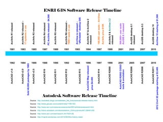
14. Fix misalignment of stacked lines with the Integrate tool Gap Double section lines Integrate tool with .5 foot cluster tolerance will make these lines coincident.
18. 2 Spatial join methods 1) Count field shows number of points within poly 2) Poly receives attributes of closest point. Distance = 0 indicates the point is within the poly boundary.