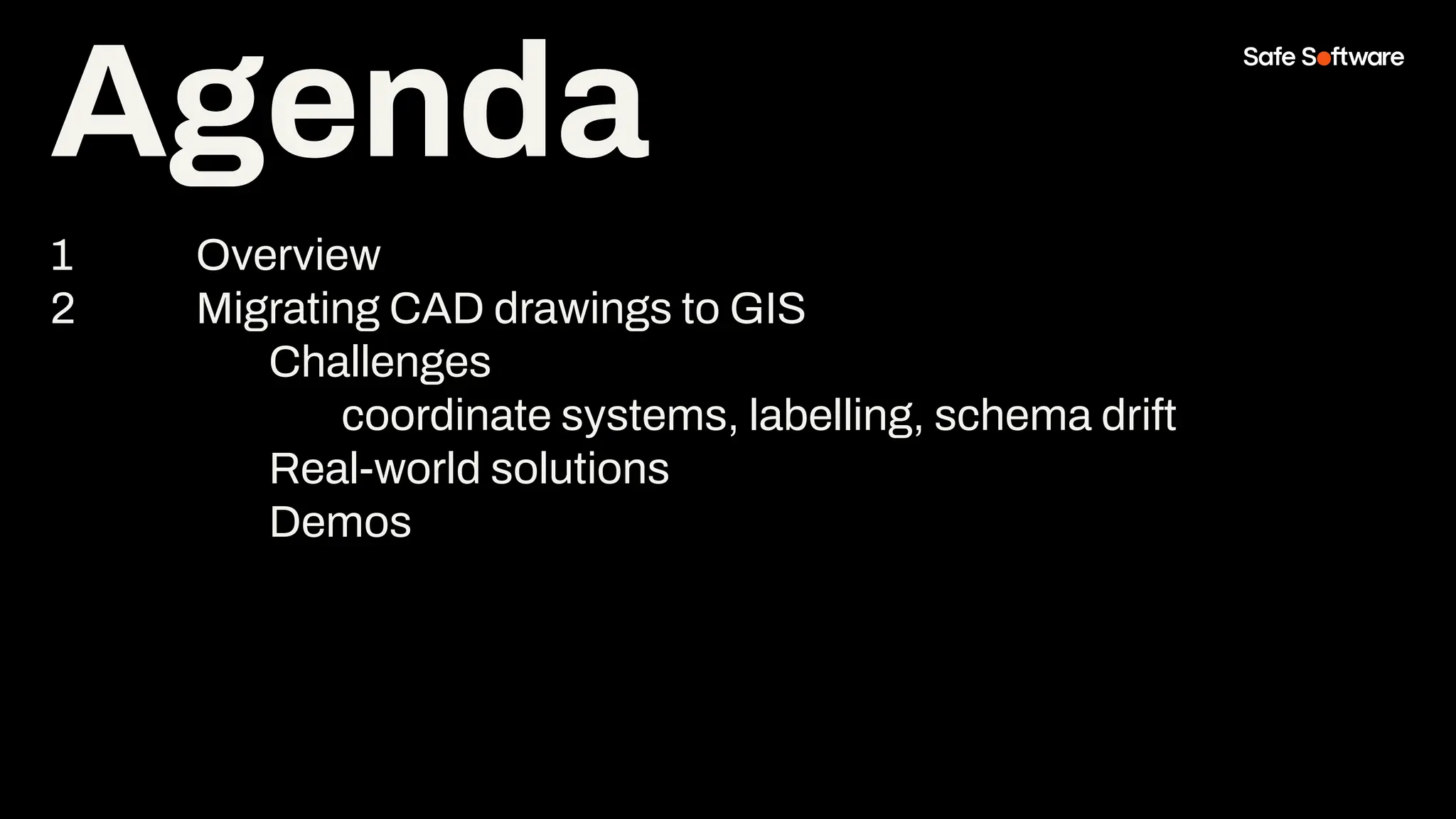
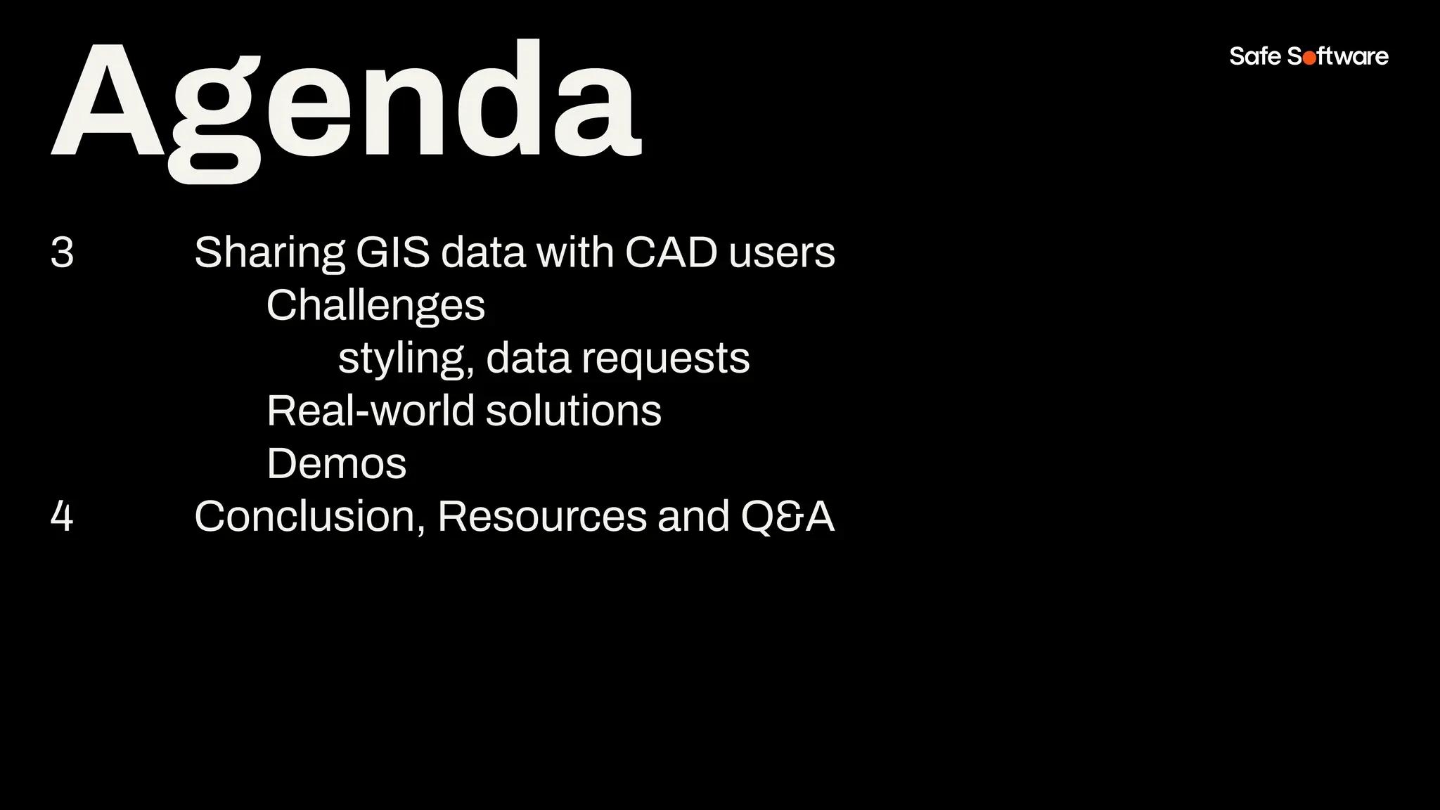
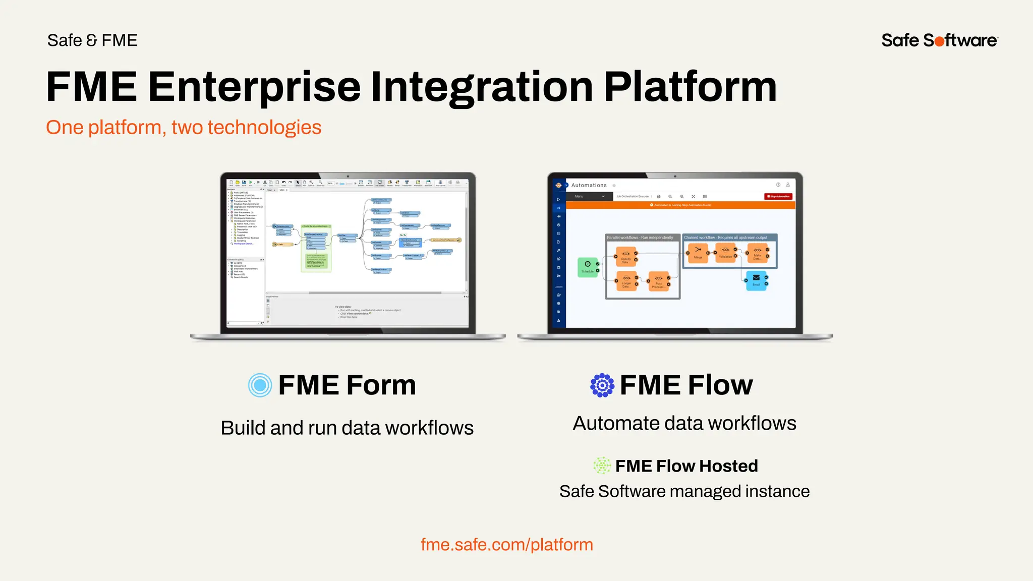
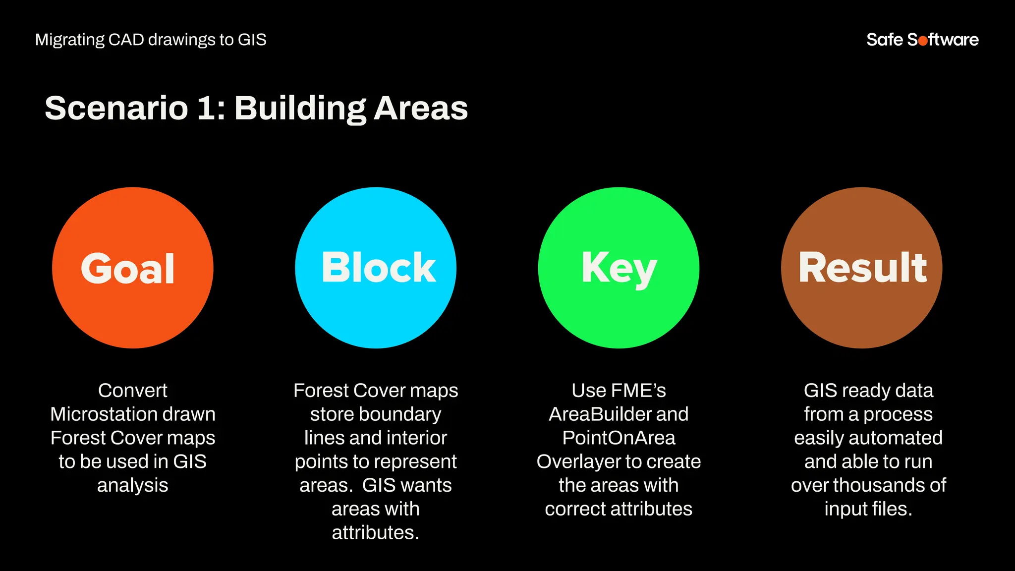
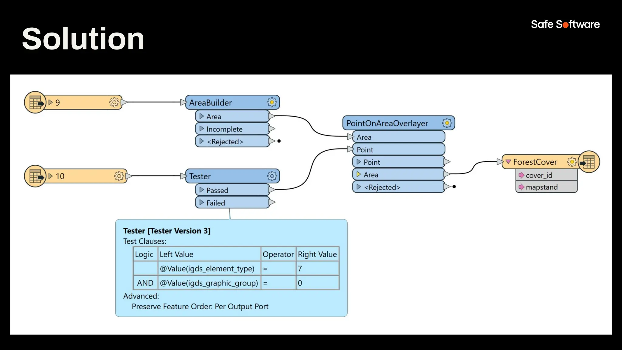
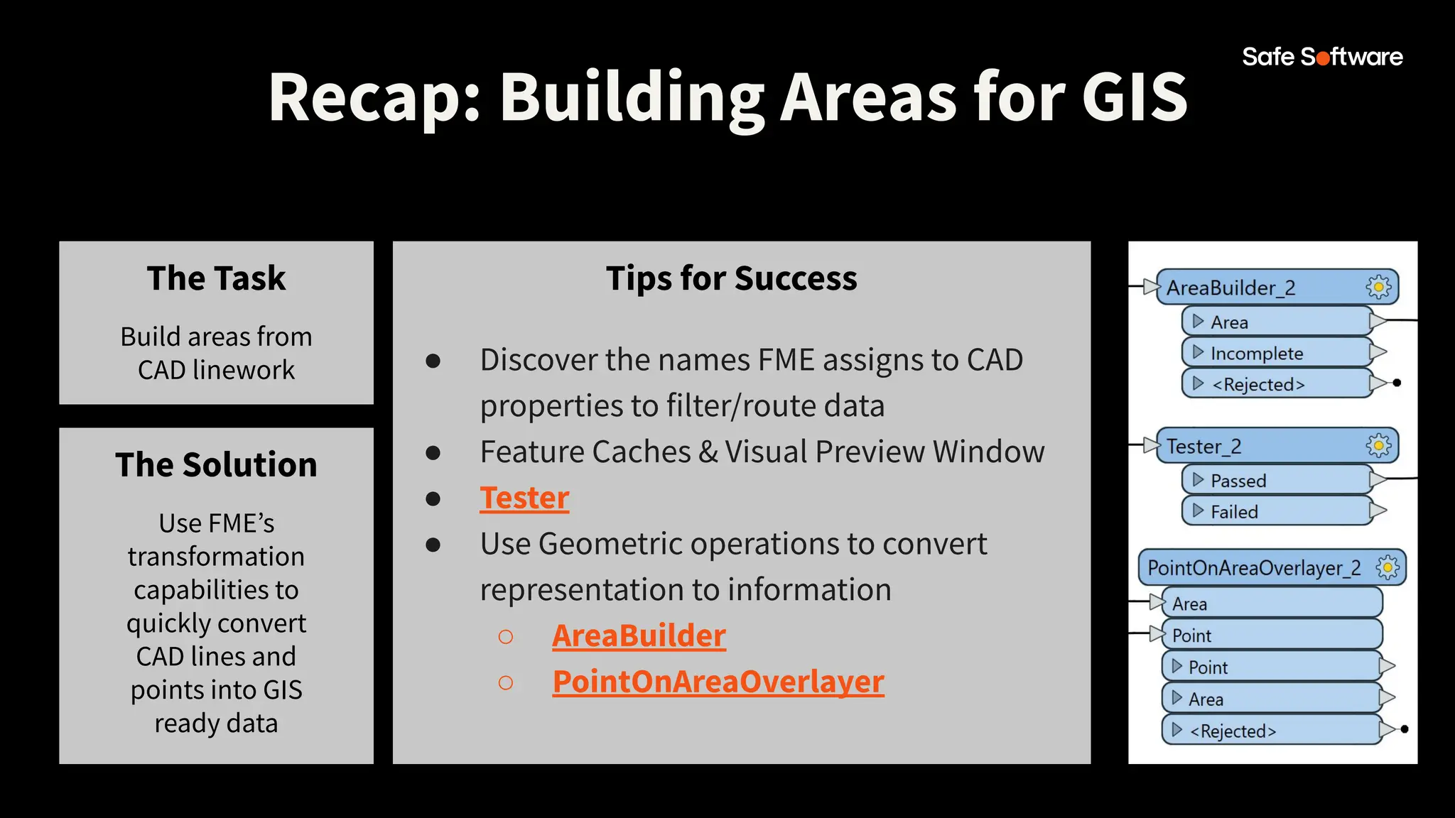
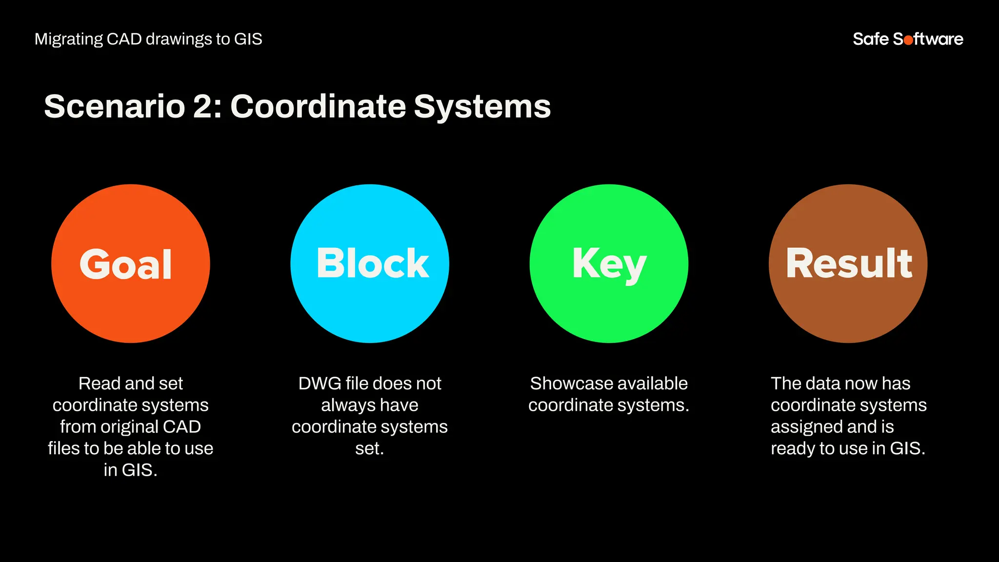
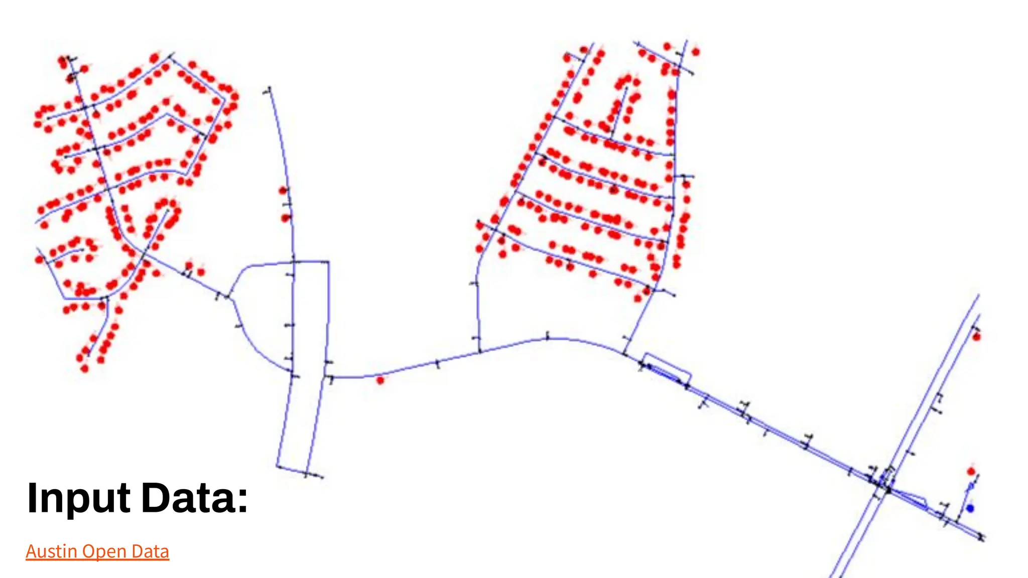
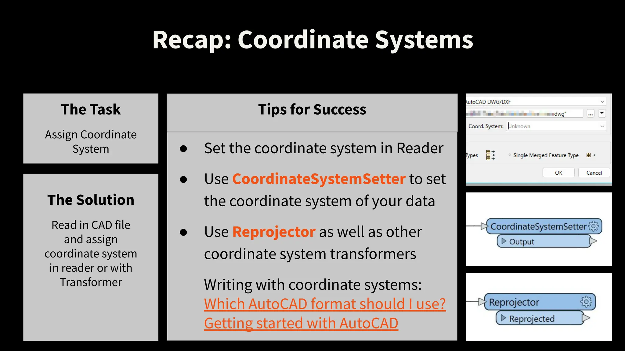
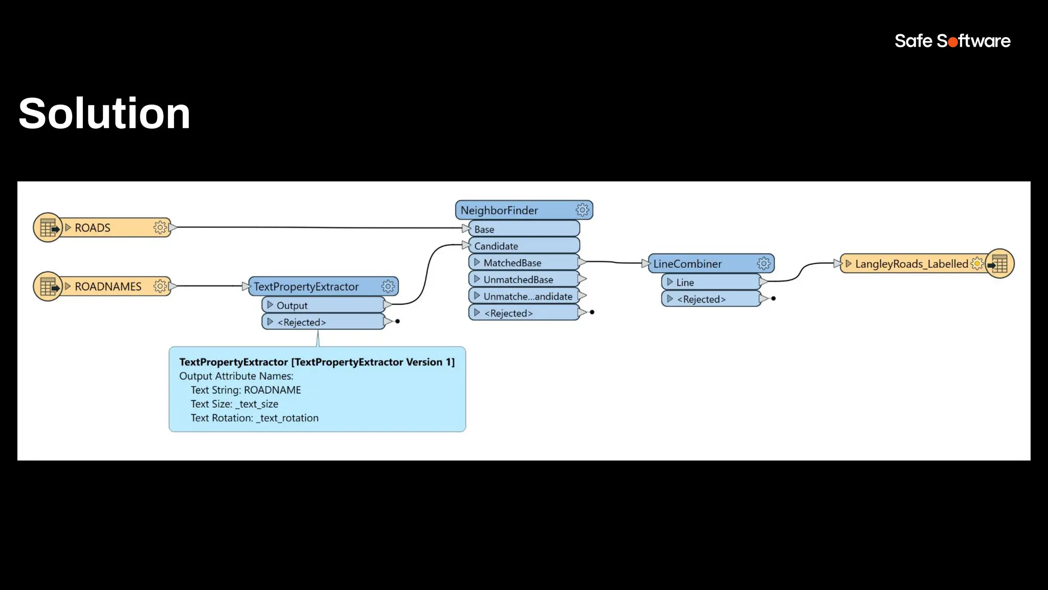
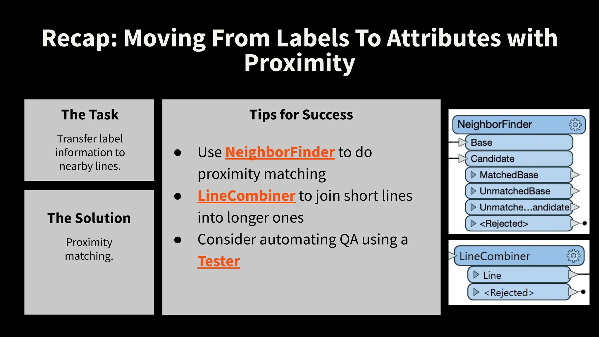
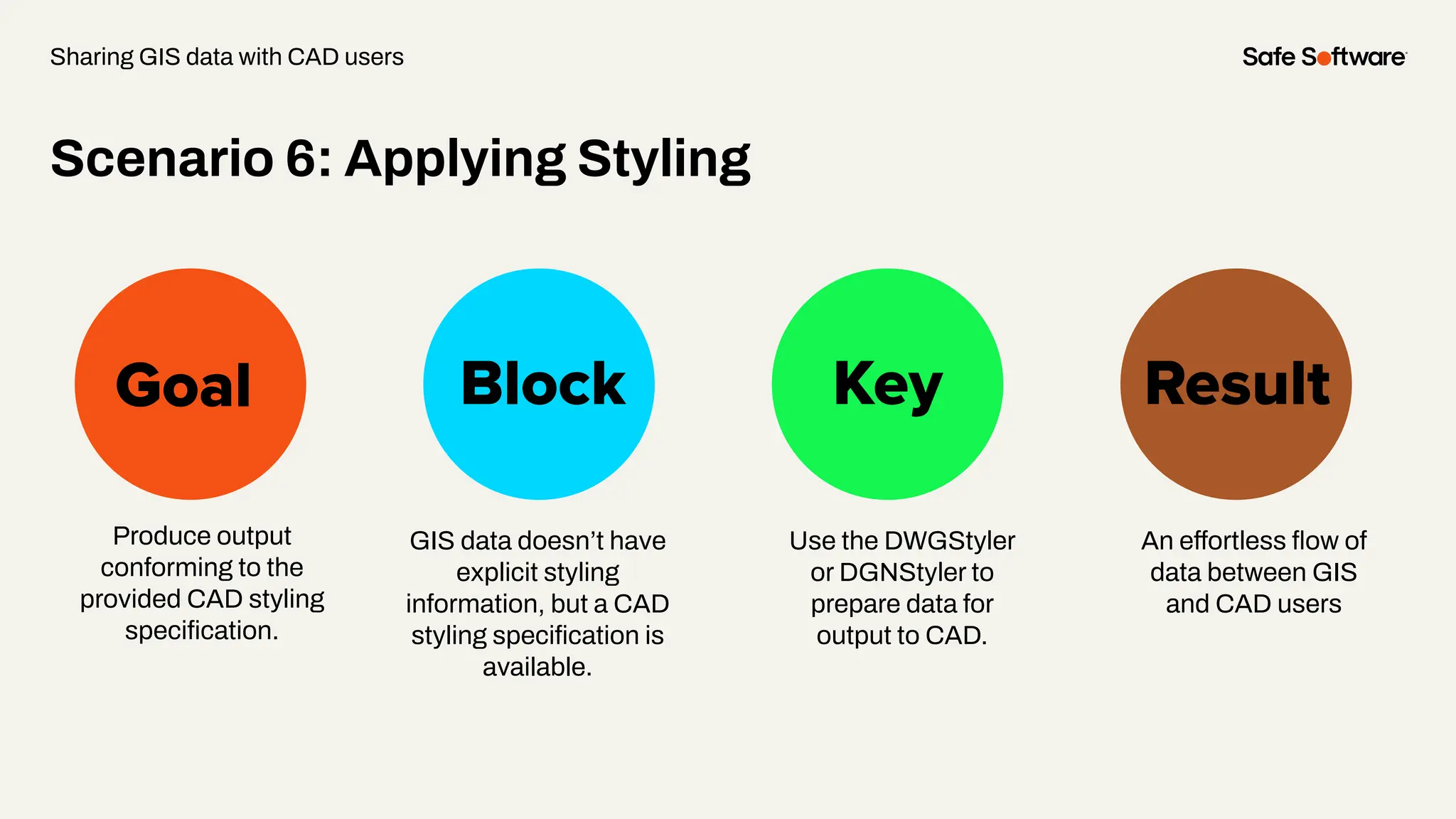
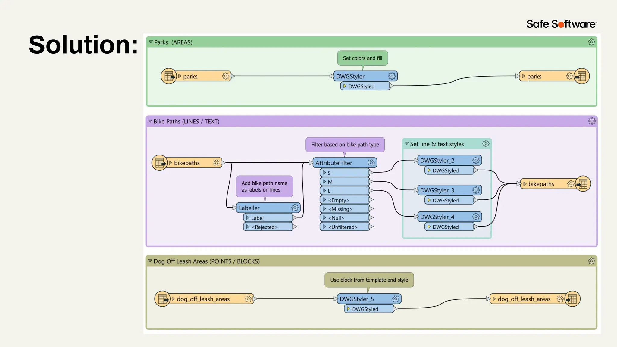
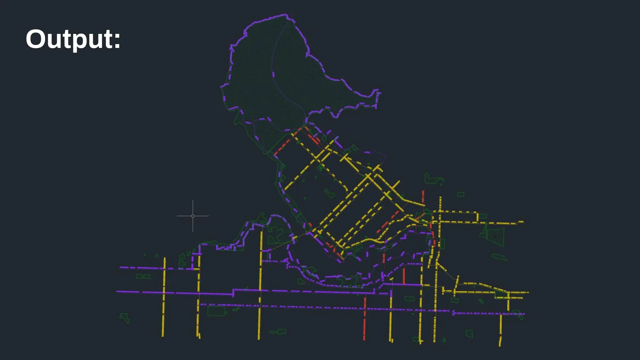
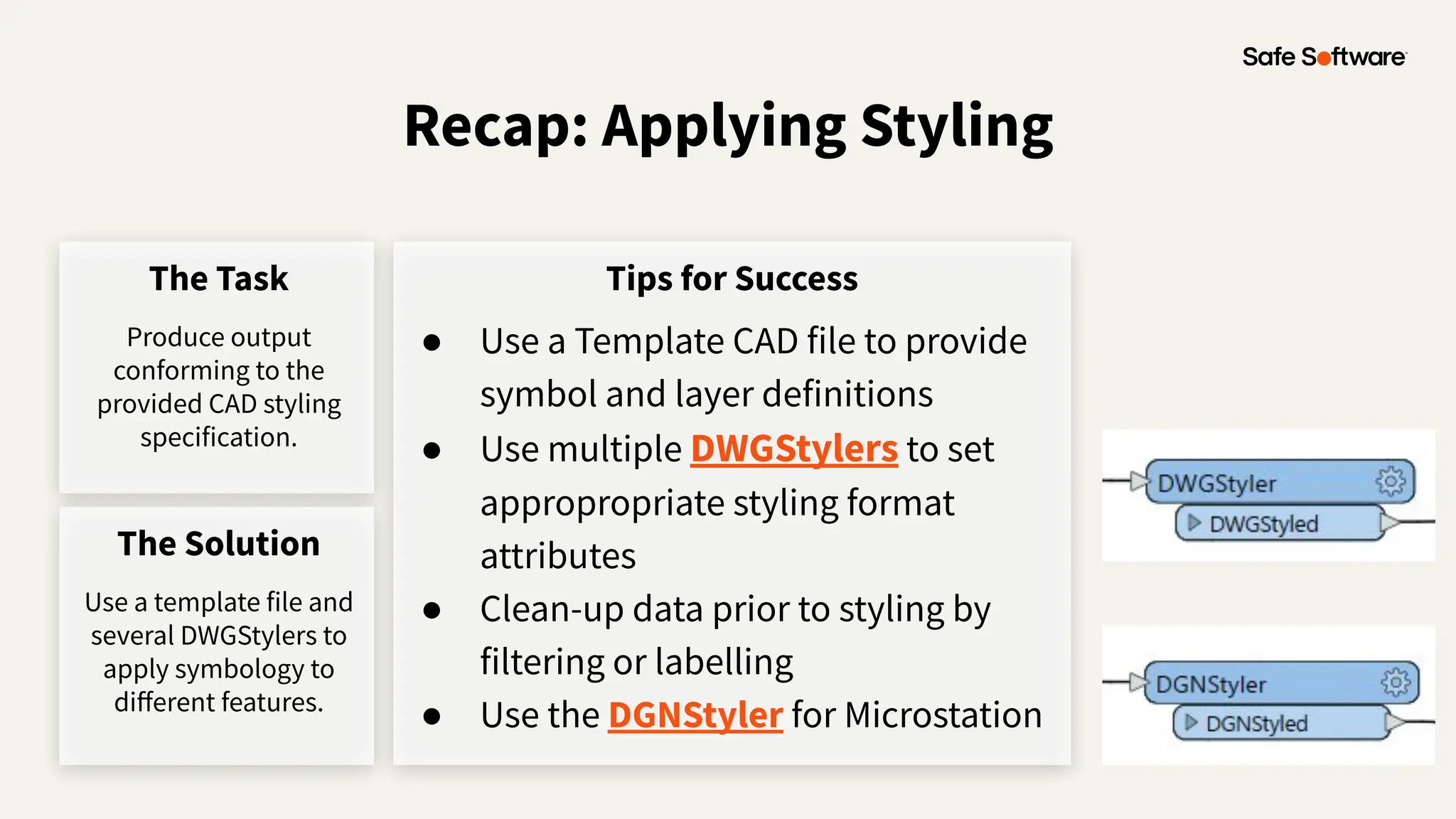
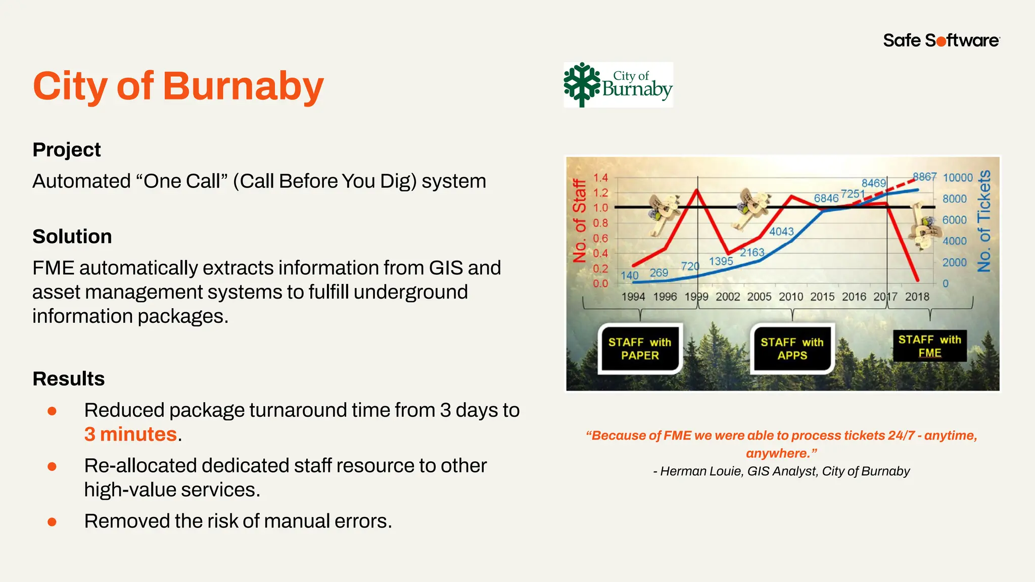
Converting between CAD and GIS is a common requirement for projects involving infrastructure, buildings, city plans, and more. Unfortunately, the workflow presents many challenges, like translating geometry, attributes, annotations, symbology, geolocation, and other elements.
So how do you allow data to flow freely between these disparate data types, without losing the precision offered by CAD and the spatial context offered by GIS?
This webinar will explore the power of automated data integration workflows for CAD and GIS.
First, we’ll discuss challenges and scenarios for CAD-to-GIS translations, and demo how to use FME to power a digital plan submission portal that validates CAD data and integrates it into the central GIS repository. Next, we’ll discuss challenges and scenarios for GIS-to-CAD conversions, and demo how to build an automated FME workflow for requesting CAD data from GIS.
At the end of the webinar, you'll know how to achieve harmony between CAD &GIS by automating its integration.
9. CAD users have a drawing perspective:
● Layers & levels
● Styles & Symbology
● Dimensions & Labels
CAD vs. GIS:
Different Perspectives
Introduction
10. GIS users have a feature perspective:
● Attributes and geometry
● Data structure, model
● Relational tables, domains
● Location (including Coordinate System)
● Connectivity and proximity
● Analysis
CAD vs. GIS:
Different Perspectives
Introduction
12. 29+
27K+
128
190
20K+
years of solving data
challenges
FME Community
members
countries with
FME customers
organizations worldwide
global partners with
FME services
29+
29K+
128
140+
25K+
years of solving data
challenges
FME Community
members
countries with
FME customers
organizations worldwide
global partners with
FME services
200K+
users worldwide
Safe & FME
13. One platform, two technologies
FME Form FME Flow
Build and run data workflows Automate data workflows
FME Flow Hosted
Safe Software managed instance
fme.safe.com/platform
FME Enterprise Integration Platform
Safe & FME
14. Number
of
supported
data
types
in
FME
1995 2000 2005 2010 2015 2020 2023…
10
100
300
500
GIS
CAD
Database
XML
Raster
3D
BIM
Web
Point
Cloud
Cloud
Big
Data
IOT
Gaming
BI
Indoor
Mapping
AR/VR
Generative
AI
Cloud
Native
Tabular
Unrivalled Data Support
17. Goal Block Key Result
Convert
Microstation drawn
Forest Cover maps
to be used in GIS
analysis
Scenario 1: Building Areas
Forest Cover maps
store boundary
lines and interior
points to represent
areas. GIS wants
areas with
attributes.
Use FME’s
AreaBuilder and
PointOnArea
Overlayer to create
the areas with
correct attributes
GIS ready data
from a process
easily automated
and able to run
over thousands of
input files.
Migrating CAD drawings to GIS
24. Recap: Building Areas for GIS
The Task
Build areas from
CAD linework
Tips for Success
● Discover the names FME assigns to CAD
properties to filter/route data
● Feature Caches & Visual Preview Window
● Tester
● Use Geometric operations to convert
representation to information
○ AreaBuilder
○ PointOnAreaOverlayer
The Solution
Use FMEʼs
transformation
capabilities to
quickly convert
CAD lines and
points into GIS
ready data
26. Goal Block Key Result
Read and set
coordinate systems
from original CAD
files to be able to use
in GIS.
Scenario 2: Coordinate Systems
DWG file does not
always have
coordinate systems
set.
Showcase available
coordinate systems.
The data now has
coordinate systems
assigned and is
ready to use in GIS.
Migrating CAD drawings to GIS
31. Recap: Coordinate Systems
The Task
Assign Coordinate
System
Tips for Success
● Set the coordinate system in Reader
● Use CoordinateSystemSetter to set
the coordinate system of your data
● Use Reprojector as well as other
coordinate system transformers
Writing with coordinate systems:
Which AutoCAD format should I use?
Getting started with AutoCAD
The Solution
Read in CAD file
and assign
coordinate system
in reader or with
Transformer
33. Goal Block Key Result
Transfer label
information to
nearby
lines.
Scenario 3: Moving From Labels
To Attributes with Proximity
Containment is not
an option.
Proximity matching
with the
NeighborFinder.
Label information is
transferred to nearby
lines.
Migrating CAD drawings to GIS
38. Recap: Moving From Labels To Attributes with
Proximity
The Task
Transfer label
information to
nearby lines.
Tips for Success
● Use NeighborFinder to do
proximity matching
● LineCombiner to join short lines
into longer ones
● Consider automating QA using a
Tester
The Solution
Proximity
matching.
39. Canʼt Remember 500+
Transformers?
Find your perfect transformer
safe.com/transformers
You donʼt need to!
Use the FME Transformer Gallery.
● Filter by category
● Access it in Workbench
(View > Windows > Transformer Gallery)
● Quick Add in Workbench
40. Canʼt Remember 500+
Transformers?
You donʼt need to!
Use the FME Transformer Gallery.
● Filter by category
● Access it in Workbench
(View > Windows > Transformer Gallery)
● Quick Add in Workbench
42. What is Schema Drift?
Solve more schema drift:
safe.com/webinars
A change in the source or
target data definition.
Usually accompanied by
frustration and time loss.
“Theyʼve added yet another column
to my excel spreadsheet – this
schema drift has got to stop!”
43. Goal Block Key Result
Extract attributes
encoded in CAD layer
names for use in GIS
Schema Drift: Decode Attribute-rich Layer Names
A comprehensive
specification embedded
attributes in parts of the
layer’s name, making it
very hard to understand
or otherwise use the
data.
Split attributes to pick
out the parts, then
apply lookups to
decode to useful
values.
Understandable,
GIS-ready dataset.
Migrating CAD drawings to GIS
44. Layer Name: xxxYYYYMMDDzz
xxx = 3 character code for road type
YYYYMMDD = 8 digits for date of last update
zz = 2 characters to represent collection method
48. Recap: Decode Attribute-rich Layer Names
The Task
Extract attributes
encoded in CAD layer
names for use in GIS
Tips for Success
● AttributeSplitter to break apart the
layer name
● OR use a StringSearcher to extract
values using RegEx
● Decode the parts using a
AttributeValueMapper
● Route to an attribute-rich GIS
dataset
The Solution
Split layer names into
parts, apply lookups to
create understandable
attribute values
50. City of Henderson
Project
Digital Plan Submission
Solution
FME provides self-serve CAD data upload, validation,
and integration into GIS.
Results
● Reduced data integration time by 75%.
● Eliminated the risk of manual error.
● Removed duplicate work.
● Faster processing of submissions.
● Ensured CAD data validation.
“We chose FME for this project because the interface is easy
to use and allows us to provide an adaptable solution to
enhance interaction with the City’s partners.”
- Erika Provost, City of Henderson
51. Goal Block Key Result
Create a digital plan
submission to
automatically check
and upload CAD
drawings to ArcGIS
Online.
Scenario 5: Digital Plan Submission
It takes time and
manual effort to
process development
plans (clean up
geometry, and extract
data), to combine into
GIS data.
Use FME to validate
CAD submissions
before automatically
uploading to ArcGIS
Online.
Submissions that
meet requirements
are uploaded to
ArcGIS Online, and
ones that don’t are
sent back for fixing.
Migrating CAD drawings to GIS
52. Recap: Digital Plan Submission
The Task
Create a digital plan
submission from DWG
to AGOL.
Tips for Success
The Solution
Use FME to check
CAD submissions
for criteria before
automatically
uploading to
ArcGIS Online.
● Preserve labels and attribution from text, blocks or dimensions
● Interpret layers, styles or symbols as attributes
● Improve geometry:
○ Creating connectivity
■ Snapper
■ Intersector
○ Forming areas from lines
■ AreaBuilder
● Combine geometry and attributes using proximity
○ PointOnAreaOverlay
○ NeighborFinder
56. Goal Block Key Result
Sharing GIS data with CAD users
Produce output
conforming to the
provided CAD styling
specification.
GIS data doesn’t have
explicit styling
information, but a CAD
styling specification is
available.
Use the DWGStyler
or DGNStyler to
prepare data for
output to CAD.
An effortless flow of
data between GIS
and CAD users
Scenario 6: Applying Styling
62. Recap: Applying Styling
The Task
Produce output
conforming to the
provided CAD styling
specification.
Tips for Success
● Use a Template CAD file to provide
symbol and layer definitions
● Use multiple DWGStylers to set
appropropriate styling format
attributes
● Clean-up data prior to styling by
filtering or labelling
● Use the DGNStyler for Microstation
The Solution
Use a template file and
several DWGStylers to
apply symbology to
different features.
64. Project
Automated “One Call” (Call Before You Dig) system
Solution
FME automatically extracts information from GIS and
asset management systems to fulfill underground
information packages.
Results
● Reduced package turnaround time from 3 days to
3 minutes.
● Re-allocated dedicated staff resource to other
high-value services.
● Removed the risk of manual errors.
“Because of FME we were able to process tickets 24/7 - anytime,
anywhere.”
- Herman Louie, GIS Analyst, City of Burnaby
City of Burnaby
68. Tutorials in the FME
Community
● GIS to CAD: Convert Parcel Polygons and
Lines from Geodatabase to DGN
● How to Convert DGN to Shapefile (CAD
Levels to GIS Attributes)
● Getting Started with AutoCAD
● Using the Geometry Parameter
Resources
69. Get our Ebook
Spatial Data for the
Enterprise
fme.ly/gzc
Guided learning experiences
at your fingertips
community.safe.com
/s/academy
FME Academy
70. Check out how-to’s & demos
in the knowledge base
community.safe.com
/s/knowledge-base
Knowledge Base Webinars
Upcoming & on-demand
webinars
safe.com/webinars
72. We’d love to help you get
started.
Get in touch with us at
info@safe.com
Experience the FME Accelerator
Contact Us
Unlock the power of your
data in only 90 minutes
Register for free at
fme.safe.com/accelerator
73. ClaimYour Community Badge
● Get community badges for watching
webinars!
● fme.ly/WebinarBadge
● Today’s code: ABWSG
Join the Community today!