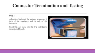
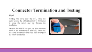
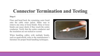
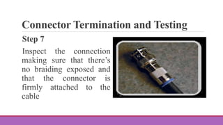
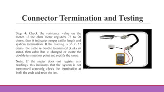
SlideShare a Scribd company logo
1 of 18
Cable Preparation in CCTV
D R . R . H E P Z I P R A M I L A D E V A M A N I
A S S I S T A N T P R O F E S S O R O F P H Y S I C S
V . V . V A N N I A P E R U M A L C O L L E G E F O R W O M E N ,
V I R U D H U N A G A R
Bend Radius
Current coaxial standards do not specify bend radius; however, various manufacturers do provide
guidance. Check with manufacturers for specifics. Special care should be taken when pulling a
coaxial cable around bends. Using too much force or too tight of a bend can deform the dielectric
and cause a drop in transmission performance.
Transmission media is the most important part of an installation. It is estimated that over 65% of
failure in a CCTV system is associated with transmission media which includes the type of cable
used, connectors, connections and the installation methods.
Bend Radius
The second biggest area that account for nearly
27% of the problems are power and
environment related which includes either
excessive or inadequate input power,
ineffective or improper grounding or an
excessive temperature around the equipment.
Incorrect equipment setup, improper
equipment termination and improper camera
installation account for about 7% of the
problems directly associated with the
installation personnel. Only 1% of the failures
in a CCTV installation are actually caused by
device failures.
Connector Termination and Testing
The following steps will guide you through the
preparation and termination process for coaxial
cable with compression connectors.
Following these guidelines will help make sure
that you receive the optimum performance from
the coaxial cable.
Connector Termination and Testing
Step 1
The tools you will need:
Compression tool
Cable stripper
Compression Connectors
Connector Termination and Testing
Step 2
Adjust the blades of the stripper to expose ¼
inch of the conductor and ¼ inch of the
insulation.
Insert the coax cable into the strip cartridge to
the adjusted length.
Connector Termination and Testing
Step 3
Holding the cable near the tool, rotate the
cutter around the cable (three to five full turns)
to score the jacket and cut through the
insulation.
Be sure the braid is cut (you can hear when the
wires of the braid have all been cut). Then flex
the jacket to separate and slide it off to expose
the centre conductor.
Connector Termination and Testing
Step 4
Flare and bend back the remaining outer braid
onto the cable outer jacket. Make sure to
remove any stray or loose braids. Stray or loose
braids can cause shorts if they touch the centre
conductor. Verify that the centre conductor and
the insulation are not nicked or scored.
When handling cables with multiple braids,
such as quad-shield, refer to the manufacturer’s
literature for proper braid handling techniques.
Connector Termination and Testing
Step 5
Insert the sleeve ferrule and BNC body onto
the coaxial cable. Firmly push the cable as far
as possible or until 1⁄8 inch of the centre
conductor is protruding from the connector.
Make sure the connector is fully seated and the
white dielectric material is firmly pushed
against the inner stop of the connector. You can
see this by looking into the open end of some
connectors.
Connector Termination and Testing
Step 6
Insert the cable and connector into the
crimping device, making sure that it is
positioned firmly. Squeeze the crimper handle
tightly.
Use a ratcheting tool that does not release until
the proper crimping displacement has been
applied for the specific cabling and connector
type.
Once the tool releases after the final “click,”
the crimp should be complete.
Connector Termination and Testing
Step 7
Inspect the connection
making sure that there’s
no braiding exposed and
that the connector is
firmly attached to the
cable
Connector Termination and Testing
Step 8
Once the cable is pulled, the cable is to be tested for resistance and proper termination in order to
assure good video quality.
The following method is used to test the proper resistance in a single cable loop.
1. Remove the BNC connection from the output of the camera.
2. Short the centre conductor of the cable to the shield or ground of the connector.
3. Locate the other end of the cable under test and remove it from the DVR.
4. Connect a standard ohm meter to the circuit (black test lead to the shield of the connector, red
lead to the center pin of the connector).
Connector Termination and Testing
5. Check the DC resistance value on the meter.
The maximum DC resistance of the cable
assembly should be between 10 to 15 ohms.
This indicates the resistance loss of the cable,
resistance loss due to connector used or splice
points, and any breakdown of the copper
components of the coaxial cable. This is the
acceptable maximum resistance between the
camera and monitoring location (DVR side). A
lesser resistance value than stated above will
result in better video quality.
Connector Termination and Testing
Step 9
Check the cable length and the termination in a single cable loop.
Step 1: Make sure one end of the cable being tested is connected to the DVR.
Step 2: Remove the BNC connection from the output of the camera.
Step 3: Connect a standard ohm meter to the BNC connector at the camera end (black test lead to
the shield of the connector, red lead to the center pin of the connector).
Connector Termination and Testing
Step 4: Check the resistance value on the
meter. If the ohm meter registers 76 to 90
ohms, then it indicates proper cable length and
system termination. If the reading is 36 to 52
ohms, the cable is double terminated (kinks or
cuts), then cable has to changed or locate the
double termination point and rectify the same.
Note: If the meter does not register any
readings, this indicates that the system is not
terminated correctly, check the termination at
both the ends and redo the test.
Connector Termination and Testing
Step 10
Label the cables for easy troubleshooting
Step 1: Label both ends of the cable.
Step 2: Put the label about 2-3 inches away from the cable end as putting it close to the jack
makes it hard to read, especially on the back of a server in a rack.
Step 3: Consider labelling the cable in multiple places on the cable, for instance along the cable
run under the raised floor or overhead ladder.
REFERENCE
Material Prepared by Department of ECE, V.S.V.N Polytechnic College, Virudhunagar
THANK YOU

More Related Content

What's hot

Cable Sniffer LV Cable Fault Locator - Operating Manual
Cable Sniffer LV Cable Fault Locator - Operating ManualCable Sniffer LV Cable Fault Locator - Operating Manual
Cable Sniffer LV Cable Fault Locator - Operating ManualThorne & Derrick International
 
Detection and Location of Faults in 11KV Underground Cable by using Continuou...
Detection and Location of Faults in 11KV Underground Cable by using Continuou...Detection and Location of Faults in 11KV Underground Cable by using Continuou...
Detection and Location of Faults in 11KV Underground Cable by using Continuou...IOSR Journals
 
Configurable Kelvin-Ready Article
Configurable Kelvin-Ready ArticleConfigurable Kelvin-Ready Article
Configurable Kelvin-Ready ArticleMark Menzuber
 
Loopback testing
Loopback testingLoopback testing
Loopback testingOptoTest
 
1310nm phase modulator
1310nm phase modulator1310nm phase modulator
1310nm phase modulatorYoshi Motion
 
Distancecalculationforundergroundcablefault
DistancecalculationforundergroundcablefaultDistancecalculationforundergroundcablefault
DistancecalculationforundergroundcablefaultsmartXBrains
 

What's hot (7)

Cable Sniffer LV Cable Fault Locator - Operating Manual
Cable Sniffer LV Cable Fault Locator - Operating ManualCable Sniffer LV Cable Fault Locator - Operating Manual
Cable Sniffer LV Cable Fault Locator - Operating Manual
 
Detection and Location of Faults in 11KV Underground Cable by using Continuou...
Detection and Location of Faults in 11KV Underground Cable by using Continuou...Detection and Location of Faults in 11KV Underground Cable by using Continuou...
Detection and Location of Faults in 11KV Underground Cable by using Continuou...
 
Configurable Kelvin-Ready Article
Configurable Kelvin-Ready ArticleConfigurable Kelvin-Ready Article
Configurable Kelvin-Ready Article
 
Loopback testing
Loopback testingLoopback testing
Loopback testing
 
1310nm phase modulator
1310nm phase modulator1310nm phase modulator
1310nm phase modulator
 
Distancecalculationforundergroundcablefault
DistancecalculationforundergroundcablefaultDistancecalculationforundergroundcablefault
Distancecalculationforundergroundcablefault
 
EA Technology Electricity North West Case Study
EA Technology Electricity North West Case StudyEA Technology Electricity North West Case Study
EA Technology Electricity North West Case Study
 

Similar to Cable preparation in CCTV

FINAL-DEMO-PPT-CCTV.pptx
FINAL-DEMO-PPT-CCTV.pptxFINAL-DEMO-PPT-CCTV.pptx
FINAL-DEMO-PPT-CCTV.pptxmarnito1
 
Results of 10 years after installation tests with partial discharge detection...
Results of 10 years after installation tests with partial discharge detection...Results of 10 years after installation tests with partial discharge detection...
Results of 10 years after installation tests with partial discharge detection...HighVoltageDUT
 
Baur - Cable Fault Locators & Location Specialists (LV MV HV Cables)
Baur - Cable Fault Locators & Location Specialists (LV MV HV Cables)Baur - Cable Fault Locators & Location Specialists (LV MV HV Cables)
Baur - Cable Fault Locators & Location Specialists (LV MV HV Cables)Thorne & Derrick International
 
Rectifier Operations & Maintenance - Don Olson - 2.4.2020
Rectifier Operations & Maintenance - Don Olson - 2.4.2020Rectifier Operations & Maintenance - Don Olson - 2.4.2020
Rectifier Operations & Maintenance - Don Olson - 2.4.2020nacetwincities
 
Dish4You Cables and Connectors
Dish4You Cables and ConnectorsDish4You Cables and Connectors
Dish4You Cables and Connectorsspicherheidi
 
CCTV Training Bulletins
CCTV Training BulletinsCCTV Training Bulletins
CCTV Training BulletinsHeidi Schmidt
 
3. Introduction of Electrical protective devices (1).pptx
3. Introduction of Electrical protective devices (1).pptx3. Introduction of Electrical protective devices (1).pptx
3. Introduction of Electrical protective devices (1).pptxManilynJabutay1
 
cisco-air-ant2566p4w-r-datasheet.pdf
cisco-air-ant2566p4w-r-datasheet.pdfcisco-air-ant2566p4w-r-datasheet.pdf
cisco-air-ant2566p4w-r-datasheet.pdfHi-Network.com
 
Rectifier Operations & Maintenance - Don Olson - 2.4.2020
Rectifier Operations & Maintenance - Don Olson - 2.4.2020Rectifier Operations & Maintenance - Don Olson - 2.4.2020
Rectifier Operations & Maintenance - Don Olson - 2.4.2020nacetwincities
 
Coaxial cable installation
Coaxial cable installationCoaxial cable installation
Coaxial cable installationVinod Jadhav
 
194 adss cable-installationguide
194 adss cable-installationguide194 adss cable-installationguide
194 adss cable-installationguidebui thequan
 
Coax tester
Coax testerCoax tester
Coax testerEnrgtech
 
How to Use the DTX-MFM2 Fiber Modules to Test Installed Corning Multimode Pre...
How to Use the DTX-MFM2 Fiber Modules to Test Installed Corning Multimode Pre...How to Use the DTX-MFM2 Fiber Modules to Test Installed Corning Multimode Pre...
How to Use the DTX-MFM2 Fiber Modules to Test Installed Corning Multimode Pre...Fluke Networks
 
P D Measurements On H V Joints
P D  Measurements On  H V JointsP D  Measurements On  H V Joints
P D Measurements On H V JointsAol_Amil
 

Similar to Cable preparation in CCTV (20)

FINAL-DEMO-PPT-CCTV.pptx
FINAL-DEMO-PPT-CCTV.pptxFINAL-DEMO-PPT-CCTV.pptx
FINAL-DEMO-PPT-CCTV.pptx
 
Foc pulling
Foc pullingFoc pulling
Foc pulling
 
Electrical testing
Electrical testingElectrical testing
Electrical testing
 
Results of 10 years after installation tests with partial discharge detection...
Results of 10 years after installation tests with partial discharge detection...Results of 10 years after installation tests with partial discharge detection...
Results of 10 years after installation tests with partial discharge detection...
 
Baur - Cable Fault Locators & Location Specialists (LV MV HV Cables)
Baur - Cable Fault Locators & Location Specialists (LV MV HV Cables)Baur - Cable Fault Locators & Location Specialists (LV MV HV Cables)
Baur - Cable Fault Locators & Location Specialists (LV MV HV Cables)
 
Rectifier Operations & Maintenance - Don Olson - 2.4.2020
Rectifier Operations & Maintenance - Don Olson - 2.4.2020Rectifier Operations & Maintenance - Don Olson - 2.4.2020
Rectifier Operations & Maintenance - Don Olson - 2.4.2020
 
Dish4You Cables and Connectors
Dish4You Cables and ConnectorsDish4You Cables and Connectors
Dish4You Cables and Connectors
 
CCTV Training Bulletins
CCTV Training BulletinsCCTV Training Bulletins
CCTV Training Bulletins
 
7.3.2.6 lab build and test network cables
7.3.2.6 lab   build and test network cables7.3.2.6 lab   build and test network cables
7.3.2.6 lab build and test network cables
 
Wire rope inspection service
Wire rope inspection serviceWire rope inspection service
Wire rope inspection service
 
OWTS M28.ppt
OWTS M28.pptOWTS M28.ppt
OWTS M28.ppt
 
3. Introduction of Electrical protective devices (1).pptx
3. Introduction of Electrical protective devices (1).pptx3. Introduction of Electrical protective devices (1).pptx
3. Introduction of Electrical protective devices (1).pptx
 
Troubleshooting.pptx
Troubleshooting.pptxTroubleshooting.pptx
Troubleshooting.pptx
 
cisco-air-ant2566p4w-r-datasheet.pdf
cisco-air-ant2566p4w-r-datasheet.pdfcisco-air-ant2566p4w-r-datasheet.pdf
cisco-air-ant2566p4w-r-datasheet.pdf
 
Rectifier Operations & Maintenance - Don Olson - 2.4.2020
Rectifier Operations & Maintenance - Don Olson - 2.4.2020Rectifier Operations & Maintenance - Don Olson - 2.4.2020
Rectifier Operations & Maintenance - Don Olson - 2.4.2020
 
Coaxial cable installation
Coaxial cable installationCoaxial cable installation
Coaxial cable installation
 
194 adss cable-installationguide
194 adss cable-installationguide194 adss cable-installationguide
194 adss cable-installationguide
 
Coax tester
Coax testerCoax tester
Coax tester
 
How to Use the DTX-MFM2 Fiber Modules to Test Installed Corning Multimode Pre...
How to Use the DTX-MFM2 Fiber Modules to Test Installed Corning Multimode Pre...How to Use the DTX-MFM2 Fiber Modules to Test Installed Corning Multimode Pre...
How to Use the DTX-MFM2 Fiber Modules to Test Installed Corning Multimode Pre...
 
P D Measurements On H V Joints
P D  Measurements On  H V JointsP D  Measurements On  H V Joints
P D Measurements On H V Joints
 

More from hepzijustin

TRANSDUCER INTRODUCTION AND TYPES OF TRANSDUCERS.pptx
TRANSDUCER INTRODUCTION AND TYPES OF TRANSDUCERS.pptxTRANSDUCER INTRODUCTION AND TYPES OF TRANSDUCERS.pptx
TRANSDUCER INTRODUCTION AND TYPES OF TRANSDUCERS.pptxhepzijustin
 
Single Channel Data Acquisition System.pptx
Single Channel Data Acquisition System.pptxSingle Channel Data Acquisition System.pptx
Single Channel Data Acquisition System.pptxhepzijustin
 
Resolving power of Prism Brief Theory .pptx
Resolving power  of Prism Brief Theory .pptxResolving power  of Prism Brief Theory .pptx
Resolving power of Prism Brief Theory .pptxhepzijustin
 
RESOLVING POWER OF A PLANE DIFFRACTION GRATING THEORY.pptx
RESOLVING POWER OF A PLANE DIFFRACTION GRATING THEORY.pptxRESOLVING POWER OF A PLANE DIFFRACTION GRATING THEORY.pptx
RESOLVING POWER OF A PLANE DIFFRACTION GRATING THEORY.pptxhepzijustin
 
LINEAR VARIABLE DIFFERENTIAL TRANSDUCER.pptx
LINEAR VARIABLE DIFFERENTIAL TRANSDUCER.pptxLINEAR VARIABLE DIFFERENTIAL TRANSDUCER.pptx
LINEAR VARIABLE DIFFERENTIAL TRANSDUCER.pptxhepzijustin
 
Inverted R-2R Ladder Digital to Analog Converter.pptx
Inverted R-2R Ladder Digital to Analog Converter.pptxInverted R-2R Ladder Digital to Analog Converter.pptx
Inverted R-2R Ladder Digital to Analog Converter.pptxhepzijustin
 
What is Digital to Analog Conversion .ppt
What is Digital to Analog Conversion .pptWhat is Digital to Analog Conversion .ppt
What is Digital to Analog Conversion .ppthepzijustin
 
Digital Data Acquisition System Intro.pptx
Digital Data Acquisition System Intro.pptxDigital Data Acquisition System Intro.pptx
Digital Data Acquisition System Intro.pptxhepzijustin
 
R/2R Ladder Digital to Analog Converter.pptx
R/2R Ladder Digital to Analog Converter.pptxR/2R Ladder Digital to Analog Converter.pptx
R/2R Ladder Digital to Analog Converter.pptxhepzijustin
 
Comparison of prism and grating spectra.pptx
Comparison of prism and grating spectra.pptxComparison of prism and grating spectra.pptx
Comparison of prism and grating spectra.pptxhepzijustin
 
characteristics of transducers accuracy linearity
characteristics of transducers accuracy linearitycharacteristics of transducers accuracy linearity
characteristics of transducers accuracy linearityhepzijustin
 
Analog to digital conversion techniques.pptx
Analog to digital conversion techniques.pptxAnalog to digital conversion techniques.pptx
Analog to digital conversion techniques.pptxhepzijustin
 
Successive Approximation ADC.pptx
Successive Approximation ADC.pptxSuccessive Approximation ADC.pptx
Successive Approximation ADC.pptxhepzijustin
 
Dual Slope ADC.pptx
Dual Slope ADC.pptxDual Slope ADC.pptx
Dual Slope ADC.pptxhepzijustin
 
Single Slope ADC.pptx
Single Slope ADC.pptxSingle Slope ADC.pptx
Single Slope ADC.pptxhepzijustin
 
Analog to Digital Converter .pptx
Analog to Digital Converter .pptxAnalog to Digital Converter .pptx
Analog to Digital Converter .pptxhepzijustin
 
Basic Principle of signal display.pptx
Basic Principle of signal display.pptxBasic Principle of signal display.pptx
Basic Principle of signal display.pptxhepzijustin
 
Structure of Telephone System.pptx
Structure of Telephone System.pptxStructure of Telephone System.pptx
Structure of Telephone System.pptxhepzijustin
 
Torque Acting on a coil placed in a rotating magnetic field.pptx
Torque Acting on a coil placed in a rotating magnetic field.pptxTorque Acting on a coil placed in a rotating magnetic field.pptx
Torque Acting on a coil placed in a rotating magnetic field.pptxhepzijustin
 
Ring Counter.pptx
Ring Counter.pptxRing Counter.pptx
Ring Counter.pptxhepzijustin
 

More from hepzijustin (20)

TRANSDUCER INTRODUCTION AND TYPES OF TRANSDUCERS.pptx
TRANSDUCER INTRODUCTION AND TYPES OF TRANSDUCERS.pptxTRANSDUCER INTRODUCTION AND TYPES OF TRANSDUCERS.pptx
TRANSDUCER INTRODUCTION AND TYPES OF TRANSDUCERS.pptx
 
Single Channel Data Acquisition System.pptx
Single Channel Data Acquisition System.pptxSingle Channel Data Acquisition System.pptx
Single Channel Data Acquisition System.pptx
 
Resolving power of Prism Brief Theory .pptx
Resolving power  of Prism Brief Theory .pptxResolving power  of Prism Brief Theory .pptx
Resolving power of Prism Brief Theory .pptx
 
RESOLVING POWER OF A PLANE DIFFRACTION GRATING THEORY.pptx
RESOLVING POWER OF A PLANE DIFFRACTION GRATING THEORY.pptxRESOLVING POWER OF A PLANE DIFFRACTION GRATING THEORY.pptx
RESOLVING POWER OF A PLANE DIFFRACTION GRATING THEORY.pptx
 
LINEAR VARIABLE DIFFERENTIAL TRANSDUCER.pptx
LINEAR VARIABLE DIFFERENTIAL TRANSDUCER.pptxLINEAR VARIABLE DIFFERENTIAL TRANSDUCER.pptx
LINEAR VARIABLE DIFFERENTIAL TRANSDUCER.pptx
 
Inverted R-2R Ladder Digital to Analog Converter.pptx
Inverted R-2R Ladder Digital to Analog Converter.pptxInverted R-2R Ladder Digital to Analog Converter.pptx
Inverted R-2R Ladder Digital to Analog Converter.pptx
 
What is Digital to Analog Conversion .ppt
What is Digital to Analog Conversion .pptWhat is Digital to Analog Conversion .ppt
What is Digital to Analog Conversion .ppt
 
Digital Data Acquisition System Intro.pptx
Digital Data Acquisition System Intro.pptxDigital Data Acquisition System Intro.pptx
Digital Data Acquisition System Intro.pptx
 
R/2R Ladder Digital to Analog Converter.pptx
R/2R Ladder Digital to Analog Converter.pptxR/2R Ladder Digital to Analog Converter.pptx
R/2R Ladder Digital to Analog Converter.pptx
 
Comparison of prism and grating spectra.pptx
Comparison of prism and grating spectra.pptxComparison of prism and grating spectra.pptx
Comparison of prism and grating spectra.pptx
 
characteristics of transducers accuracy linearity
characteristics of transducers accuracy linearitycharacteristics of transducers accuracy linearity
characteristics of transducers accuracy linearity
 
Analog to digital conversion techniques.pptx
Analog to digital conversion techniques.pptxAnalog to digital conversion techniques.pptx
Analog to digital conversion techniques.pptx
 
Successive Approximation ADC.pptx
Successive Approximation ADC.pptxSuccessive Approximation ADC.pptx
Successive Approximation ADC.pptx
 
Dual Slope ADC.pptx
Dual Slope ADC.pptxDual Slope ADC.pptx
Dual Slope ADC.pptx
 
Single Slope ADC.pptx
Single Slope ADC.pptxSingle Slope ADC.pptx
Single Slope ADC.pptx
 
Analog to Digital Converter .pptx
Analog to Digital Converter .pptxAnalog to Digital Converter .pptx
Analog to Digital Converter .pptx
 
Basic Principle of signal display.pptx
Basic Principle of signal display.pptxBasic Principle of signal display.pptx
Basic Principle of signal display.pptx
 
Structure of Telephone System.pptx
Structure of Telephone System.pptxStructure of Telephone System.pptx
Structure of Telephone System.pptx
 
Torque Acting on a coil placed in a rotating magnetic field.pptx
Torque Acting on a coil placed in a rotating magnetic field.pptxTorque Acting on a coil placed in a rotating magnetic field.pptx
Torque Acting on a coil placed in a rotating magnetic field.pptx
 
Ring Counter.pptx
Ring Counter.pptxRing Counter.pptx
Ring Counter.pptx
 

Recently uploaded

Arihant handbook biology for class 11 .pdf
Arihant handbook biology for class 11 .pdfArihant handbook biology for class 11 .pdf
Arihant handbook biology for class 11 .pdfchloefrazer622
 
Employee wellbeing at the workplace.pptx
Employee wellbeing at the workplace.pptxEmployee wellbeing at the workplace.pptx
Employee wellbeing at the workplace.pptxNirmalaLoungPoorunde1
 
Call Girls in Dwarka Mor Delhi Contact Us 9654467111
Call Girls in Dwarka Mor Delhi Contact Us 9654467111Call Girls in Dwarka Mor Delhi Contact Us 9654467111
Call Girls in Dwarka Mor Delhi Contact Us 9654467111Sapana Sha
 
Organic Name Reactions for the students and aspirants of Chemistry12th.pptx
Organic Name Reactions  for the students and aspirants of Chemistry12th.pptxOrganic Name Reactions  for the students and aspirants of Chemistry12th.pptx
Organic Name Reactions for the students and aspirants of Chemistry12th.pptxVS Mahajan Coaching Centre
 
Accessible design: Minimum effort, maximum impact
Accessible design: Minimum effort, maximum impactAccessible design: Minimum effort, maximum impact
Accessible design: Minimum effort, maximum impactdawncurless
 
Sanyam Choudhary Chemistry practical.pdf
Sanyam Choudhary Chemistry practical.pdfSanyam Choudhary Chemistry practical.pdf
Sanyam Choudhary Chemistry practical.pdfsanyamsingh5019
 
Industrial Policy - 1948, 1956, 1973, 1977, 1980, 1991
Industrial Policy - 1948, 1956, 1973, 1977, 1980, 1991Industrial Policy - 1948, 1956, 1973, 1977, 1980, 1991
Industrial Policy - 1948, 1956, 1973, 1977, 1980, 1991RKavithamani
 
SOCIAL AND HISTORICAL CONTEXT - LFTVD.pptx
SOCIAL AND HISTORICAL CONTEXT - LFTVD.pptxSOCIAL AND HISTORICAL CONTEXT - LFTVD.pptx
SOCIAL AND HISTORICAL CONTEXT - LFTVD.pptxiammrhaywood
 
The basics of sentences session 2pptx copy.pptx
The basics of sentences session 2pptx copy.pptxThe basics of sentences session 2pptx copy.pptx
The basics of sentences session 2pptx copy.pptxheathfieldcps1
 
CARE OF CHILD IN INCUBATOR..........pptx
CARE OF CHILD IN INCUBATOR..........pptxCARE OF CHILD IN INCUBATOR..........pptx
CARE OF CHILD IN INCUBATOR..........pptxGaneshChakor2
 
BASLIQ CURRENT LOOKBOOK LOOKBOOK(1) (1).pdf
BASLIQ CURRENT LOOKBOOK  LOOKBOOK(1) (1).pdfBASLIQ CURRENT LOOKBOOK  LOOKBOOK(1) (1).pdf
BASLIQ CURRENT LOOKBOOK LOOKBOOK(1) (1).pdfSoniaTolstoy
 
Introduction to ArtificiaI Intelligence in Higher Education
Introduction to ArtificiaI Intelligence in Higher EducationIntroduction to ArtificiaI Intelligence in Higher Education
Introduction to ArtificiaI Intelligence in Higher Educationpboyjonauth
 
Science 7 - LAND and SEA BREEZE and its Characteristics
Science 7 - LAND and SEA BREEZE and its CharacteristicsScience 7 - LAND and SEA BREEZE and its Characteristics
Science 7 - LAND and SEA BREEZE and its CharacteristicsKarinaGenton
 
Contemporary philippine arts from the regions_PPT_Module_12 [Autosaved] (1).pptx
Contemporary philippine arts from the regions_PPT_Module_12 [Autosaved] (1).pptxContemporary philippine arts from the regions_PPT_Module_12 [Autosaved] (1).pptx
Contemporary philippine arts from the regions_PPT_Module_12 [Autosaved] (1).pptxRoyAbrique
 
Grant Readiness 101 TechSoup and Remy Consulting
Grant Readiness 101 TechSoup and Remy ConsultingGrant Readiness 101 TechSoup and Remy Consulting
Grant Readiness 101 TechSoup and Remy ConsultingTechSoup
 
Kisan Call Centre - To harness potential of ICT in Agriculture by answer farm...
Kisan Call Centre - To harness potential of ICT in Agriculture by answer farm...Kisan Call Centre - To harness potential of ICT in Agriculture by answer farm...
Kisan Call Centre - To harness potential of ICT in Agriculture by answer farm...Krashi Coaching
 
Incoming and Outgoing Shipments in 1 STEP Using Odoo 17
Incoming and Outgoing Shipments in 1 STEP Using Odoo 17Incoming and Outgoing Shipments in 1 STEP Using Odoo 17
Incoming and Outgoing Shipments in 1 STEP Using Odoo 17Celine George
 

Recently uploaded (20)

Arihant handbook biology for class 11 .pdf
Arihant handbook biology for class 11 .pdfArihant handbook biology for class 11 .pdf
Arihant handbook biology for class 11 .pdf
 
Employee wellbeing at the workplace.pptx
Employee wellbeing at the workplace.pptxEmployee wellbeing at the workplace.pptx
Employee wellbeing at the workplace.pptx
 
Call Girls in Dwarka Mor Delhi Contact Us 9654467111
Call Girls in Dwarka Mor Delhi Contact Us 9654467111Call Girls in Dwarka Mor Delhi Contact Us 9654467111
Call Girls in Dwarka Mor Delhi Contact Us 9654467111
 
Organic Name Reactions for the students and aspirants of Chemistry12th.pptx
Organic Name Reactions  for the students and aspirants of Chemistry12th.pptxOrganic Name Reactions  for the students and aspirants of Chemistry12th.pptx
Organic Name Reactions for the students and aspirants of Chemistry12th.pptx
 
Accessible design: Minimum effort, maximum impact
Accessible design: Minimum effort, maximum impactAccessible design: Minimum effort, maximum impact
Accessible design: Minimum effort, maximum impact
 
Sanyam Choudhary Chemistry practical.pdf
Sanyam Choudhary Chemistry practical.pdfSanyam Choudhary Chemistry practical.pdf
Sanyam Choudhary Chemistry practical.pdf
 
Industrial Policy - 1948, 1956, 1973, 1977, 1980, 1991
Industrial Policy - 1948, 1956, 1973, 1977, 1980, 1991Industrial Policy - 1948, 1956, 1973, 1977, 1980, 1991
Industrial Policy - 1948, 1956, 1973, 1977, 1980, 1991
 
SOCIAL AND HISTORICAL CONTEXT - LFTVD.pptx
SOCIAL AND HISTORICAL CONTEXT - LFTVD.pptxSOCIAL AND HISTORICAL CONTEXT - LFTVD.pptx
SOCIAL AND HISTORICAL CONTEXT - LFTVD.pptx
 
The basics of sentences session 2pptx copy.pptx
The basics of sentences session 2pptx copy.pptxThe basics of sentences session 2pptx copy.pptx
The basics of sentences session 2pptx copy.pptx
 
CARE OF CHILD IN INCUBATOR..........pptx
CARE OF CHILD IN INCUBATOR..........pptxCARE OF CHILD IN INCUBATOR..........pptx
CARE OF CHILD IN INCUBATOR..........pptx
 
TataKelola dan KamSiber Kecerdasan Buatan v022.pdf
TataKelola dan KamSiber Kecerdasan Buatan v022.pdfTataKelola dan KamSiber Kecerdasan Buatan v022.pdf
TataKelola dan KamSiber Kecerdasan Buatan v022.pdf
 
BASLIQ CURRENT LOOKBOOK LOOKBOOK(1) (1).pdf
BASLIQ CURRENT LOOKBOOK  LOOKBOOK(1) (1).pdfBASLIQ CURRENT LOOKBOOK  LOOKBOOK(1) (1).pdf
BASLIQ CURRENT LOOKBOOK LOOKBOOK(1) (1).pdf
 
Introduction to ArtificiaI Intelligence in Higher Education
Introduction to ArtificiaI Intelligence in Higher EducationIntroduction to ArtificiaI Intelligence in Higher Education
Introduction to ArtificiaI Intelligence in Higher Education
 
Science 7 - LAND and SEA BREEZE and its Characteristics
Science 7 - LAND and SEA BREEZE and its CharacteristicsScience 7 - LAND and SEA BREEZE and its Characteristics
Science 7 - LAND and SEA BREEZE and its Characteristics
 
Model Call Girl in Tilak Nagar Delhi reach out to us at 🔝9953056974🔝
Model Call Girl in Tilak Nagar Delhi reach out to us at 🔝9953056974🔝Model Call Girl in Tilak Nagar Delhi reach out to us at 🔝9953056974🔝
Model Call Girl in Tilak Nagar Delhi reach out to us at 🔝9953056974🔝
 
Contemporary philippine arts from the regions_PPT_Module_12 [Autosaved] (1).pptx
Contemporary philippine arts from the regions_PPT_Module_12 [Autosaved] (1).pptxContemporary philippine arts from the regions_PPT_Module_12 [Autosaved] (1).pptx
Contemporary philippine arts from the regions_PPT_Module_12 [Autosaved] (1).pptx
 
Grant Readiness 101 TechSoup and Remy Consulting
Grant Readiness 101 TechSoup and Remy ConsultingGrant Readiness 101 TechSoup and Remy Consulting
Grant Readiness 101 TechSoup and Remy Consulting
 
Kisan Call Centre - To harness potential of ICT in Agriculture by answer farm...
Kisan Call Centre - To harness potential of ICT in Agriculture by answer farm...Kisan Call Centre - To harness potential of ICT in Agriculture by answer farm...
Kisan Call Centre - To harness potential of ICT in Agriculture by answer farm...
 
Incoming and Outgoing Shipments in 1 STEP Using Odoo 17
Incoming and Outgoing Shipments in 1 STEP Using Odoo 17Incoming and Outgoing Shipments in 1 STEP Using Odoo 17
Incoming and Outgoing Shipments in 1 STEP Using Odoo 17
 
Model Call Girl in Bikash Puri Delhi reach out to us at 🔝9953056974🔝
Model Call Girl in Bikash Puri  Delhi reach out to us at 🔝9953056974🔝Model Call Girl in Bikash Puri  Delhi reach out to us at 🔝9953056974🔝
Model Call Girl in Bikash Puri Delhi reach out to us at 🔝9953056974🔝
 

Cable preparation in CCTV

  • 1. Cable Preparation in CCTV D R . R . H E P Z I P R A M I L A D E V A M A N I A S S I S T A N T P R O F E S S O R O F P H Y S I C S V . V . V A N N I A P E R U M A L C O L L E G E F O R W O M E N , V I R U D H U N A G A R
  • 2. Bend Radius Current coaxial standards do not specify bend radius; however, various manufacturers do provide guidance. Check with manufacturers for specifics. Special care should be taken when pulling a coaxial cable around bends. Using too much force or too tight of a bend can deform the dielectric and cause a drop in transmission performance. Transmission media is the most important part of an installation. It is estimated that over 65% of failure in a CCTV system is associated with transmission media which includes the type of cable used, connectors, connections and the installation methods.
  • 3. Bend Radius The second biggest area that account for nearly 27% of the problems are power and environment related which includes either excessive or inadequate input power, ineffective or improper grounding or an excessive temperature around the equipment. Incorrect equipment setup, improper equipment termination and improper camera installation account for about 7% of the problems directly associated with the installation personnel. Only 1% of the failures in a CCTV installation are actually caused by device failures.
  • 4. Connector Termination and Testing The following steps will guide you through the preparation and termination process for coaxial cable with compression connectors. Following these guidelines will help make sure that you receive the optimum performance from the coaxial cable.
  • 5. Connector Termination and Testing Step 1 The tools you will need: Compression tool Cable stripper Compression Connectors
  • 6. Connector Termination and Testing Step 2 Adjust the blades of the stripper to expose ¼ inch of the conductor and ¼ inch of the insulation. Insert the coax cable into the strip cartridge to the adjusted length.
  • 7. Connector Termination and Testing Step 3 Holding the cable near the tool, rotate the cutter around the cable (three to five full turns) to score the jacket and cut through the insulation. Be sure the braid is cut (you can hear when the wires of the braid have all been cut). Then flex the jacket to separate and slide it off to expose the centre conductor.
  • 8. Connector Termination and Testing Step 4 Flare and bend back the remaining outer braid onto the cable outer jacket. Make sure to remove any stray or loose braids. Stray or loose braids can cause shorts if they touch the centre conductor. Verify that the centre conductor and the insulation are not nicked or scored. When handling cables with multiple braids, such as quad-shield, refer to the manufacturer’s literature for proper braid handling techniques.
  • 9. Connector Termination and Testing Step 5 Insert the sleeve ferrule and BNC body onto the coaxial cable. Firmly push the cable as far as possible or until 1⁄8 inch of the centre conductor is protruding from the connector. Make sure the connector is fully seated and the white dielectric material is firmly pushed against the inner stop of the connector. You can see this by looking into the open end of some connectors.
  • 10. Connector Termination and Testing Step 6 Insert the cable and connector into the crimping device, making sure that it is positioned firmly. Squeeze the crimper handle tightly. Use a ratcheting tool that does not release until the proper crimping displacement has been applied for the specific cabling and connector type. Once the tool releases after the final “click,” the crimp should be complete.
  • 11. Connector Termination and Testing Step 7 Inspect the connection making sure that there’s no braiding exposed and that the connector is firmly attached to the cable
  • 12. Connector Termination and Testing Step 8 Once the cable is pulled, the cable is to be tested for resistance and proper termination in order to assure good video quality. The following method is used to test the proper resistance in a single cable loop. 1. Remove the BNC connection from the output of the camera. 2. Short the centre conductor of the cable to the shield or ground of the connector. 3. Locate the other end of the cable under test and remove it from the DVR. 4. Connect a standard ohm meter to the circuit (black test lead to the shield of the connector, red lead to the center pin of the connector).
  • 13. Connector Termination and Testing 5. Check the DC resistance value on the meter. The maximum DC resistance of the cable assembly should be between 10 to 15 ohms. This indicates the resistance loss of the cable, resistance loss due to connector used or splice points, and any breakdown of the copper components of the coaxial cable. This is the acceptable maximum resistance between the camera and monitoring location (DVR side). A lesser resistance value than stated above will result in better video quality.
  • 14. Connector Termination and Testing Step 9 Check the cable length and the termination in a single cable loop. Step 1: Make sure one end of the cable being tested is connected to the DVR. Step 2: Remove the BNC connection from the output of the camera. Step 3: Connect a standard ohm meter to the BNC connector at the camera end (black test lead to the shield of the connector, red lead to the center pin of the connector).
  • 15. Connector Termination and Testing Step 4: Check the resistance value on the meter. If the ohm meter registers 76 to 90 ohms, then it indicates proper cable length and system termination. If the reading is 36 to 52 ohms, the cable is double terminated (kinks or cuts), then cable has to changed or locate the double termination point and rectify the same. Note: If the meter does not register any readings, this indicates that the system is not terminated correctly, check the termination at both the ends and redo the test.
  • 16. Connector Termination and Testing Step 10 Label the cables for easy troubleshooting Step 1: Label both ends of the cable. Step 2: Put the label about 2-3 inches away from the cable end as putting it close to the jack makes it hard to read, especially on the back of a server in a rack. Step 3: Consider labelling the cable in multiple places on the cable, for instance along the cable run under the raised floor or overhead ladder.
  • 17. REFERENCE Material Prepared by Department of ECE, V.S.V.N Polytechnic College, Virudhunagar