This document discusses the implementation of a basic MIPS processor including building the datapath, control implementation, pipelining, and handling hazards. It describes the MIPS instruction set and 5-stage pipeline. The datapath is built from components like registers, ALUs, and adders. Control signals are designed for different instructions. Pipelining is implemented using techniques like forwarding and branch prediction to handle data and control hazards between stages. Exceptions are handled using status registers or vectored interrupts.


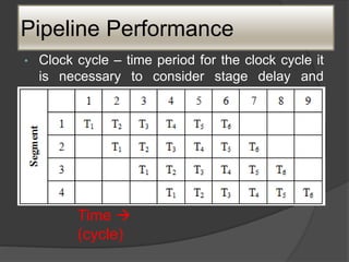
![Pipeline Performance
Total time required is, Tm = [m + (n-1)]t
Speedup factor: non-pipelined processor is
defined as,
Sm = (nm / m +(n-1) )
Where, n = segment/stages
M = no. of ins](https://image.slidesharecdn.com/caunitiii-230802092851-d22cc511/85/CA-UNIT-III-pptx-29-320.jpg)


![Side Effects
• When destination register of the current instruction
is the source register of the next instruction there is
a data dependency. It is explicit and it is identified
by register name.
• The addition of these 2 numbers may be
accomplished as follows:
ADD R1,R3
ADD with carry R2, R4
R2<- [R2]+[R4]+Carry](https://image.slidesharecdn.com/caunitiii-230802092851-d22cc511/85/CA-UNIT-III-pptx-43-320.jpg)