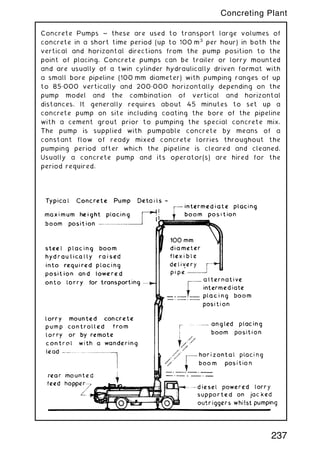
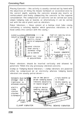
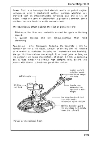
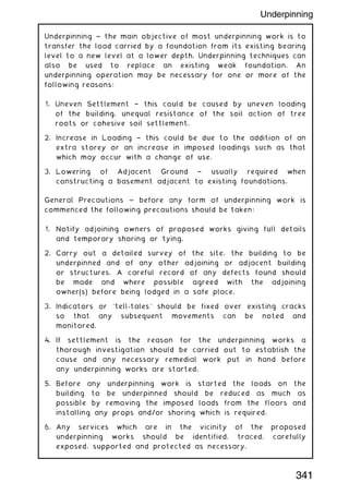
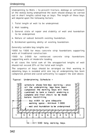
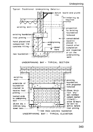
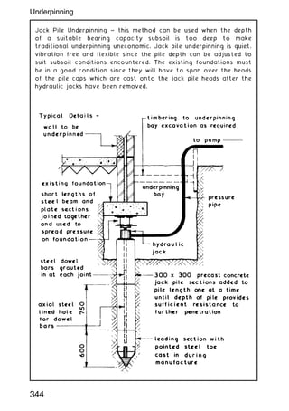
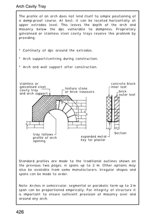
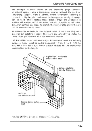
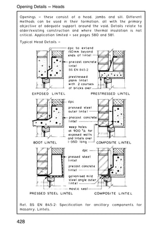
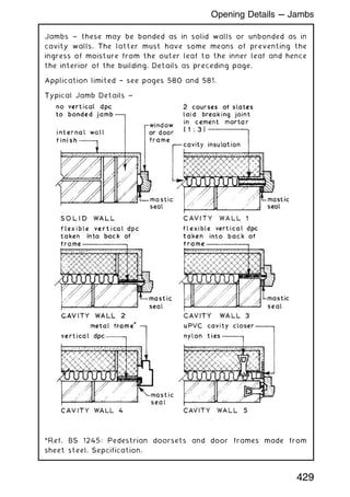
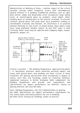
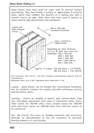
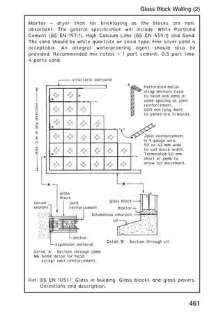
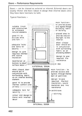
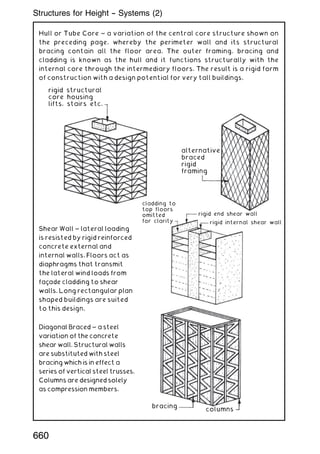
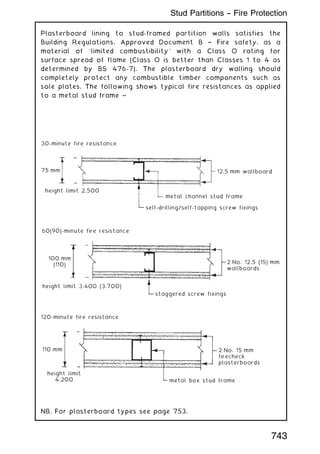
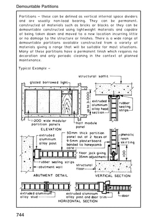
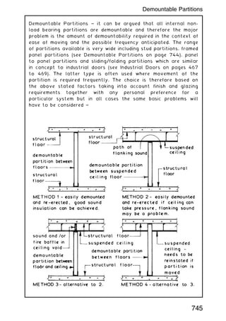
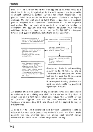
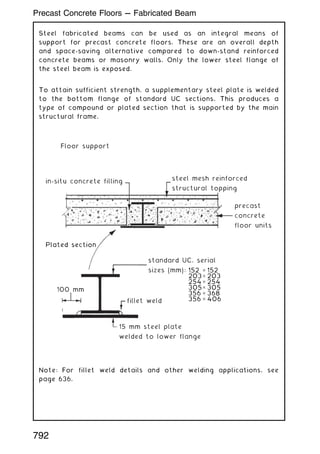
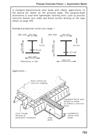
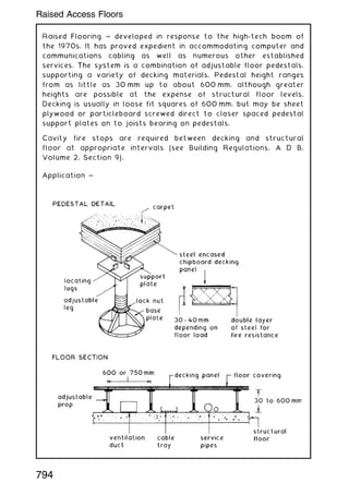
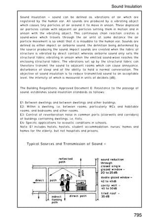
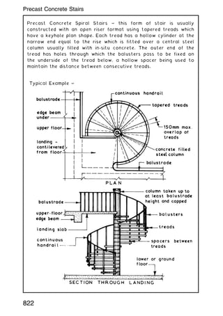
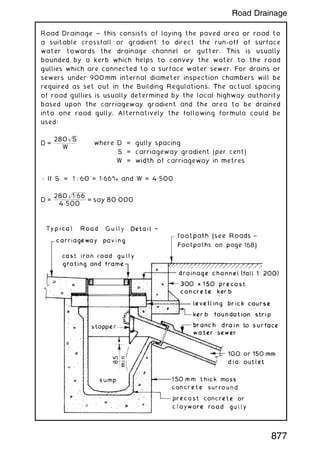
Downloaded 353 times
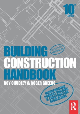


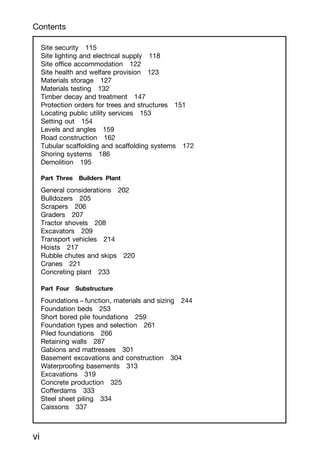


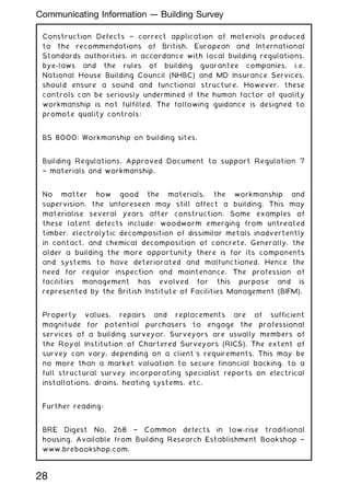
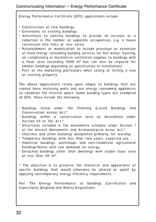


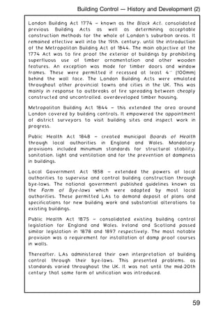
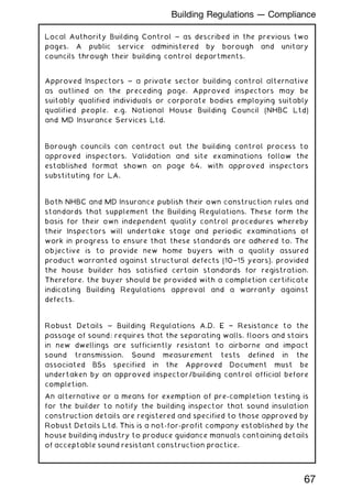


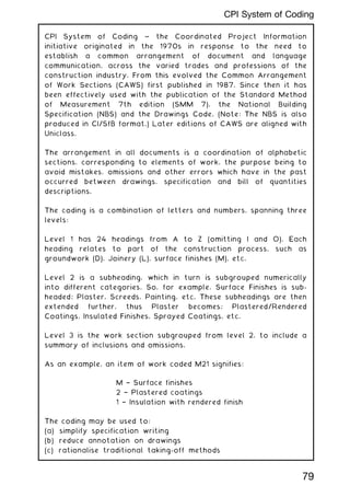
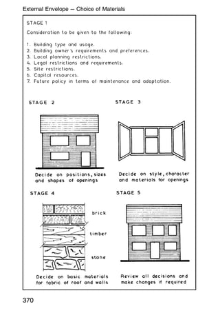
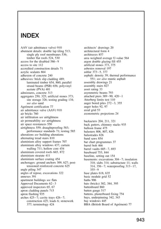
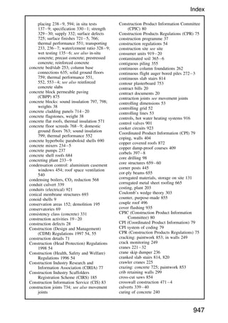
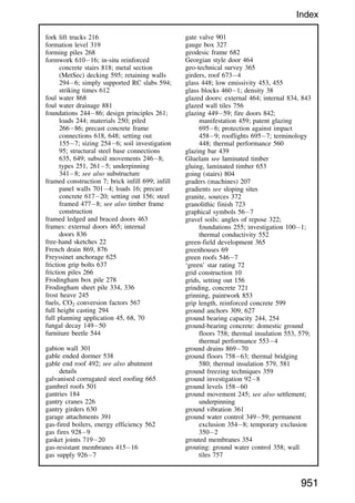
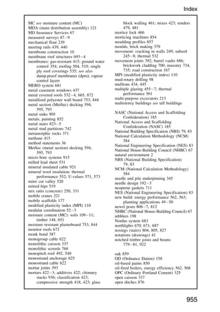
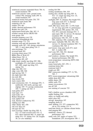
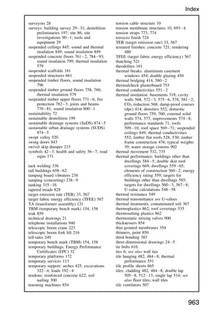
![Uniclass ~ the Unified Classification for the Construction Industry
was created in the 1990s by the Construction Project Information
Committee (CPIC) [see below] and first published by the RIBA in
1997.
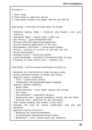
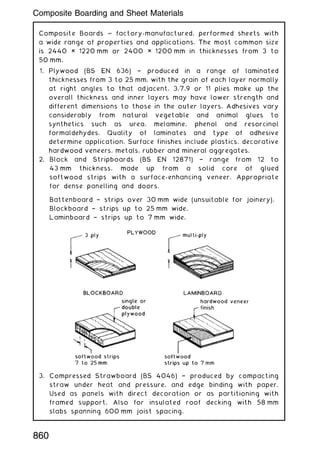
Purpose ~ to organise product literature and project information
into a structured library format. It incorporates the Common
Arrangement of Work Sections (CAWS) and the Electronic Product
Information Cooperation (EPIC) system of structuring product
literature and information.
Composition ~ comprises 15 tables (coded A to Q, I and O omitted),
each table an independent classification of specific information that
can be used solely or in combination with other table references
where subject matter is complex or diverse.
EPIC ~ an established European coding system for technical
product literature and information. Widely used across continental
Europe but less so in the UK. Favoured by some product
manufacturers in their presentation of data to architects and
engineers.
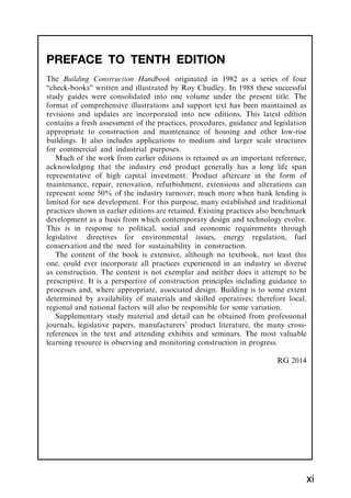
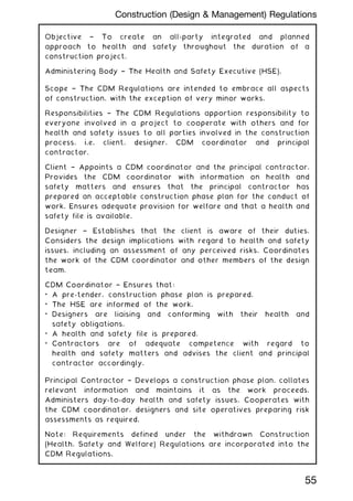
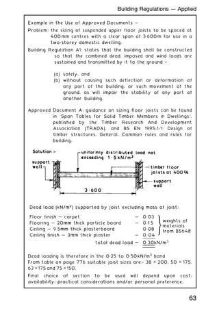
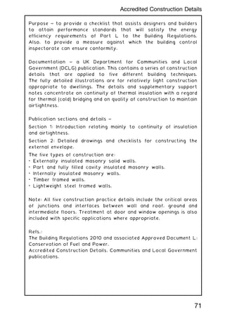
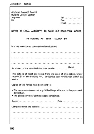
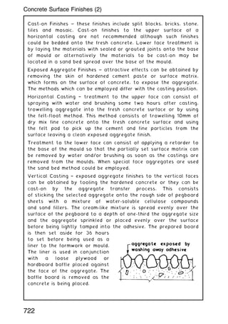
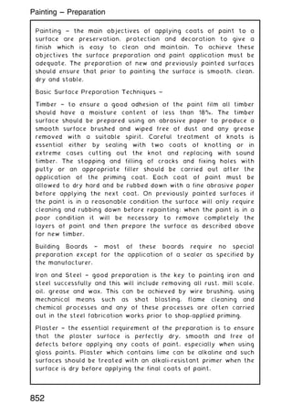
Product literature label showing CI/SfB, Uniclass and EPIC notation ~
CPIC members ~
Construction Confederation (CC).
Royal Institute of British Architects (RIBA).
Chartered Institute of Architectural Technologists (CIAT).
Chartered Institution of Building Services Engineers (CIBSE).
Royal Institution of Chartered Surveyors (RICS).
Institution of Civil Engineers (ICE).
(47)
CI/SfB
Uniclass
L5214
Ne5
EPIC
E312
80
Uniclass System of Coding](https://image.slidesharecdn.com/buildingconstructionhandbook-230110162241-051f4766/85/BUILDING-CONSTRUCTION-HANDBOOK-Tenth-edition-93-320.jpg)
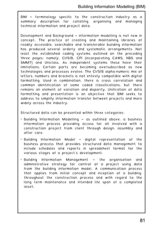

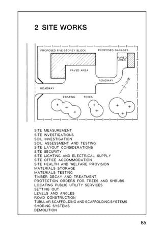
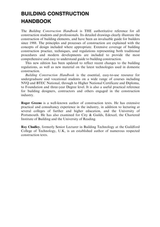
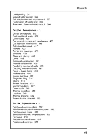
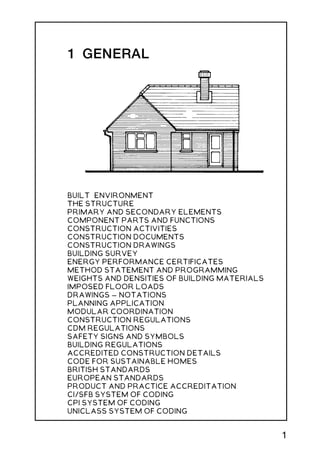
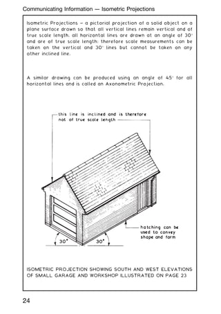
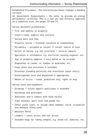
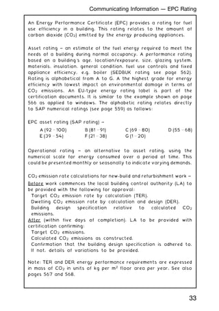
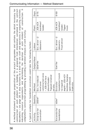
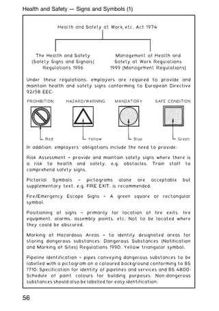
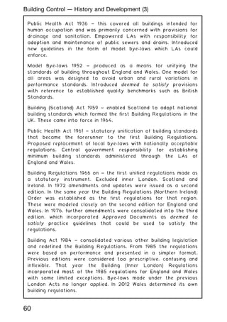
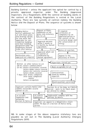
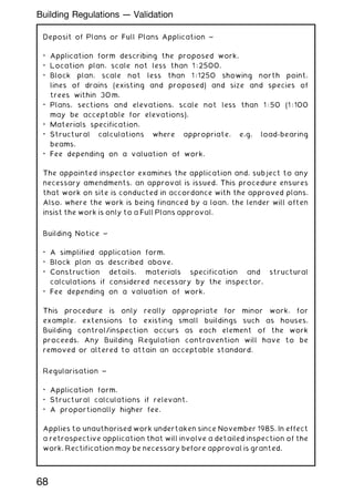
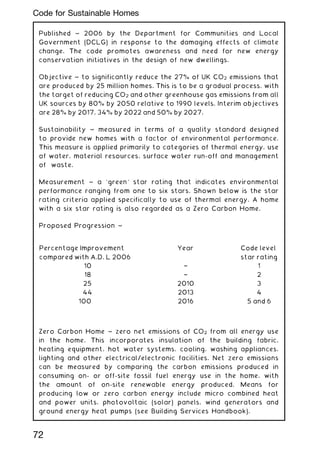
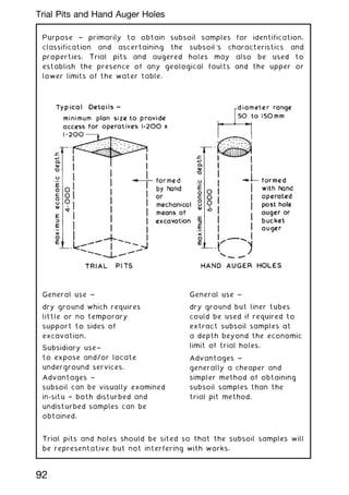
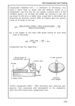
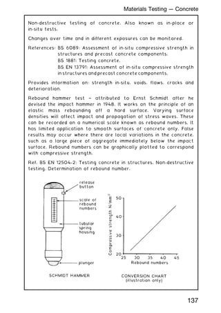
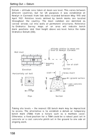
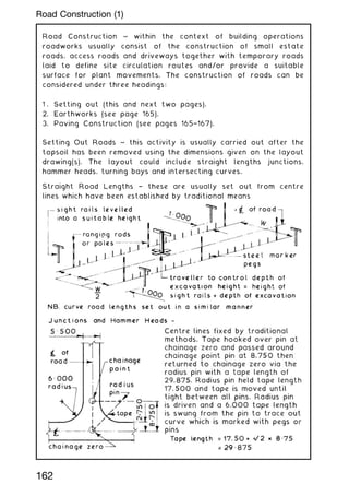
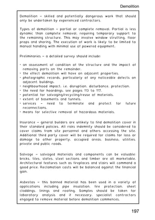
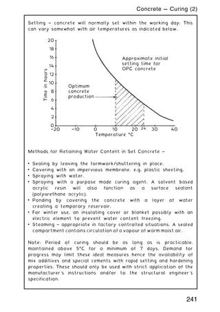
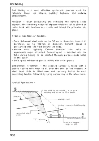
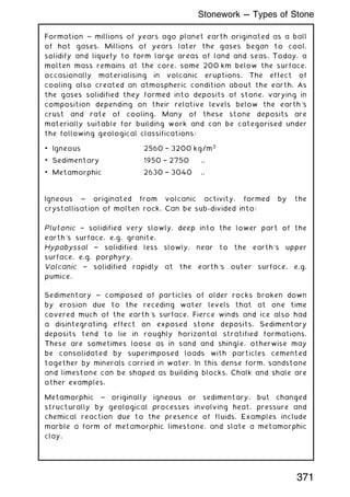
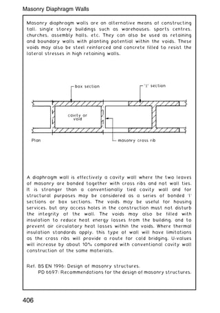
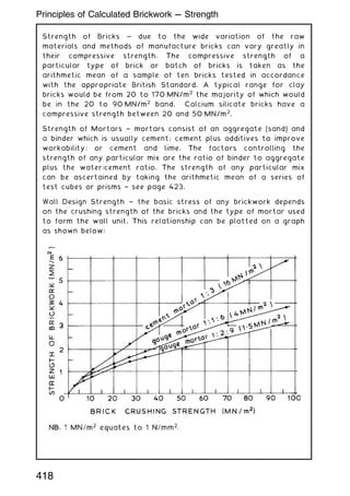
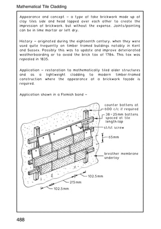
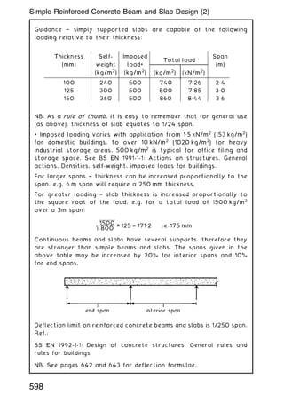
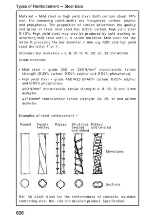
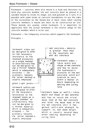
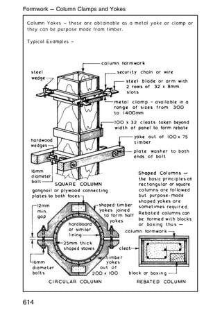
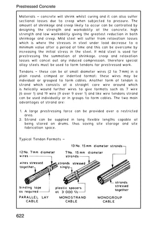
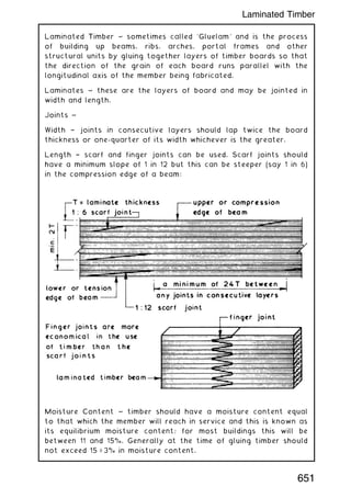
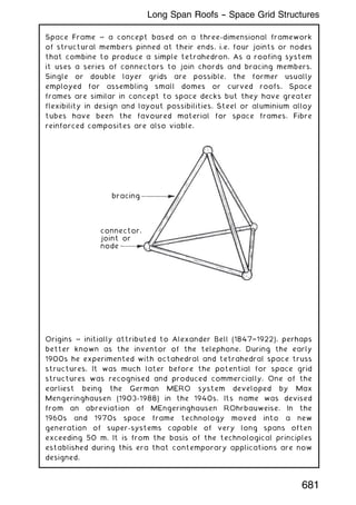
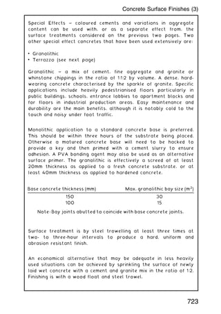
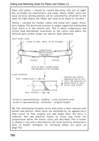
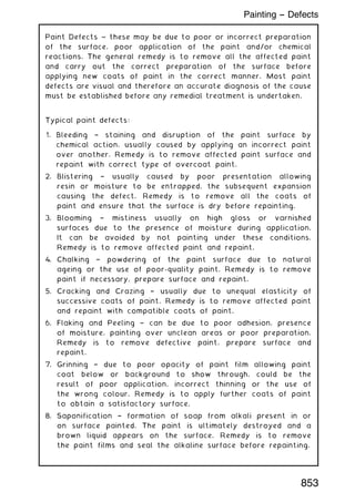
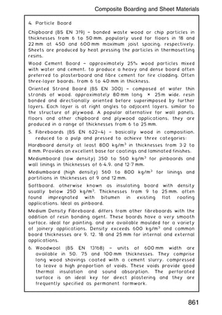
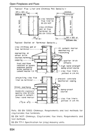
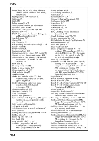
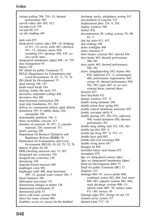
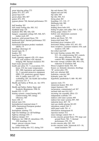
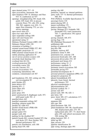
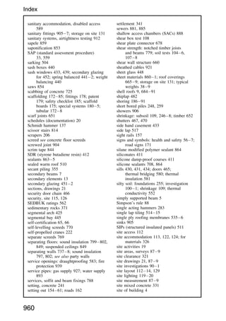
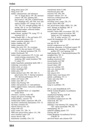
![Thomas Simpson (1710†1761) ~ a British mathematician who derived
interpolation and numerical methods of integration for calculation
of areas under curves.
Simpson's rule ~
A = w [(h1 + h7) + 4(h2 + h4 + h6) + 2(h3 + h5)] ÷ 3
Where: A = estimate of site area (m2
)
w = width or equal distances between ordinates (m)
h = height or length of parallel ordinates (m)
Note: requires an odd number of ordinates and an even number of
areas.
E.g.
parallel
ordinates
site boundary
h7
h6
h5
h4
h3
h2
w w w w w w
h1
If, h1 = 40 m, h2 = 36 m, h3 = 34 m, h4 = 34 m, h5 = 38 m, h6 = 36 m,
and h7 = 20 m. w = 12 m.
A = 12 [(40 + 20) + 4(36 + 36 + 36) + 2(34 + 38)] ÷ 3
A = 12 [60 + 432 + 144] ÷ 3
A = 12 ✕ 636 ÷ 3
A = 2544 m2
Note: An area 100 m ✕ 100 m (10,000 m2
) = 1 hectare (1 ha).
In the above calculation, 2544 m2
= 0.2544 ha.
In imperial measurement there are approximately 2.5 (2.471) acres
to 1 ha. Therefore 0.2544 ha = 0.6286 acres.
88
Site Measurement --- Simpson's Rule](https://image.slidesharecdn.com/buildingconstructionhandbook-230110162241-051f4766/85/BUILDING-CONSTRUCTION-HANDBOOK-Tenth-edition-101-320.jpg)
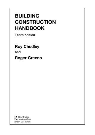
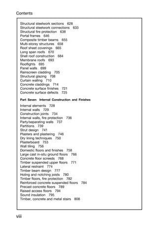
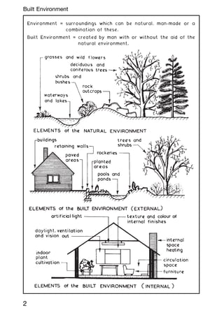
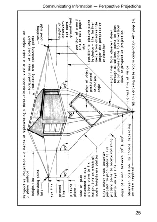
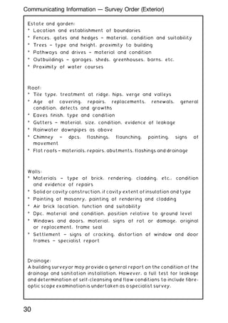
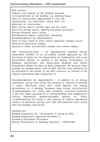
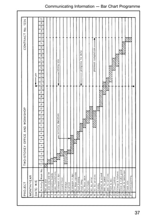
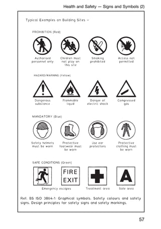
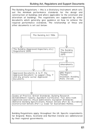
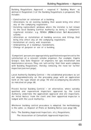
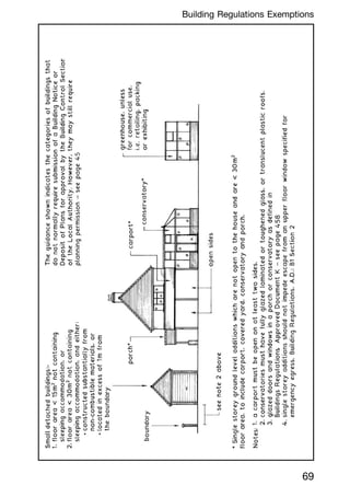
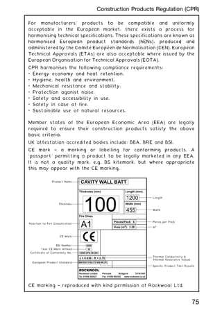
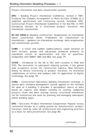
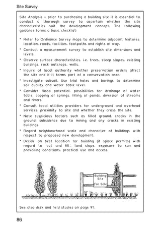
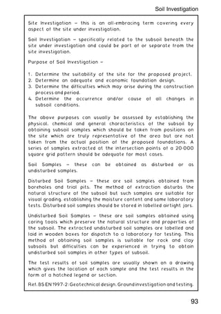
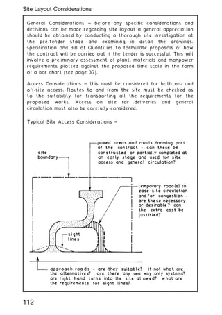
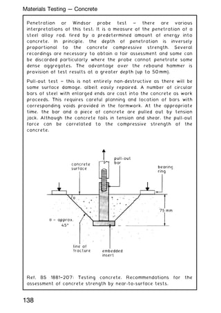
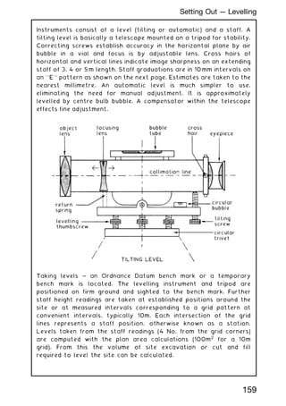
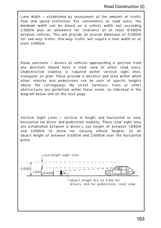
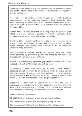
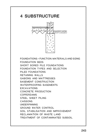
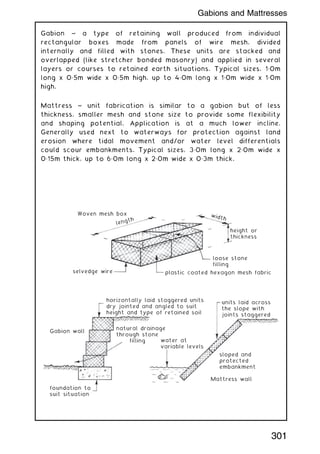
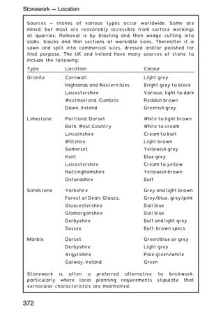
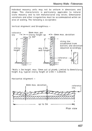
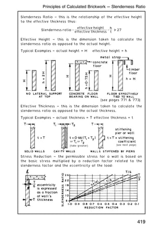
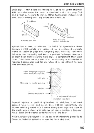
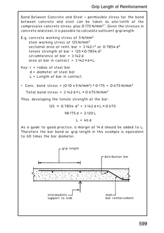
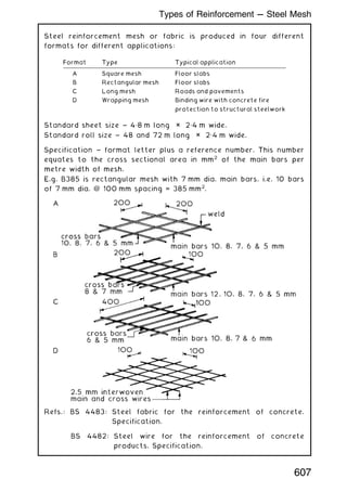
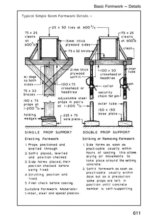
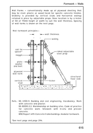
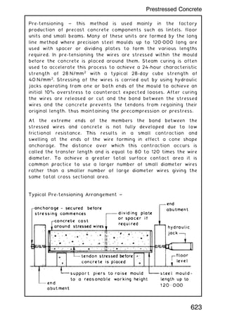
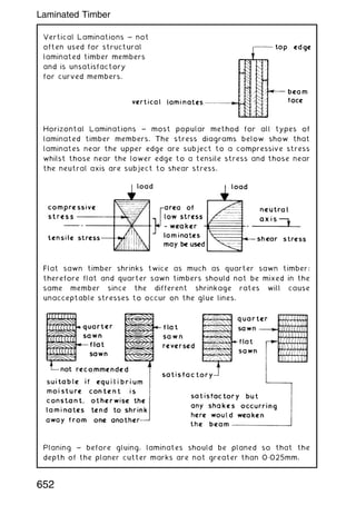
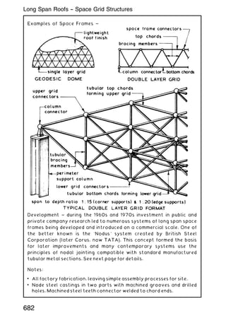
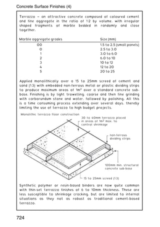
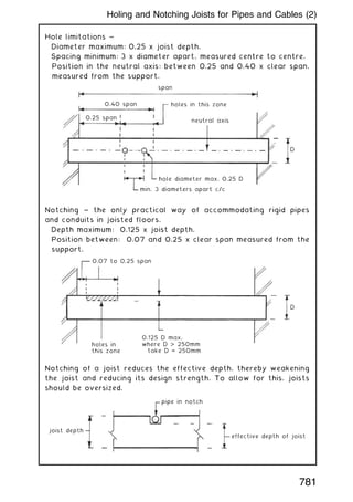
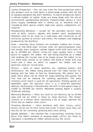
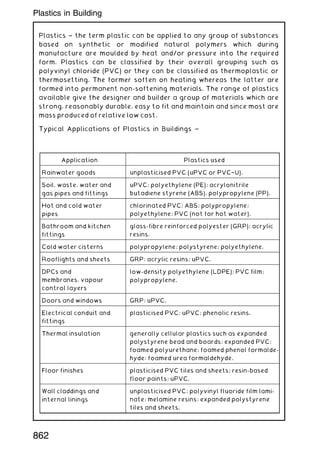
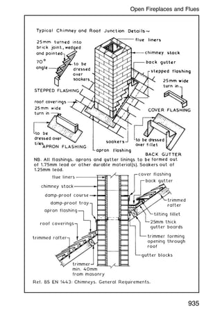
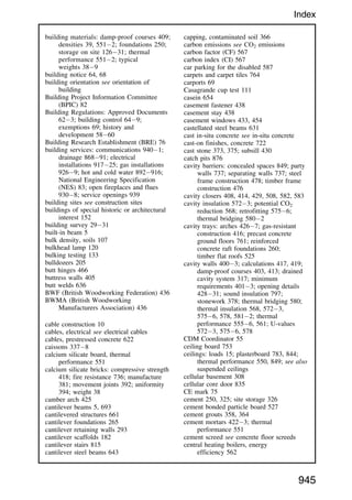
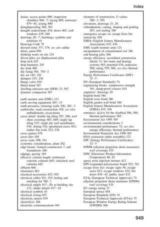
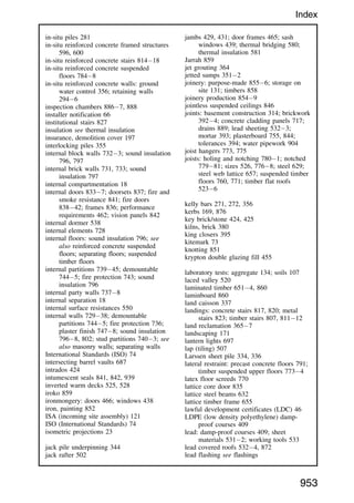
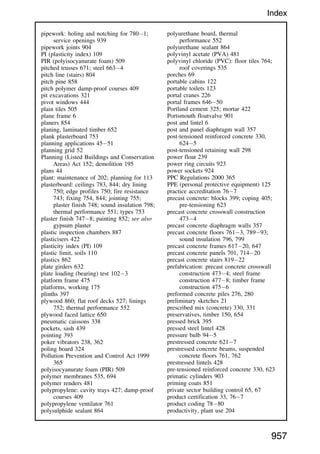
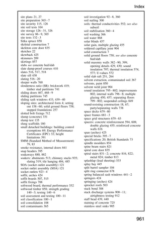
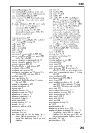
![Method ~ a little less accurate than Simpson's rule as it does not
assume a curved boundary, but it is adequate in most situations for
providing a reasonable estimate of site area. As with Simpson's
rule, the site plan area is divided into several parallel strips of
equal width (w).
E.g.
parallel
ordinates
site boundary
trapezoid
G
F
E
D
C
B
A
h7
h6
h5
h4
h3
h2
w w w w w w
h1
H J K L M N P
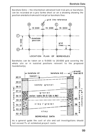
Area of trapezoid ABHJ = [(h1 + h2) ÷ 2] ✕ w
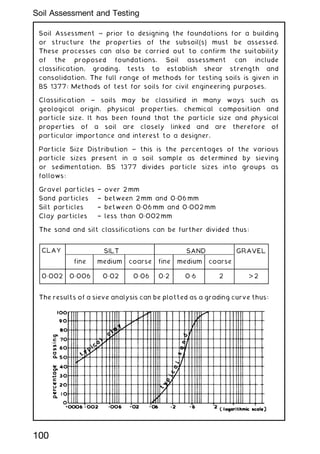
Area of trapezoid BCJK = [(h2 + h3) ÷ 2] ✕ w
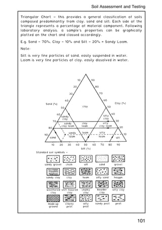
and so on until:
Area of trapezoid FGNP = [(h6 + h7) ÷ 2] ✕ w
Therefore the total plot area (A) will be the sum of the trapezoids
expressed as:
A = w {[(h1 + h7) ÷ 2] + h2 + h3 + h4 + h5 + h6}
E.g. Using the site dimensions from the previous page:
A = 12 {[(40 + 20) ÷ 2] + 36 + 34 + 36 + 38 + 36}
A = 12 {30 + 36 + 34 + 36 + 38 + 36}
A = 12 ✕ 210
A = 2520 m2
A fair comparison with the same area calculation of 2544 m2
using
Simpson's rule on the previous page. Greater accuracy can be
achieved by reducing the ordinate widths (w).
89
Site Measurement --- Trapezoidal Rule](https://image.slidesharecdn.com/buildingconstructionhandbook-230110162241-051f4766/85/BUILDING-CONSTRUCTION-HANDBOOK-Tenth-edition-102-320.jpg)
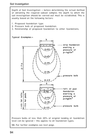
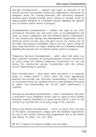
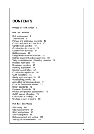
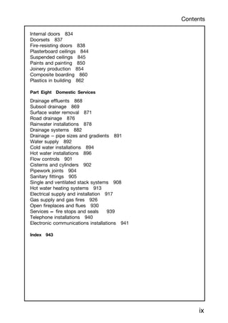
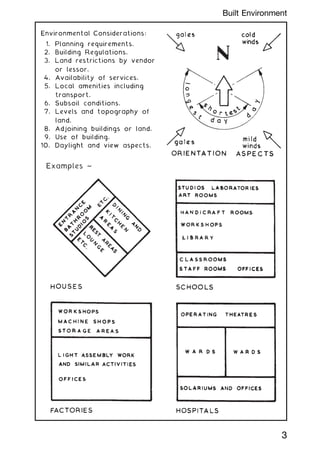
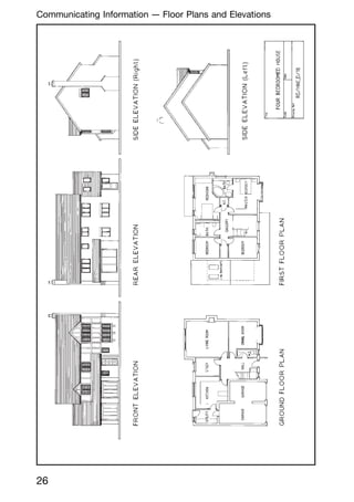
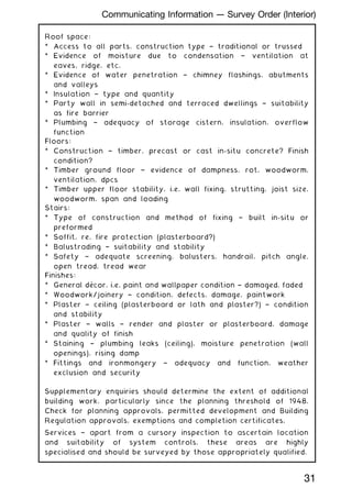
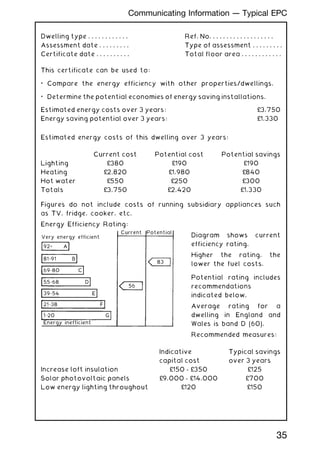
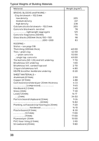
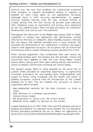
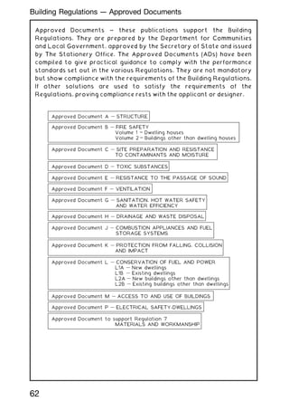
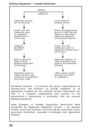
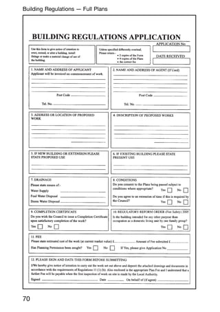
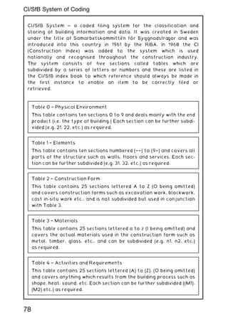
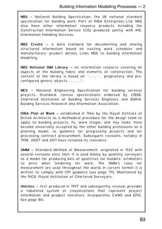
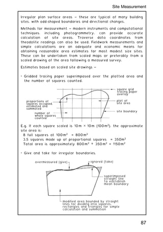
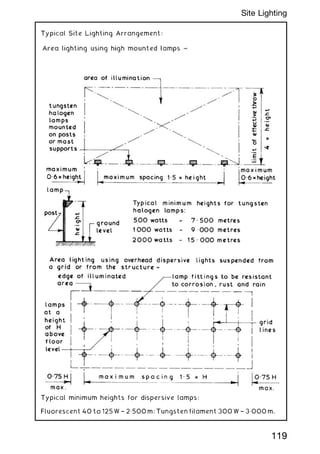
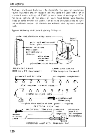
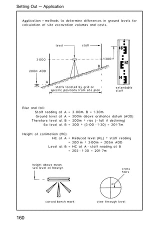
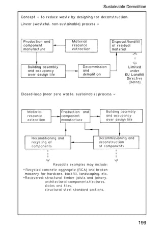
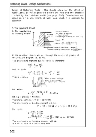
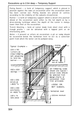
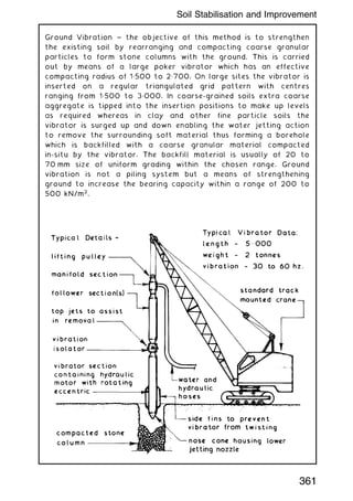
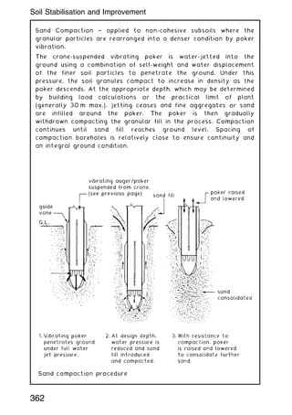
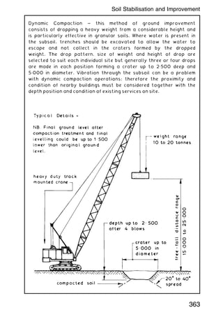
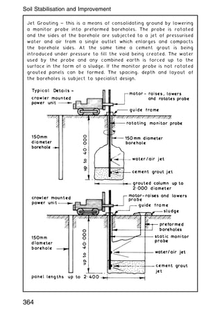
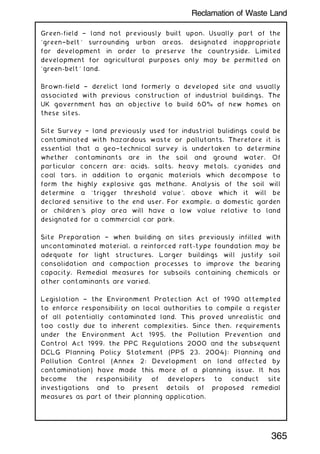
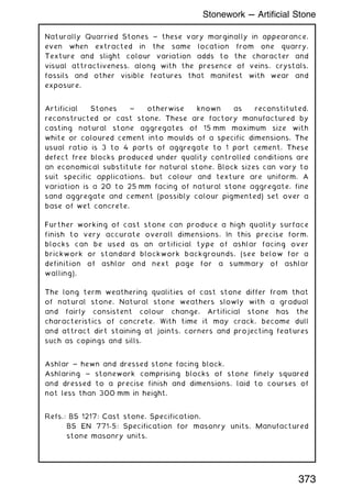
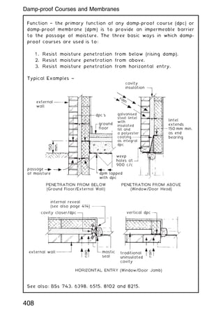
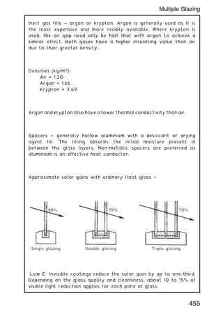
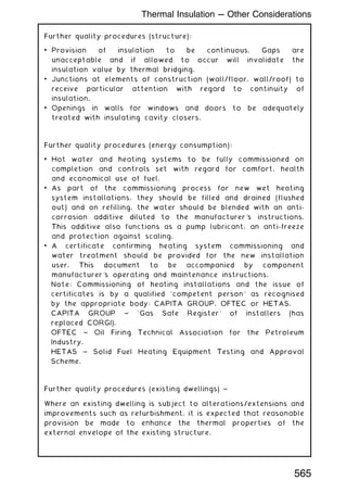
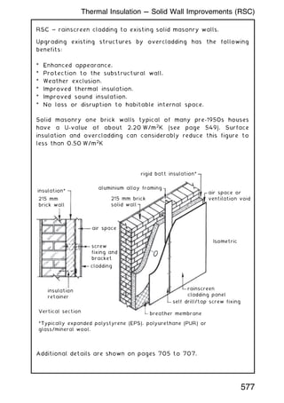
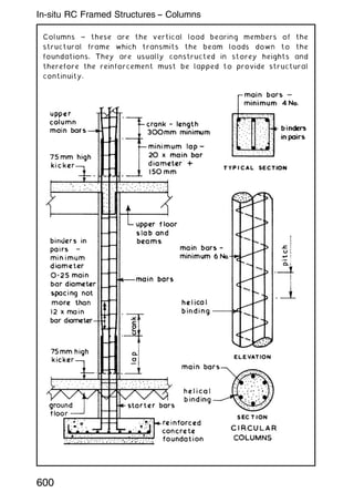
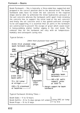
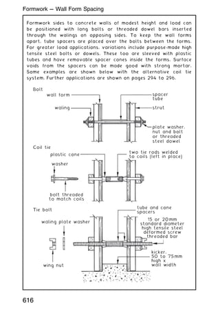
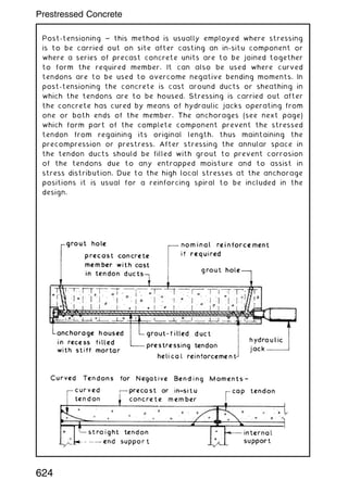
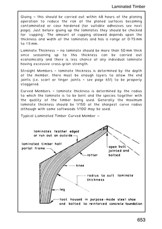
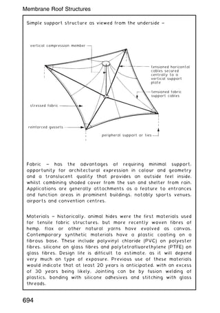
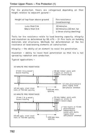
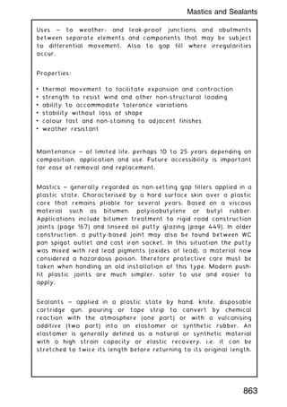
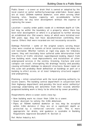
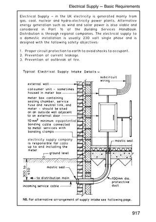
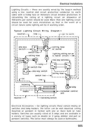
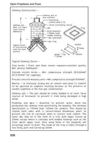
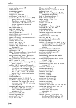
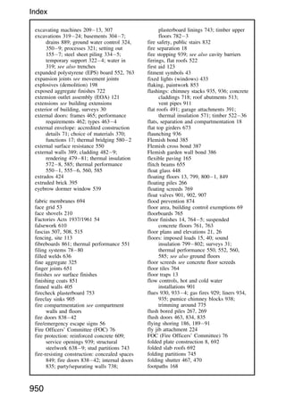
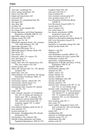
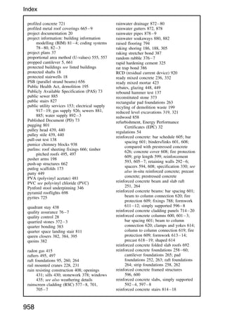
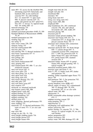
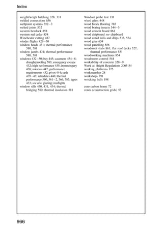
![Site Lighting ~ this can be used effectively to enable work to continue
during periods of inadequate daylight. It can also be used as a deterrent
to would-be trespassers. Site lighting can be employed externally to
illuminate the storage and circulation areas and internally for general
movement and for specific work tasks. The types of lamp available
range from simple tungsten filament lamps to tungsten halogen and
discharge lamps. The arrangement of site lighting can be static where
the lamps are fixed to support poles or mounted on items of fixed plant
such as scaffolding and tower cranes. Alternatively the lamps can be
sited locally where the work is in progress by being mounted on
a movable support or handheld with a trailing lead. Whenever the
position of site lighting is such that it can be manhandled it should be run
on a reduced voltage of 110 V single phase as opposed to the mains
voltage of 230 V.
To plan an adequate system of site lighting the types of activity
must be defined and given an illumination target value which is
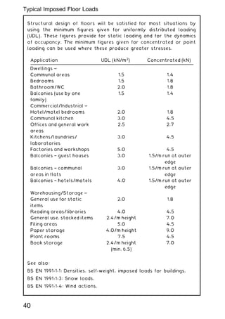
quoted in lux (lx). Recommended minimum target values for building
activities are:
Such target values do not take into account deterioration, dirt or
abnormal conditions; therefore it is usual to plan for at least twice
the recommended target values. Generally the manufacturers will
provide guidance as to the best arrangement to use in any
particular situation but lamp requirements can be calculated thus:
Total lumens
required
=
area to be illluminated (m
2
) ✕ t arg et value (lx)
utilisation factor 0„23 [dispersive lights 0„27]
After choosing lamp type to be used:
Number of
lamps required
=
total lumens required
lumen output of chosen lamp
118
Site Lighting](https://image.slidesharecdn.com/buildingconstructionhandbook-230110162241-051f4766/85/BUILDING-CONSTRUCTION-HANDBOOK-Tenth-edition-131-320.jpg)
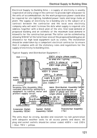
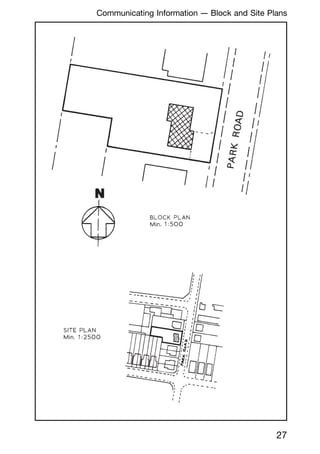
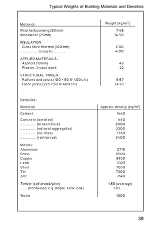
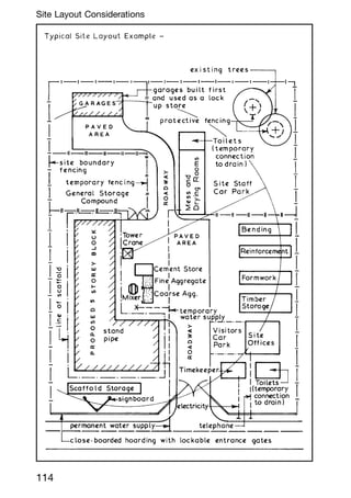
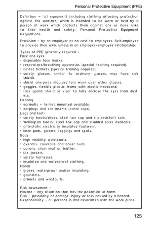
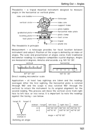
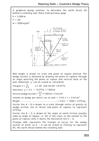
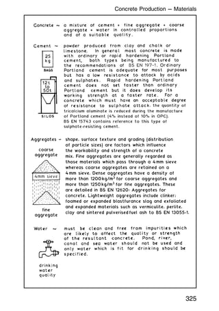
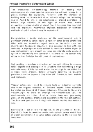
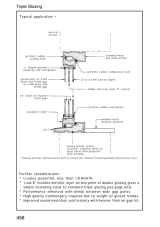
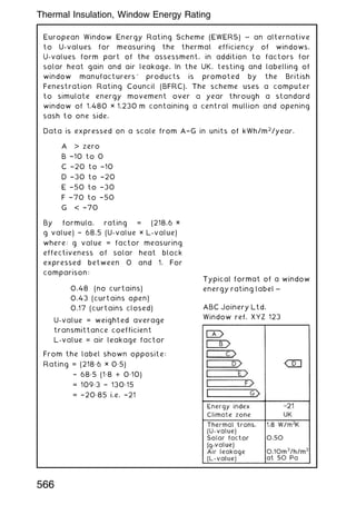
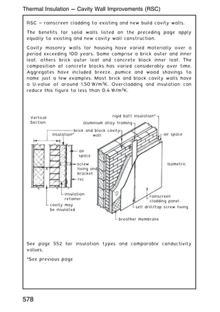
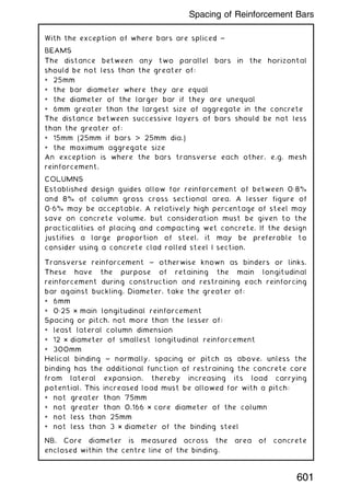
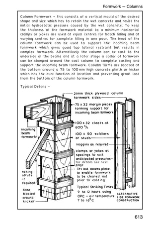
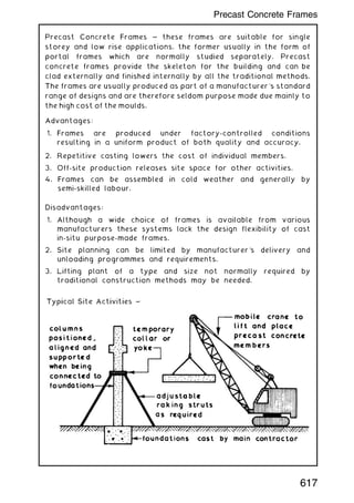
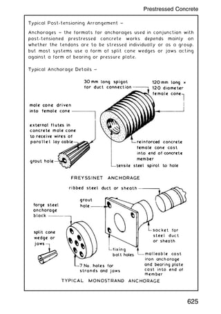
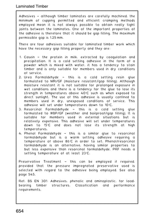
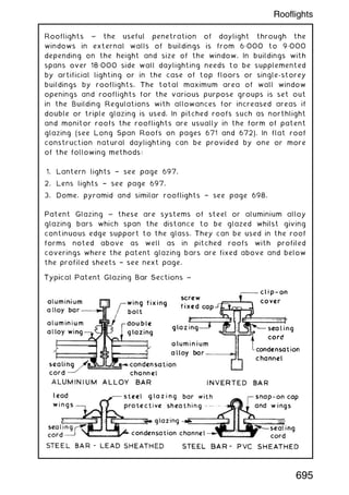
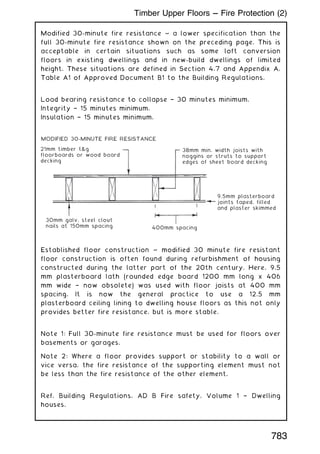
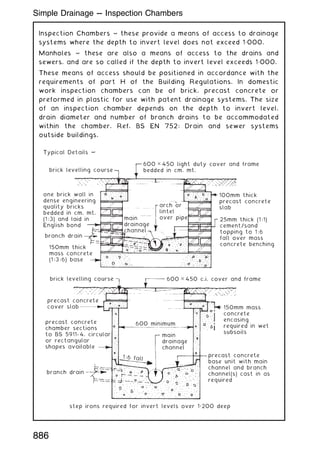
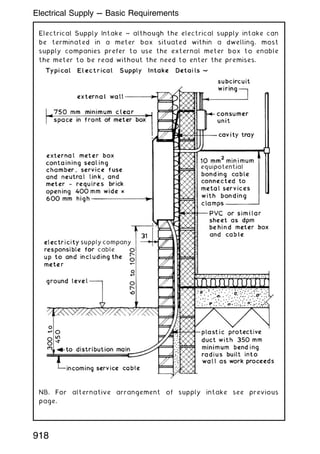
![Washing facilities:
• next to toilets and changing areas.
• hot and cold water or mixed warm water.
• soap, towels or hot air dryer.
• adequate ventilation and lighting.
• washbasins large enough to wash face, hands and forearms.
• showers for particularly dirty work.
Drinking water:
• wholesome supply direct from the mains.
• bottled water acceptable if mains supply unavailable.
• cups or other drinking vessels at outlets or a drinking fountain.
Accommodation for rest, shelter, changing and eating:
• separate provisions if men and women are on site.
• located close to washing facilities.
• heated place for shelter from inclement weather.
• space for changing with security for personal clothing, etc.
• lockers and/or place to hang clothes.
• place for wet clothing to be dried.
• rest facilities with tables and raised-back chairs.
• ventilation and lighting.
• means for heating water and warming food unless a separate
provision is made for providing meals.
Note: All facilities to be cleaned regularly and serviced with soap,
paper, towels, etc.
Refs.: Health and Safety at Work, etc. Act 1974.
Construction (Design and Management) Regulations 2007
[incorporating the Construction (Health, Safety and Welfare)
Regulations of 1996].
Health and Safety (First Aid) Regulations 1981.
Workplace (Health, Safety and Welfare) Regulations 1992.
Management of Health and Safety at Work Regulations 1999.
See also requirements and responsibilities for personal protective
equipment and clothing summarised on the next page.
124
Site Health and Welfare Provision (2)](https://image.slidesharecdn.com/buildingconstructionhandbook-230110162241-051f4766/85/BUILDING-CONSTRUCTION-HANDBOOK-Tenth-edition-137-320.jpg)
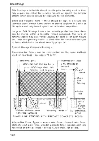
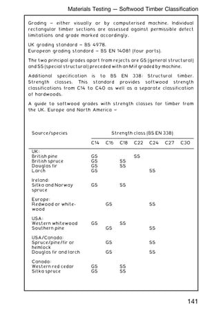
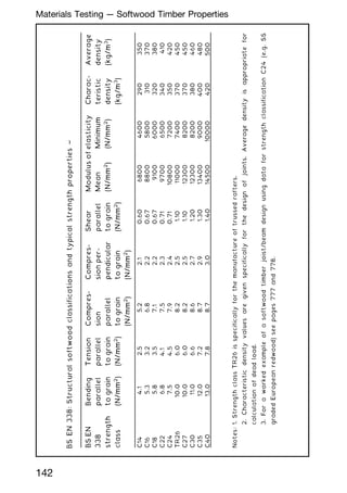
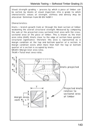
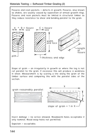
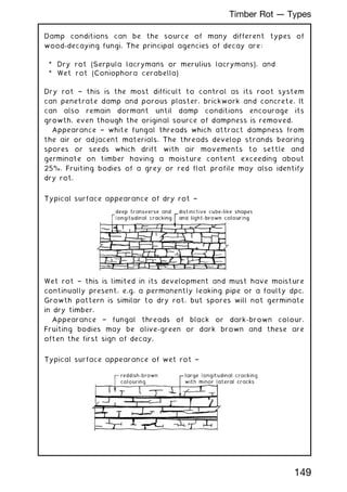
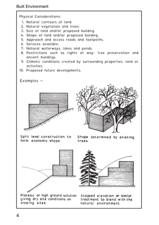
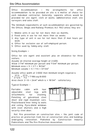
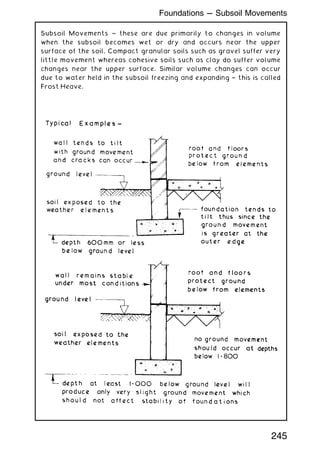
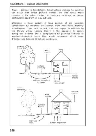
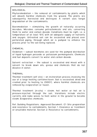
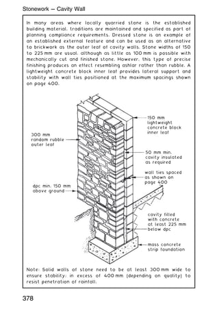
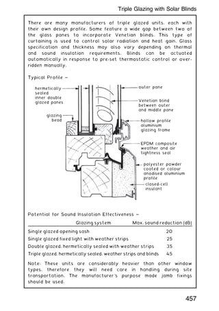
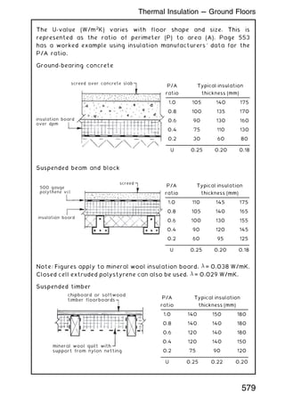
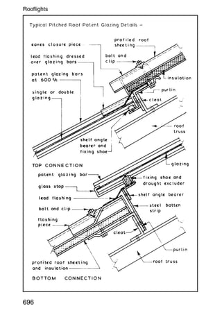
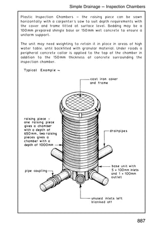
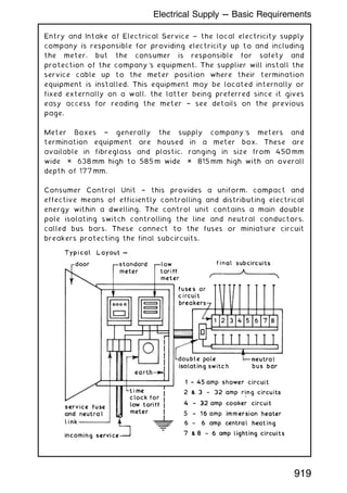
![Trees are part of our national heritage and are also the source of
timber. To maintain this source a control over tree felling has been
established under the Forestry Act which places the control
responsibility on the Forestry Commission. Local planning authorities
also have powers under the Town and Country Planning Act and the
Town and Country Amenities Act to protect trees by making tree
preservation orders. A TPO may be applied if the LPA consider that it
is ``expedient in the interests of amenity to make provision for the
preservation of trees or woodlands in their area'' (Section 198[1] of
the Town and Country Planning Act). Before cutting down, uprooting,
severing roots, topping off, lopping, damaging or destroying a tree, a
formal application must be submitted to the LPA for consent.
Contravention of such an order can lead to a substantial fine and a
compulsion to replace any protected tree which has been removed
or destroyed. Trees on building sites which are covered by a tree
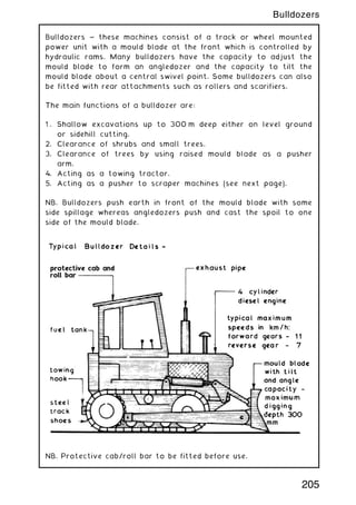
preservation order should be protected by a suitable fence.
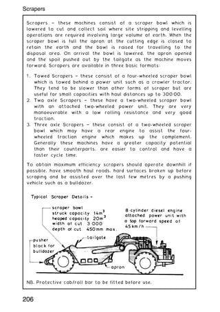
Definition and interpretation of what constitutes a tree (e.g. trunk
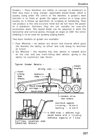
diameter, overall height, etc.) will vary and may be considered
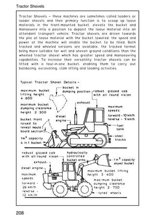
subjective. Therefore, appeals will be considered. If upheld, an
agreement for replacement trees is usual, in at least the same
quantity of the same species within the proposed development site.
Trees, shrubs, bushes and tree roots which are to be removed from
site can usually be grubbed out using handheld tools such as saws,
picks and spades. Where whole trees are to be removed for
relocation special labour and equipment is required to ensure that
the roots, root earth ball and bark are not damaged.
Ref. BS 5837: Trees in relation to design, demolition and
construction, Recommendations.
151
Protection Orders for Trees](https://image.slidesharecdn.com/buildingconstructionhandbook-230110162241-051f4766/85/BUILDING-CONSTRUCTION-HANDBOOK-Tenth-edition-164-320.jpg)
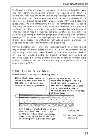
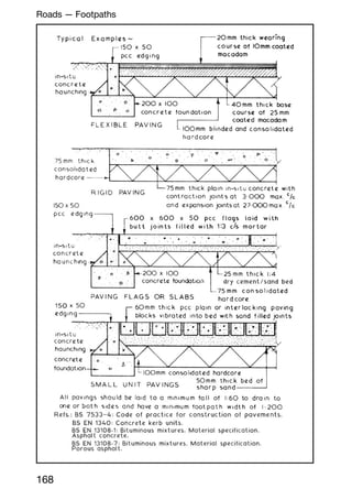
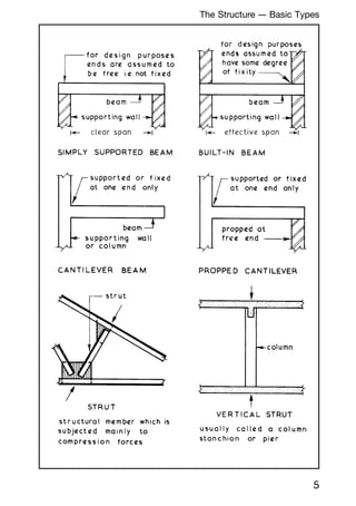
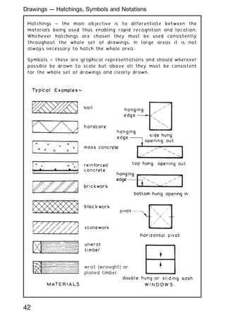
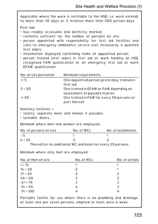
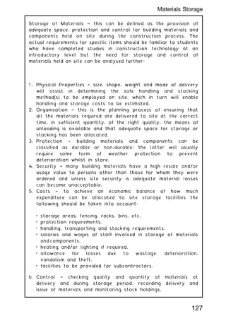
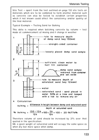
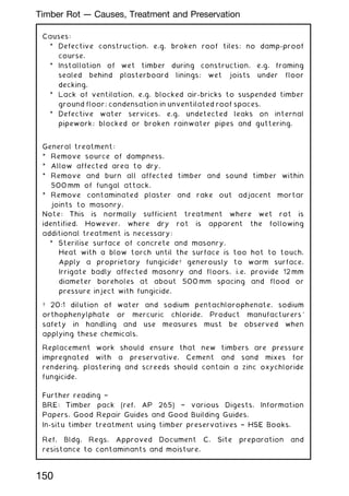
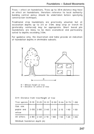
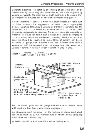
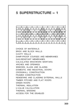
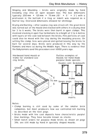
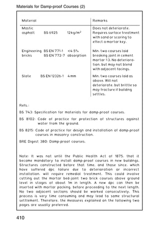
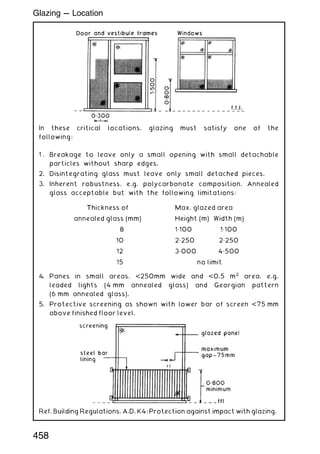
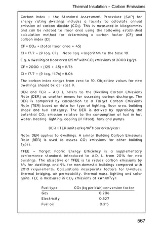
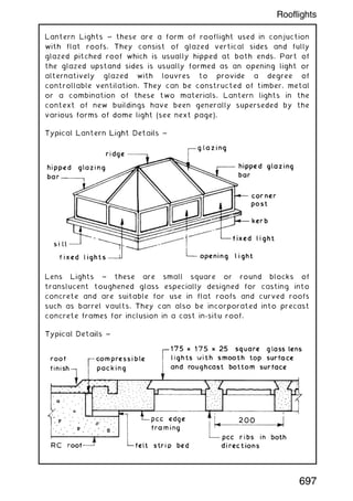
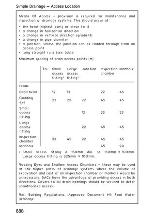
![Concrete paving flags † BS dimensions:
Note: All dimensions in millimetres.
Tactile flags † manufactured with a blistered (shown) or ribbed
surface. Used in walkways to provide warning of hazards or to
enable recognition of locations for people whose visibility is
impaired. See also Department of Transport Disability Circular DU
1/86[1], for uses and applications.
Ref. BS EN 1339: Concrete paving flags. Requirements and test
methods.
Type Size (nominal) Size (work) Thickness (T)
A † plain 600 ✕ 450 598 ✕ 448 50 or 63
B † plain 600 ✕ 600 598 ✕ 598 50 or 63
C † plain 600 ✕ 750 598 ✕ 748 50 or 63
D † plain 600 ✕ 900 598 ✕ 898 50 or 63
E † plain 450 ✕ 450 448✕ 448 50 or 70
TA/E † tactile 450 ✕ 450 448✕ 448 50 or 70
TA/F † tactile 400 ✕ 400 398 ✕ 398 50 or 65
TA/G † tactile 300 ✕ 300 298 ✕ 298 50 or 60
170
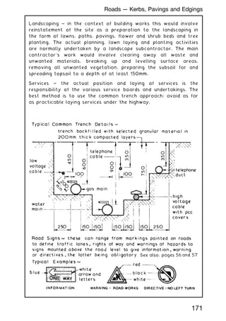
Roads --- Kerbs, Pavings and Edgings](https://image.slidesharecdn.com/buildingconstructionhandbook-230110162241-051f4766/85/BUILDING-CONSTRUCTION-HANDBOOK-Tenth-edition-183-320.jpg)
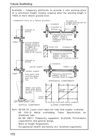
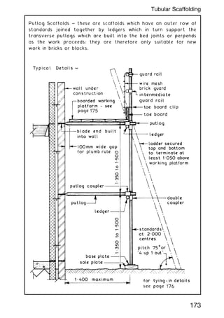
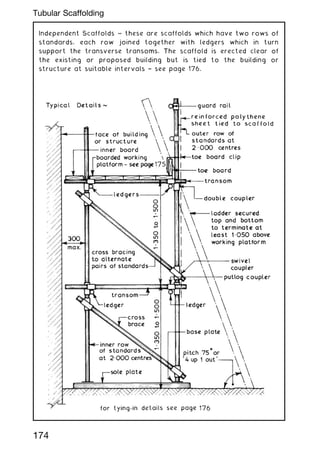
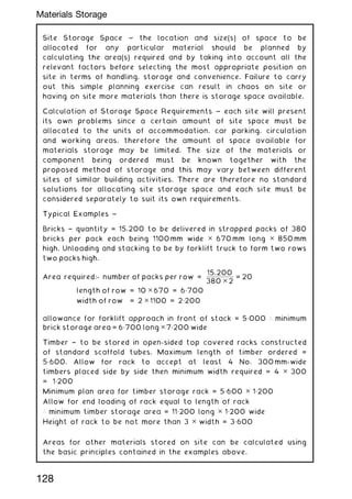
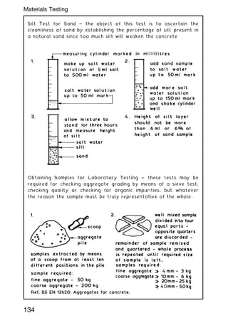
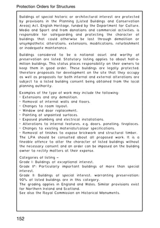
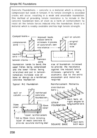
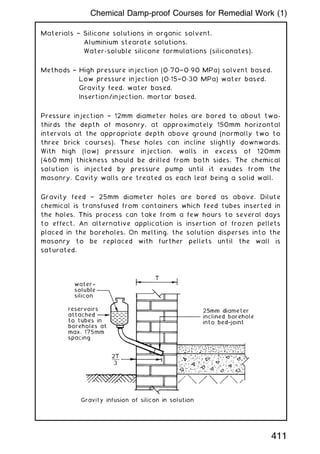
![Principle Considerations ~
• Structural stability and integrity.
• Safety of personnel using a scaffold and for those in the vicinity.
Relevant Factors ~
• Simple configurations of putlog and independent scaffold, otherwise
known as basic systems (see National Access and Scaffolding
Confederation [NASC] technical guidance) do not require specific design
calculations. Structural calculations are to be prepared by an
appropriately qualified person for other applications.
• Assembly, alterations and dismantling to be undertaken in
accordance with NASC technical guidance or system scaffolding
manufacturer's instructions.
• Scaffold erectors to be competence qualified, e.g. having
attended a Construction Industry Scaffolders Registration
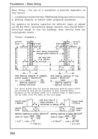
Scheme (CISRS) course and be in possession of a scaffolder's
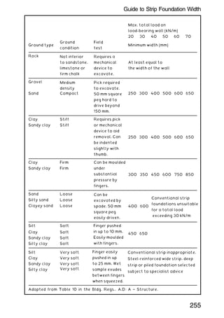
card. Trainees to be supervised by a competent qualified
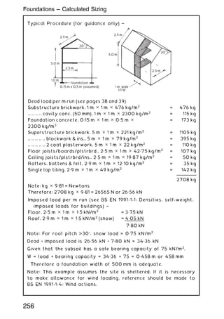
person, e.g. foreman scaffolder.
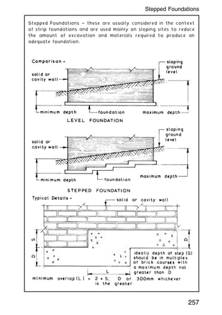
• Non-basic scaffolds should have a sequence and methodology for
assembly and dismantling, plus further guidance for any anticipated
alterations included with the design information. Any unforeseen
alterations should receive specific design consideration.
• On completion, the scaffold supplier should provide a `handover
certificate' endorsed with references to design drawings and
calculations. Any limitations of use, with particular mention of
platform safe working loads, to be documented.
• Completed scaffolds to be inspected by a competent person, i.e.
suitably qualified by experience and training. The latter assessed
by the CISRS or by certificated attendance on a system scaffold
manufacturer's course. This does not apply to basic systems
mentioned in the first bullet point. These can be approved by a
person of sufficient site experience such as a site manager.
• Inspection reports to be undertaken daily before work
commences, after adverse weather and when alterations,
modifications or additions are made. Any defects noted and
corrective action taken.
• Incomplete scaffolds should be suitably signed for non-access.
Physical barriers to be in place during assembly and dismantling.
• Inspection records to be documented and filed. These to include
location and description of the scaffold, time and date of
inspection, result of inspection and any actions taken. The
report to be authorised by signature and endorsed with the
inspector's job title.
185
Scaffolding Systems --- Safety Checklist](https://image.slidesharecdn.com/buildingconstructionhandbook-230110162241-051f4766/85/BUILDING-CONSTRUCTION-HANDBOOK-Tenth-edition-198-320.jpg)


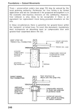
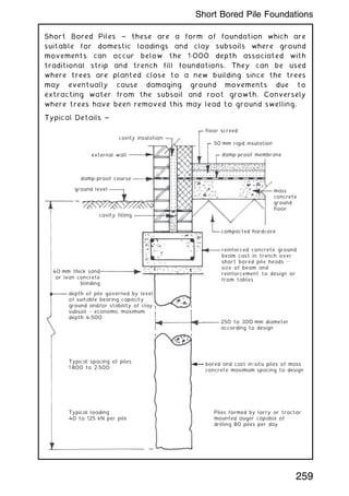
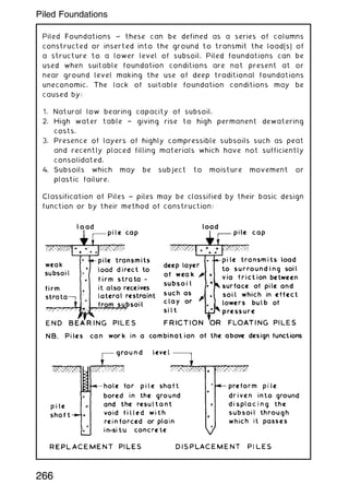

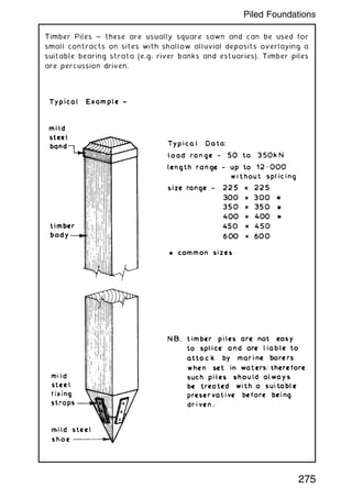
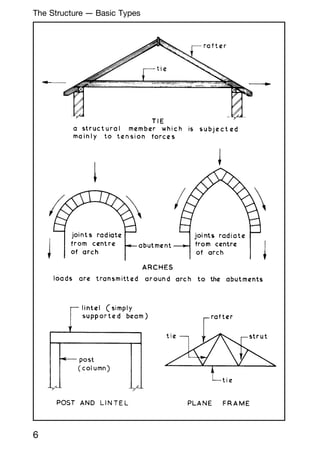
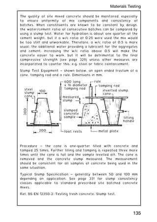
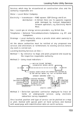
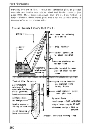
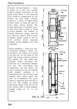
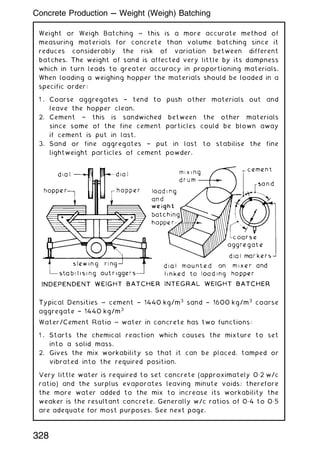
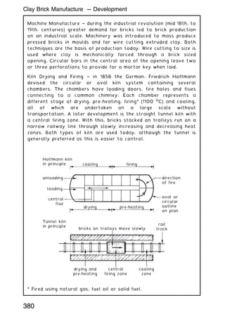
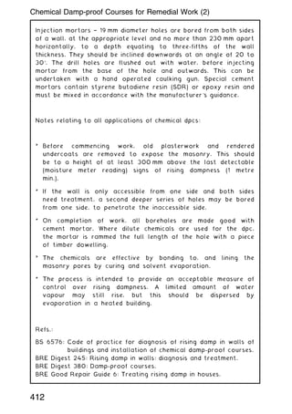
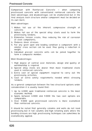
![Preformed Concrete Piles † jointing with a peripheral steel splicing
collar as shown on the preceding page is adequate for most
concentrically or directly loaded situations. Where very long piles
are to be used and/or high stresses due to compression, tension
and bending from the superstructure or the ground conditions are
anticipated, the four or eight lock pile joint [AARSLEFF PILING]
may be considered.
hardwood or dense plastic
driving plate removed
steel dowel with
void for pin
treated steel
shutter and pile
lock bonded to
pile reinforcement
*upper section as lower section but
inverted and dowels located over holes
lower preformed
concrete pile
section*
high tensile
steel locking pin
Pile dimensions (mm) Possible no. of locks per joint
250 ✕ 250, 300 ✕ 300,
350 ✕ 350 and 400 ✕ 400
4
350 ✕ 350, 400 ✕ 400
and 450 ✕ 450
8
277
Piled Foundations](https://image.slidesharecdn.com/buildingconstructionhandbook-230110162241-051f4766/85/BUILDING-CONSTRUCTION-HANDBOOK-Tenth-edition-290-320.jpg)
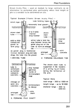
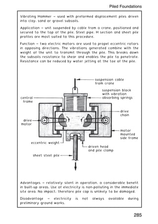
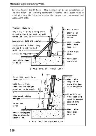
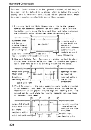
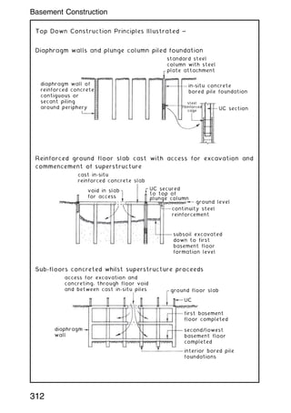
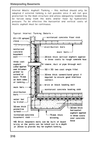

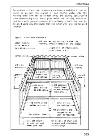
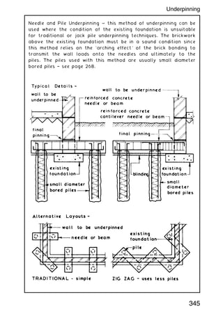

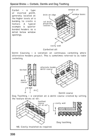
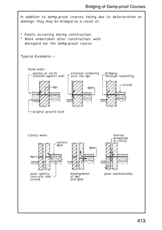
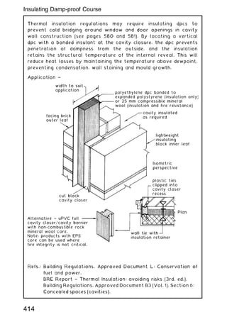
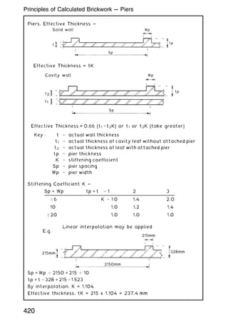
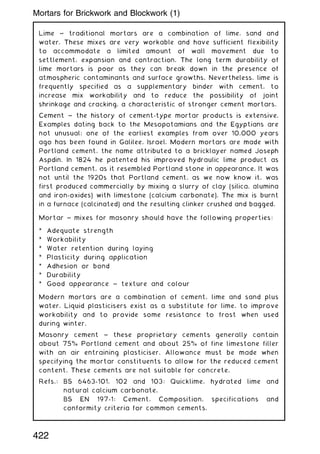

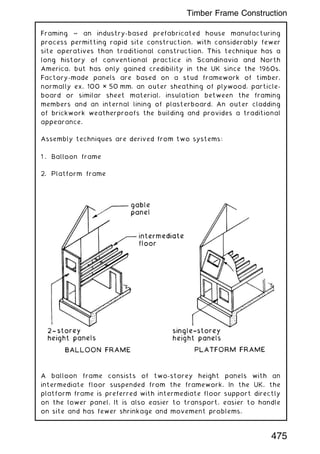
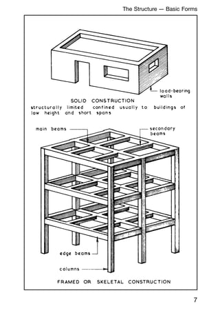
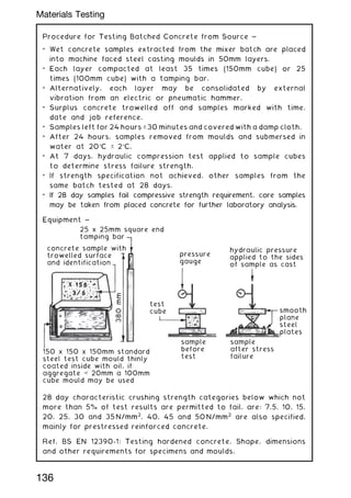
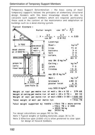
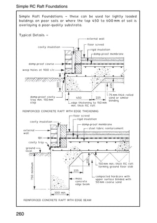
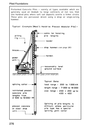
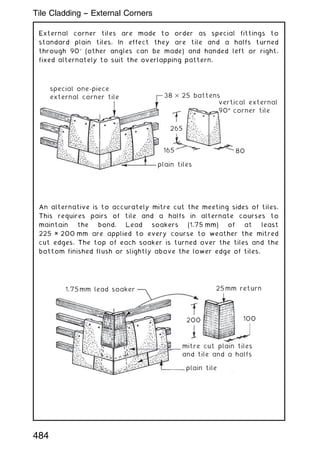
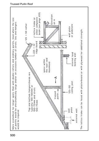
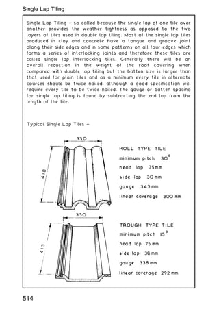
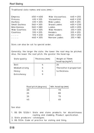
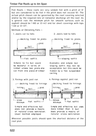
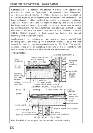
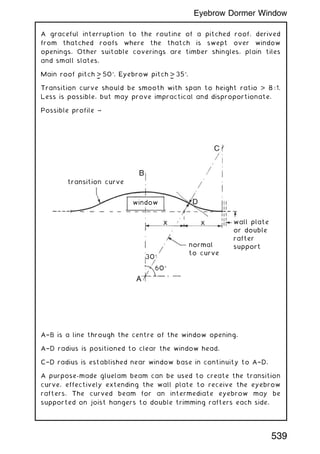
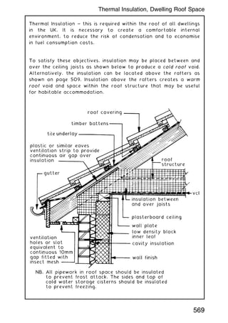
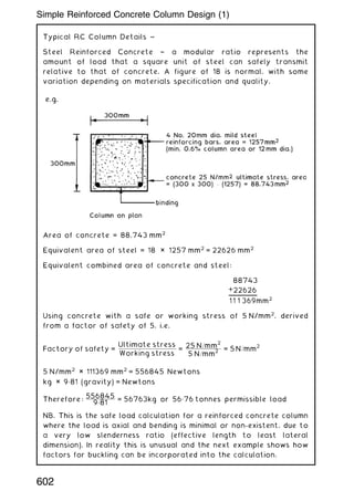
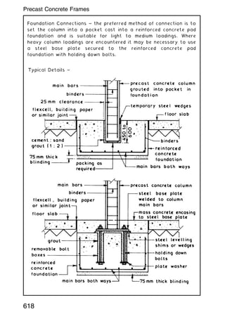
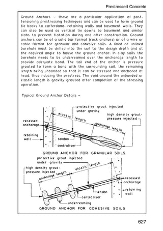
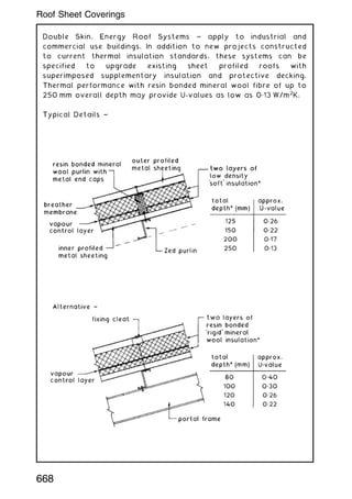
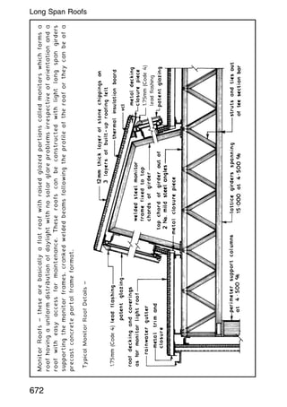
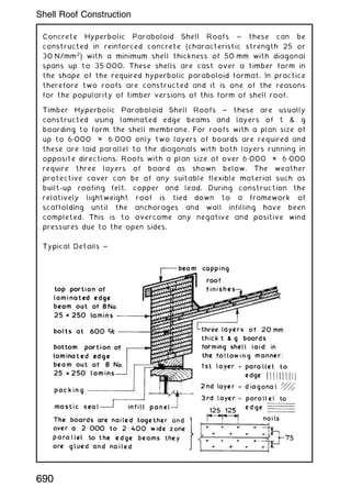
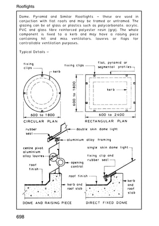
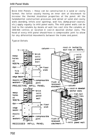
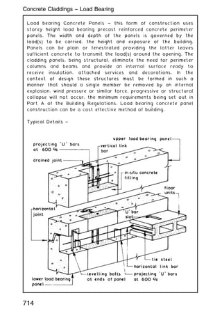
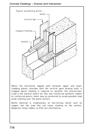
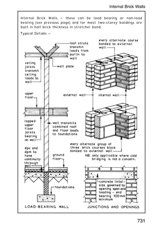
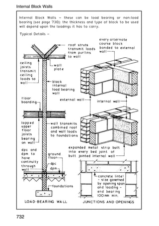
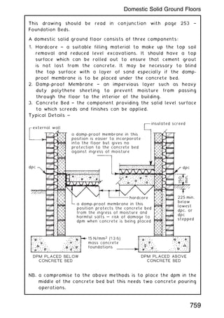
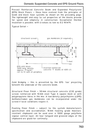
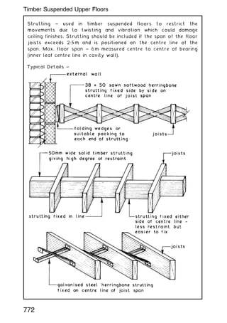
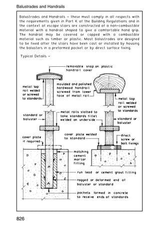
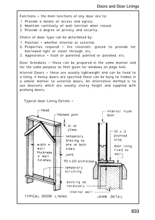
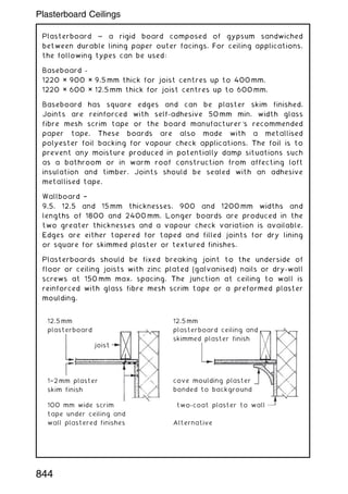
![Typical Details ~
Eaves
insulated cavity closer
barrier (see Building
Regs. A. D.: B3,
Section 6 [Vol. 1]
and 9 [Vol. 2]) and
plywood bracket
bolted channel
section truss
storey height
modular frame
brickwork
outer leaf
channel section
floor joists
ground
floor
slab
channel section
truss members
header binder or wall
plate
stud framing
fire-retardant insulation
breather membrane
wall tie
50mm
cavity
insulation between studding
and into cavity
Intermediate floor Ground floor
plaster-
board
plywood
deck
dpc
channel
section
floor
joists
insulated cavity
barrier/fire stop if
a compartment floor
concrete slab
or beam and
block floor
dpm
insulation
screed
anchor
bolt
12.5 mm vapour check
plasterboard screwed
to stud framework
Advantages:
• Factory made, therefore produced to quality controlled
standards and tolerances.
• Relatively simple to assemble on site † bolted connections in
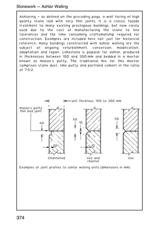
preformed holes.
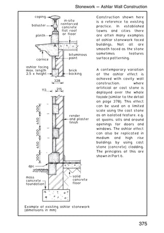
• Dimensionally stable, consistent composition, insignificant
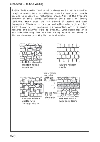
movement.
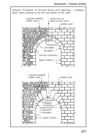
• Unaffected by moisture, therefore will not rot.
• Does not burn.
• Inedible by insects.
• Roof spans potentially long relative to weight.
Disadvantages:
• Possibility of corrosion if galvanised protective layer is
damaged.
• Deforms at high temperature, therefore unpredictable in fire.
• Electricity conductor † must be earthed.
478
Steel Frame Construction (2)](https://image.slidesharecdn.com/buildingconstructionhandbook-230110162241-051f4766/85/BUILDING-CONSTRUCTION-HANDBOOK-Tenth-edition-491-320.jpg)
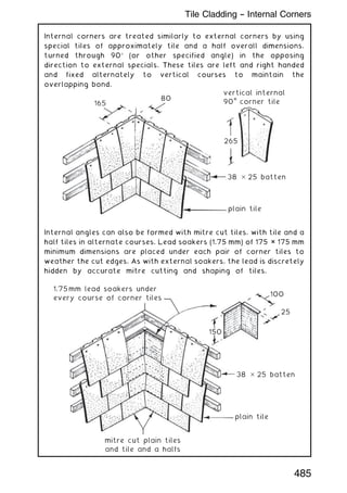
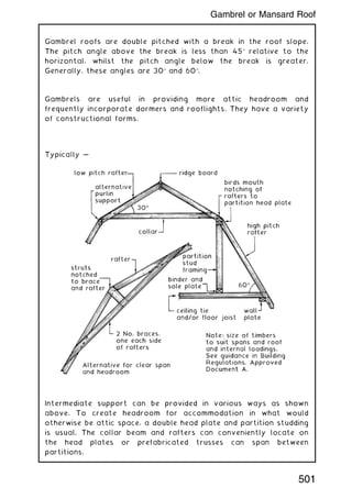
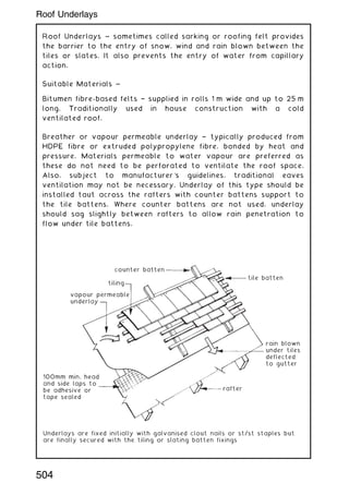
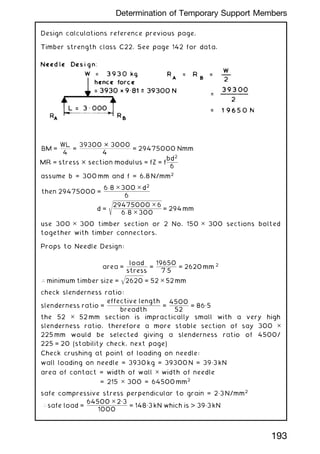
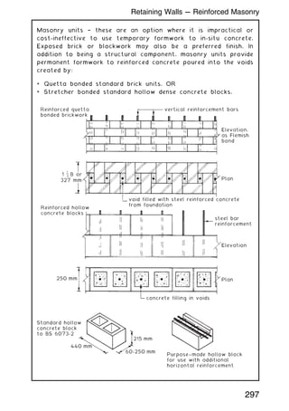
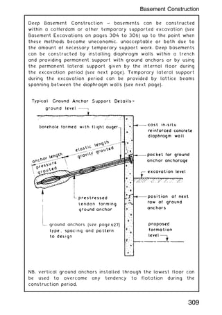
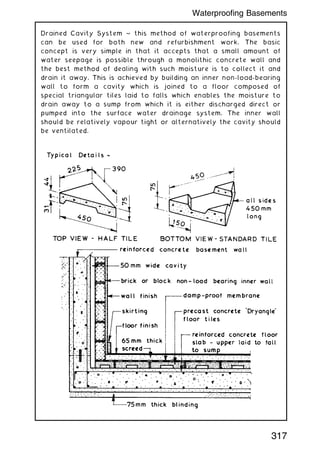
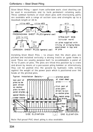
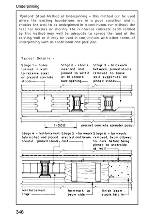
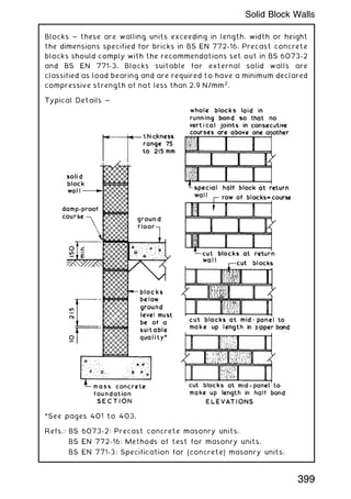
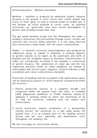
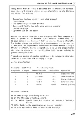
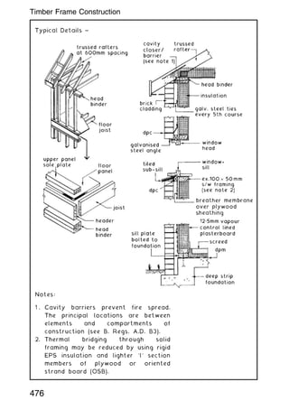
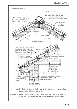
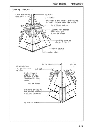
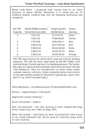
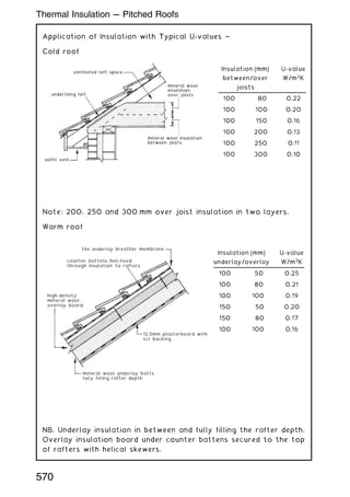
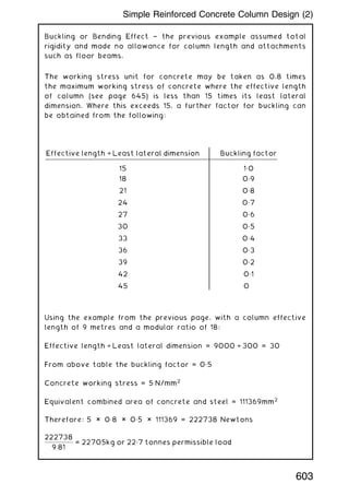
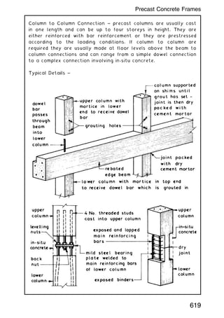
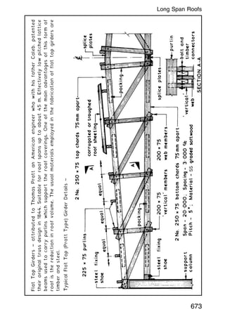
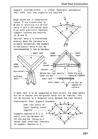
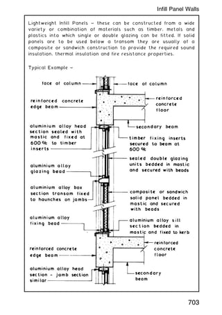
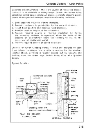
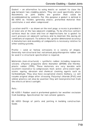
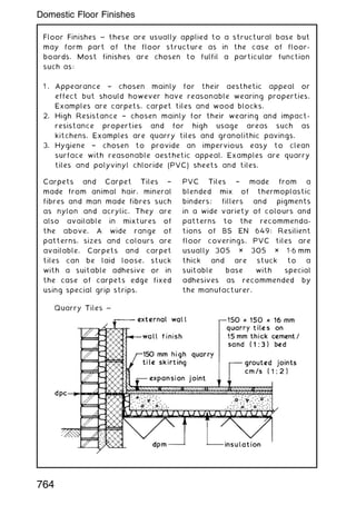
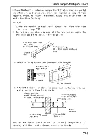
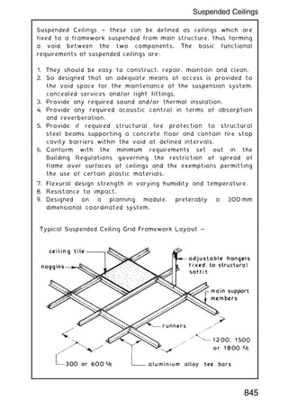
![Note 1: If a cavity closer is also required to function as a cavity
barrier to prevent fire spread, it should provide at least 30
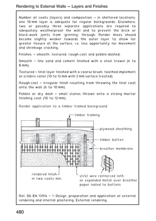
minutes' fire resistance (B. Reg. A.D. B3 Section 6 [Vol. 1] and 9
[Vol. 2]).
Note 2: A breather membrane is an alternative to conventional
bituminous felt as an under-tiling layer. It has the benefit of
restricting liquid water penetration whilst allowing water vapour
transfer from within the roof space. This permits air circulation
without perforating the under-tiling layer.
508
Eaves and Ridge --- Alternative Treatment](https://image.slidesharecdn.com/buildingconstructionhandbook-230110162241-051f4766/85/BUILDING-CONSTRUCTION-HANDBOOK-Tenth-edition-521-320.jpg)
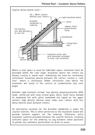
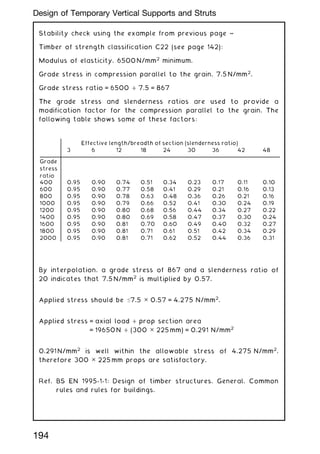
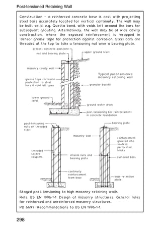
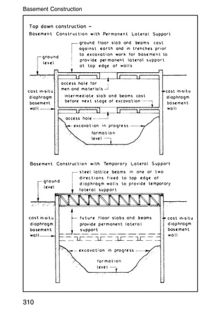
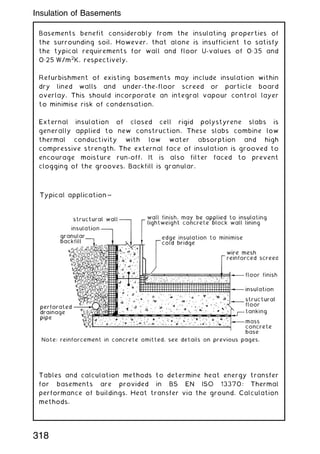
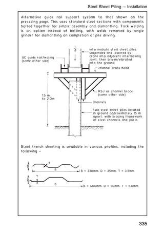
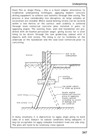
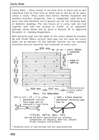
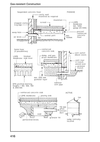
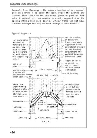
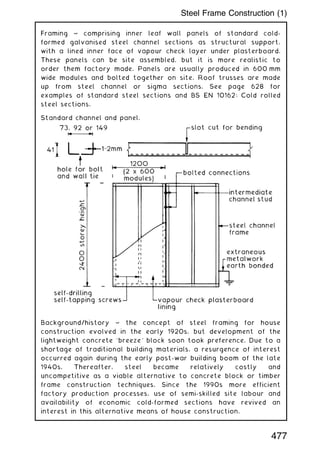
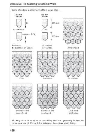
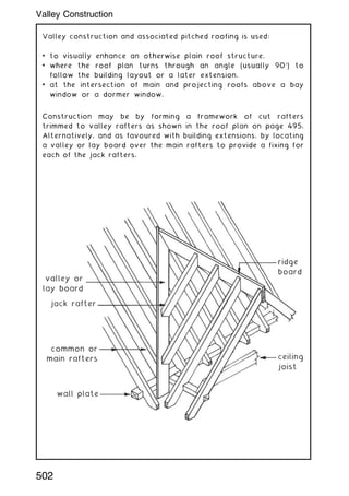
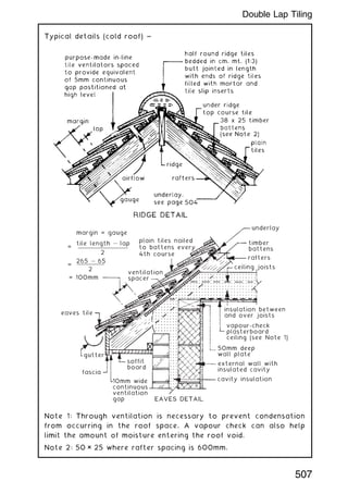
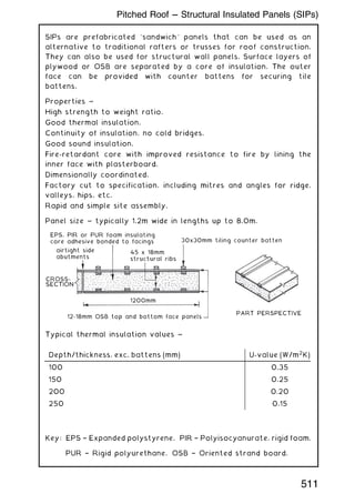
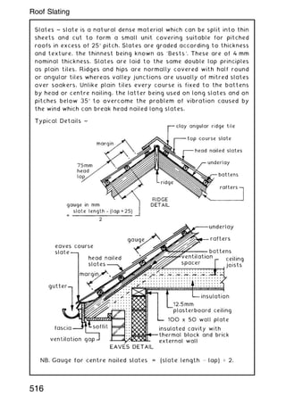
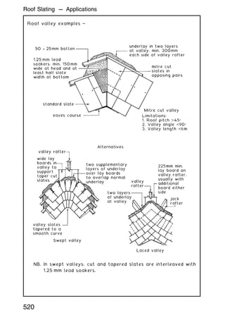
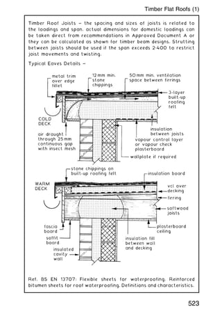
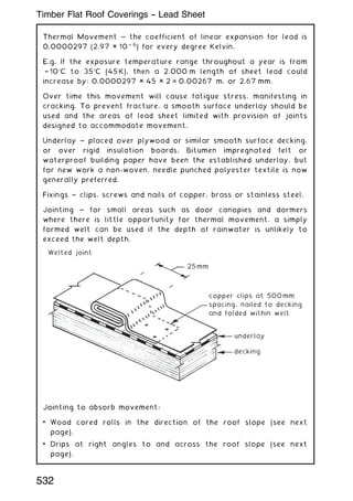
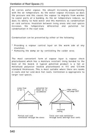
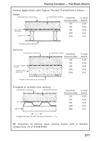
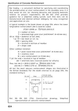
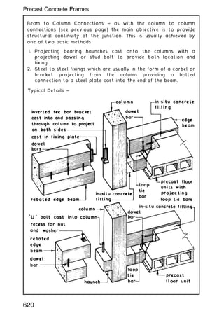
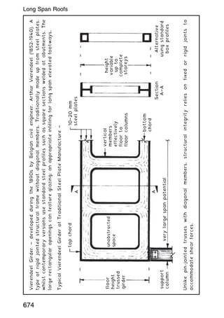
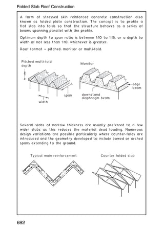
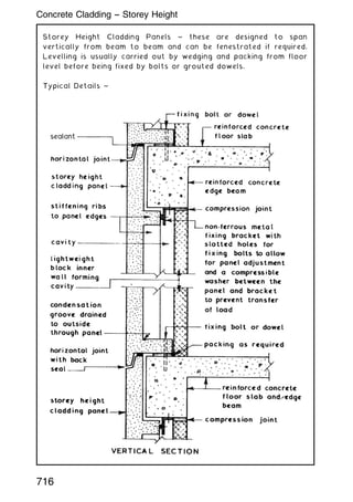
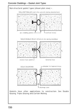
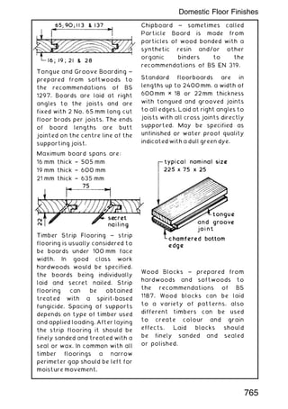
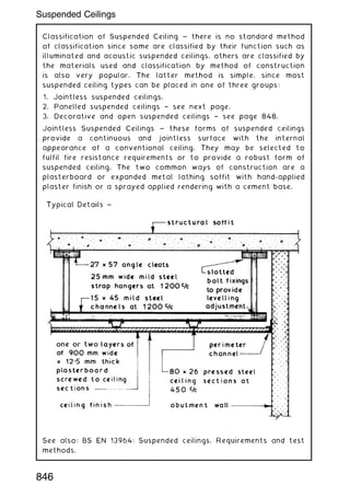
![Insulation in between rafters is an alternative to placing it above
(see page 570). The following details show two possibilities, where
if required supplementary insulation can be secured to the
underside of rafters.
Vapour control layer ~ condensation occurs where warm moist air
contacts a cold layer. This could be in the roof space above
inhabited rooms, where permeable insulation will not prevent
movement of moisture in air and vapour from condensing on the
underside of traditional tile underlay (sarking felt) and bituminous
felt flat roof coverings. Venting of the roof space (see pages
540 to 541) will control condensation.
Alternatively it can be controlled with a well sealed vapour
control layer (for instance, foil [metallised polyester] backed
plasterboard) incorporated in the ceiling lining and used with a
vapour permeable (breather membrane) underlay to the tiling.
Joints and openings in the vcl ceiling (e.g. cable or pipe
penetrations) should be sealed, but if this is impractical ventilation
should be provided to the underside of the tile underlay.
510
Pitched Roof --- Insulation Between Rafters](https://image.slidesharecdn.com/buildingconstructionhandbook-230110162241-051f4766/85/BUILDING-CONSTRUCTION-HANDBOOK-Tenth-edition-523-320.jpg)
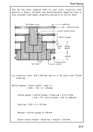
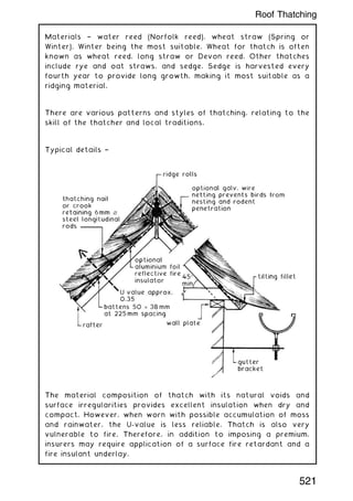
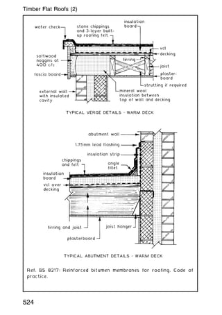
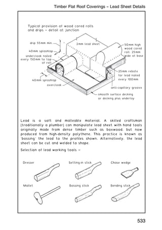
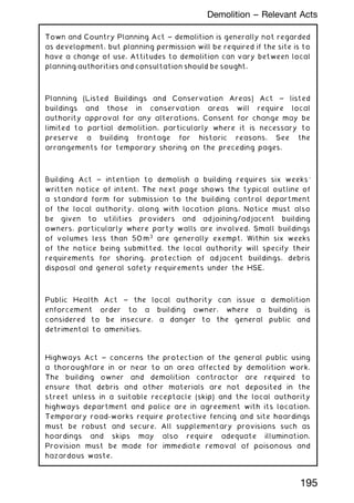
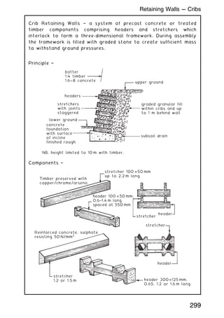
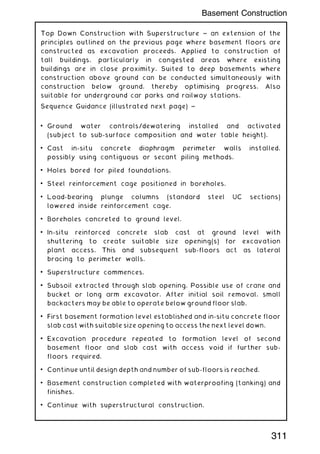
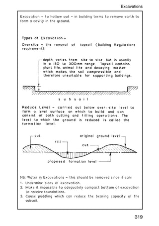
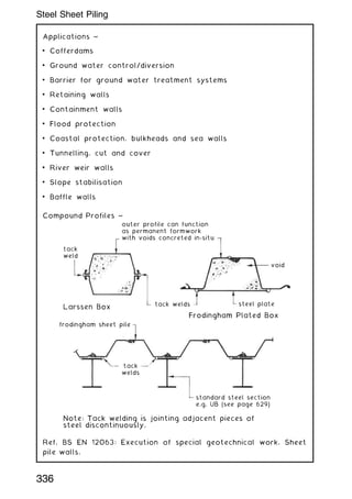
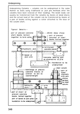
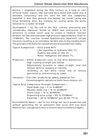
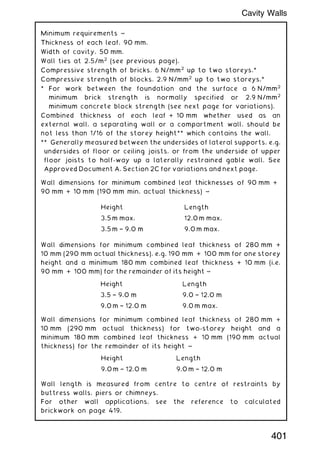
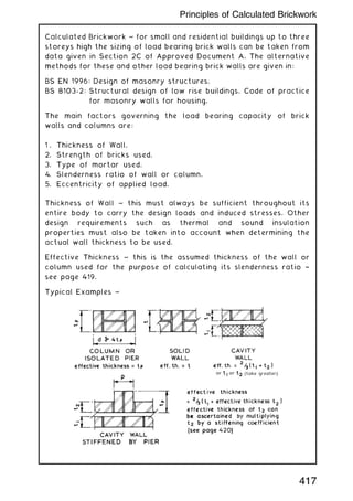
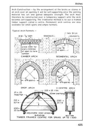
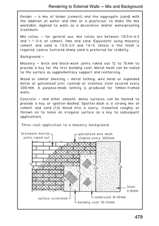
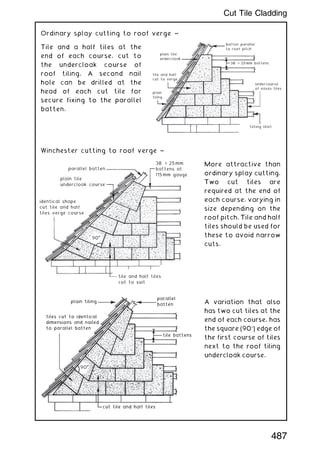
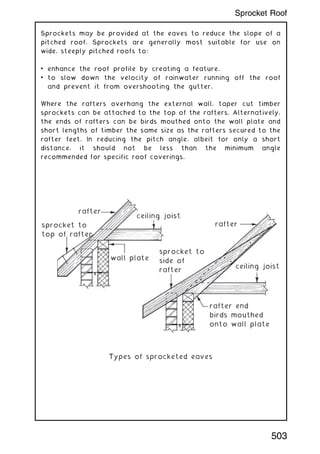
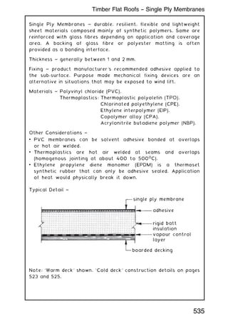
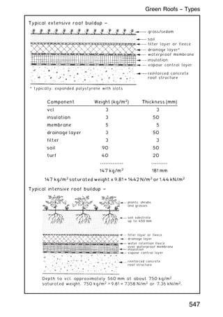
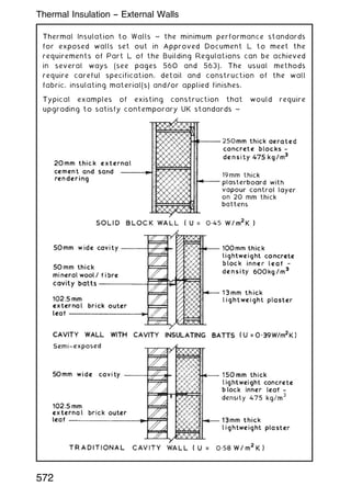
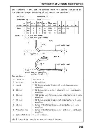
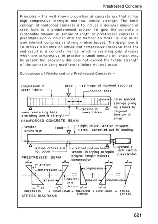
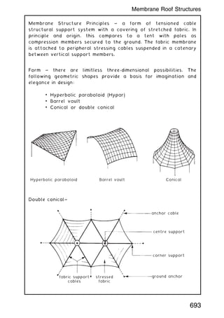
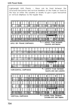
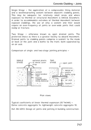
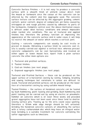
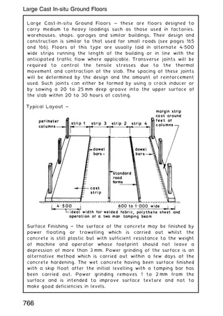
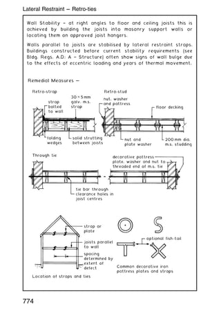
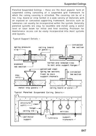
![Spacing of wood cored rolls and drips varies with the thickness
specification of lead sheet. The following is a guide ~
Typical flat roof plan (page 491)
100mm min.
abutment upstand
to wall with
apron flashing
wood cored
roll
see previous
page
drip
verge
fascia downstand
into gutter
B
A
BS EN 12588
thickness (mm)
Maximum distance
between drips (mm) [A]
Maximum distance
between rolls (mm) [B]
1.25 and 1.50 Use for soakers only
1.75 1500 500
2.00 2000 600
2.50 2250 675
3.00 2500 675
3.50 3000 750
534
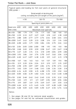
Timber Flat Roof Coverings -- Lead Sheet Application](https://image.slidesharecdn.com/buildingconstructionhandbook-230110162241-051f4766/85/BUILDING-CONSTRUCTION-HANDBOOK-Tenth-edition-547-320.jpg)
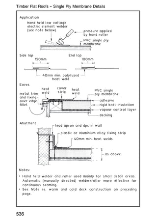
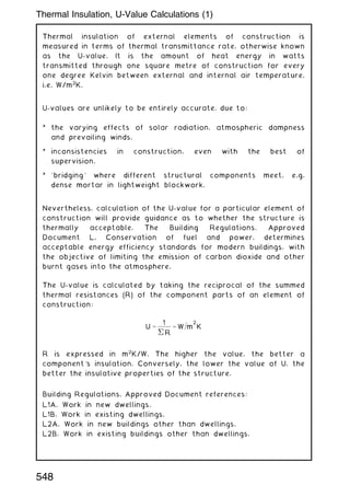
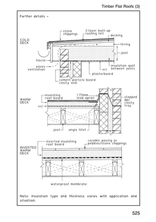
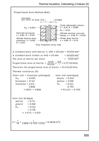
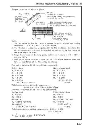
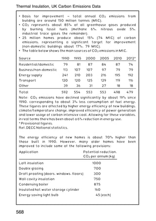
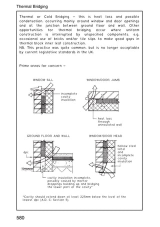
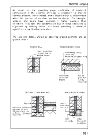
![Various applications to different ground floor situations are
considered in BS EN ISO 13370. The following is an example of a
solid concrete slab in direct contact with the ground. The data
used is from the previous page.
Floor section
Perimeter = 18 m (exposed)
Floor area = 20 m2
for 90 mm insulation = 0.03 W/mK
Characteristic floor dimension = B1
B1
= Floor area ÷ (1/2 exp. perimeter)
B1
= 20 ÷ 9 = 2.222 m
Formula to calculate total equivalent floor thickness for
uninsulated and insulated all over floor:
dt = w + (Rsi + Rf + Rso)
where: dt = total equivalent floor thickness (m)
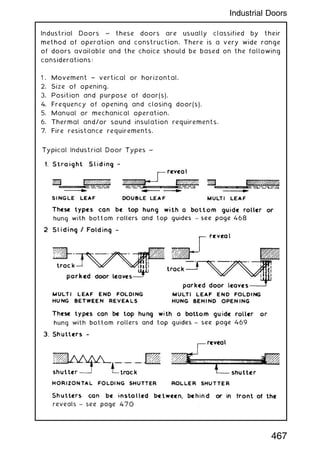
w = wall thickness (m)
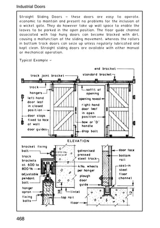
= thermal conductivity of soil (W/mK) [see page 552]
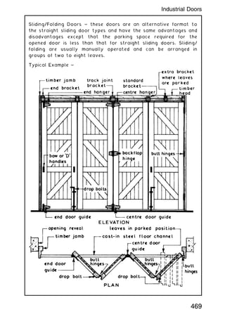
Rsi = internal surface resistance (m2
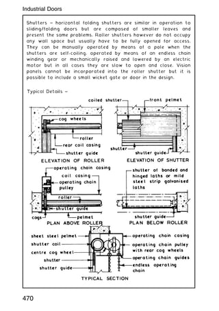
K/W) [see page 550]
Rf = insulation resistance (0.09 ÷ 0.03 = 3 m2
K/W)
Rso = external surface resistance (m2
K/W) [see page 550]
Uninsulated: dt = 0.3 + 1.5 (0.148 + 0 + 0.04) = 0.582m
Insulated: dt = 0.3 + 1.5 (0.148 +3+0.04) = 5.082m
Formulae to calculate U-values ~
Uninsulated or poorly insulated floor, dt B1
:
U = (2) ÷ [(p B1
) + dt] × ln [(p B1
÷ dt) + 1]
Well insulated floor, dt
†
B1
:
U = ÷ [(0.457 × B1
) + dt]
where: U = thermal transmittance coefficient (W/m2
/K)
= thermal conductivity of soil (W/mK)
B1
= characteristic floor dimension (m)
dt = total equivalent floor thickness (m)
ln = natural logarithm
Uninsulated floor ~
U = (2 × 1.5) ÷ [(3.142 × 2.222) + 0.582] × ln [(3.142 × 2.222) ÷ 0.582 + 1]
U = 0.397 × ln 12.996 = 1.02 W/m2
K
Insulated floor ~
U = 1.5 ÷ [(0.457 × 2.222) +5.082] = 1.5 ÷ 6.097 = 0.246 W/m2
K
NB. Compares with the tabulated figure of 0.250 W/m2
K on the
previous page.
554
Thermal Insulation, Calculating U-Values (1)](https://image.slidesharecdn.com/buildingconstructionhandbook-230110162241-051f4766/85/BUILDING-CONSTRUCTION-HANDBOOK-Tenth-edition-567-320.jpg)
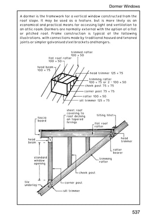
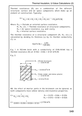
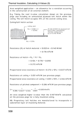
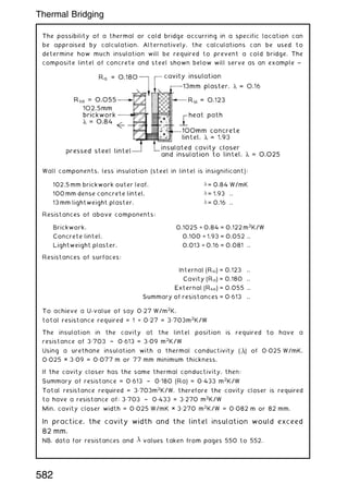
![Combined Method (Wall)
This method considers the upper and lower thermal resistance (R)
limits of an element of structure. The average of these is
reciprocated to provide the U-value.
Formula for upper and lower resistances =
1
(Fx÷ Rx)
Where: Fx = Fractional area of a section
Rx = Total thermal resistance of a section
Using the wall example from the previous page:
Upper limit of resistance (R) through section containing blocks †
(Rso, 0„055) + (brkwk, 0„122) + (ins, 2„631) + (blocks, 0„555) + (plstr,
0„081) + (Rsi, 0„123) = 3„567 m2
K/W
Fractional area of section (F) = 93„43% or 0„934
Upper limit of resistance (R) through section containing mortar †
(Rso 0„055) + (brkwk, 0„122) + (ins, 2„631) + (mortar, 0„114) + (plstr,
0„081) + (Rsi, 0„123) = 3„126 m2
K/W
Fractional area of section (F) = 6„57% or 0„066
The upper limit of resistance =
1
(0„943 ÷ 3„567) + (0„066 ÷ 3„126)
= 3„533m2
K=W
Lower limit of resistance (R) is obtained by summating the
resistance of all the layers †
(Rso, 0„055) + (brkwk, 0„122) + (ins, 2„631) + (bridged layer,
1 ÷ [0„934 ÷ 0„555] + [0„066 ÷ 0„114] = 0„442) + (plstr, 0„081) +
(Rsi, 0„123) = 3„454 m2
K/W
Total resistance (R) of wall is the average of upper and lower
limits = (3„533 + 3„454) ÷ 2 = 3„493 m2
K/W
U-value =
1
R
=
1
3„493
= 0„286 W=m
2
K
NB. Both proportional area and combined method calculations
require an addition of 0„020 W/m2
K to the calculated U-value. This
is for vertical twist type wall ties in the wide cavity. See page
400 and note 2 on page 552.
556
Thermal Insulation, Calculating U-Values (3)](https://image.slidesharecdn.com/buildingconstructionhandbook-230110162241-051f4766/85/BUILDING-CONSTRUCTION-HANDBOOK-Tenth-edition-569-320.jpg)
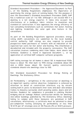
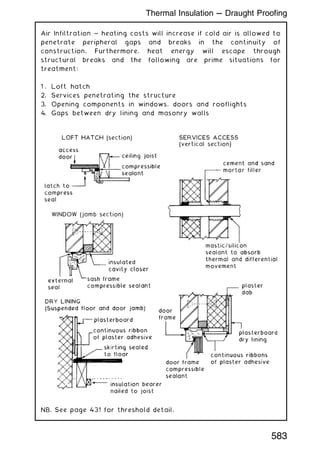

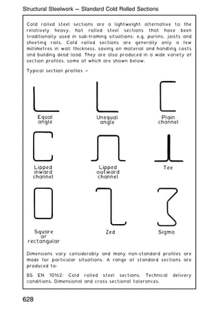
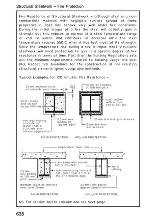
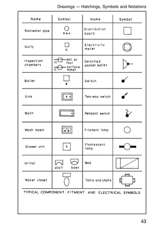
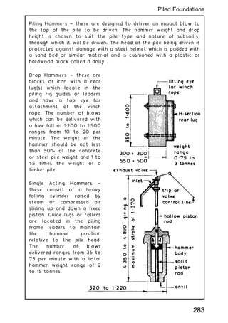
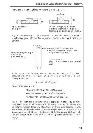
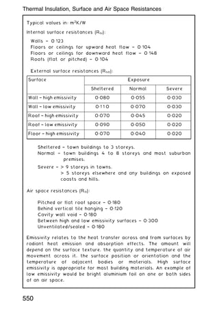
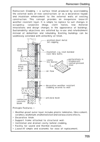
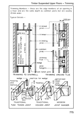
![Section Factors † these are criteria found in tabulated fire
protection data such as the Loss Prevention Certification Board's
Standards. These factors can be used to establish the minimum
thickness or cover of protective material for structural sections.
This interpretation is usually preferred by buildings insurance
companies, as it often provides a standard in excess of the Building
Regulations. Section factors are categorised: 90, 90†140 and
140. They can be calculated by the following formula:
Section Factor = Hp/A (m1
)
Hp = Perimeter of section exposed to fire (m)
A = Cross sectional area of steel (m2
) [see BS 4-1 or Structural
Steel Tables]
Examples:
Hp = (2 × 124„3) + (2 × 306„6) + 2(124„3 † 8) = 1„0944 m
A = 53„2 cm2
or 0„00532 m2
Section Factor, Hp/A = 1„0944/0„00532 = 205
As beam above, but three sides only exposed
fire protection
UB
compartment concrete
floor, f.r. = 120 minutes
Hp = 124„3 + (2 × 306„6) + 2(124„3 † 8) = 0„9701 m
A = 53„2 cm2
or 0„00532 m2
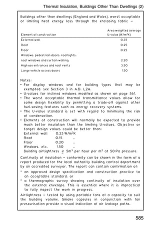
Section Factor, Hp/A = 0„9701/0„00532 = 182
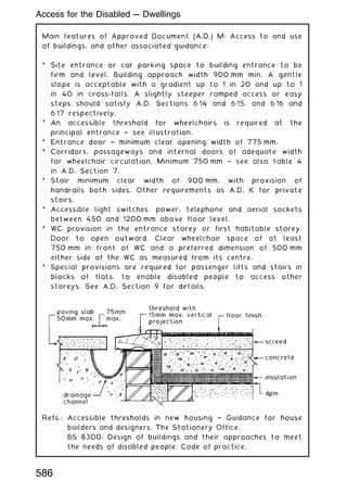
639
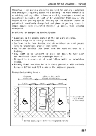
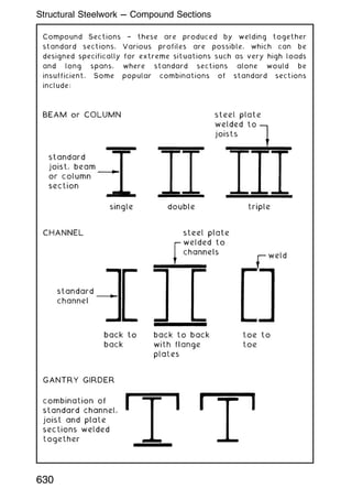
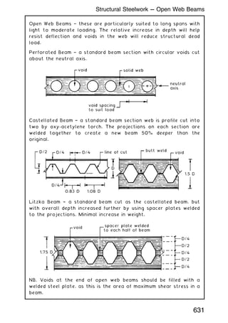
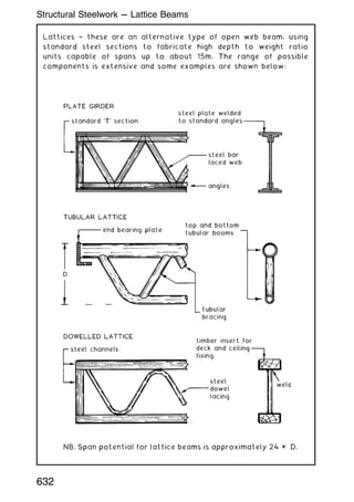
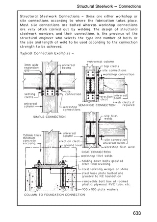
Structural Steelwork -
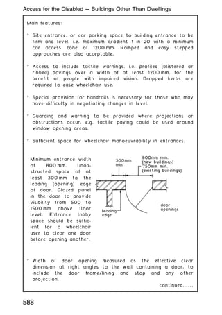
-- Fire Protection](https://image.slidesharecdn.com/buildingconstructionhandbook-230110162241-051f4766/85/BUILDING-CONSTRUCTION-HANDBOOK-Tenth-edition-652-320.jpg)
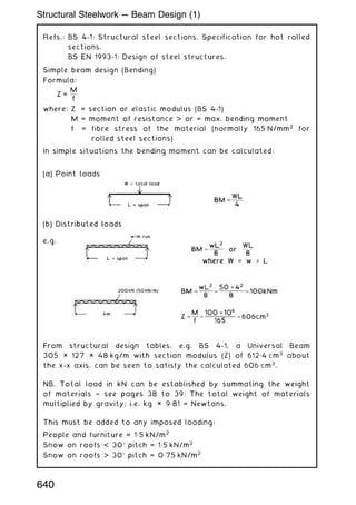
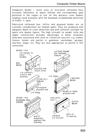
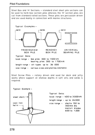
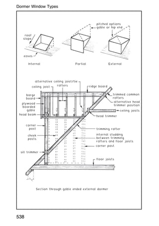
![PSB ~ otherwise known as a parallam beam. Fabricated from long
strands of softwood timber bonded with a phenol-formaldehyde
adhesive along the length of the beam to produce a structural
section of greater strength than natural timber of equivalent section.
Used for beams, lintels, structural framing and trimmer sections around
floor openings in spans up to 20 m. Can also be used vertically as
columns.
Standard sizes ~ range from 200 × 45 mm up to 406 × 178 mm.
longitudinal strands
of softwood timber
adhesive coated
and bonded under
heat and pressure
Standard lengths 12, 15 and 18m
Typical grade stresses [N/mm2
] (compare with sw timber, page 142) ~
Variation ~ for spans in excess of 20 m or for high loads, a flitch
beam as shown on the previous page can be made by bolting a
steel plate (typically 10 or 12 mm) between two PSBs.
Ref. BBA Agr
ement Certificate No. 92/2813.
Bending parallel to grain 16.8
Tension parallel to grain 14.8
Compression parallel to grain 15.1
Compression perpendicular to grain 3.6
Shear parallel to grain 2.2
Modulus of elasticity (mean) 12750
Average density 740 kg/m3
656
Parallel Strand Beam (PSB)](https://image.slidesharecdn.com/buildingconstructionhandbook-230110162241-051f4766/85/BUILDING-CONSTRUCTION-HANDBOOK-Tenth-edition-669-320.jpg)
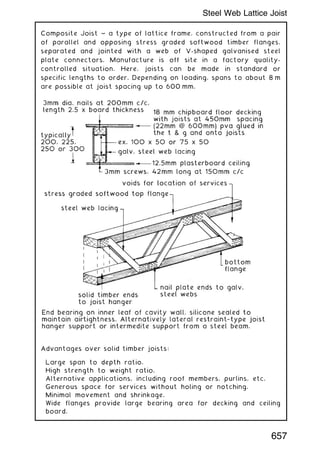
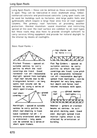
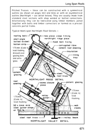
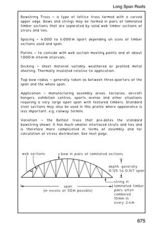
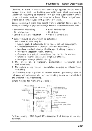
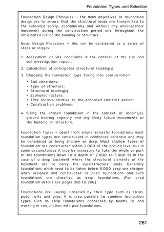
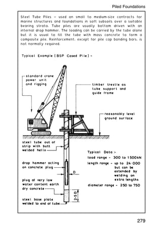
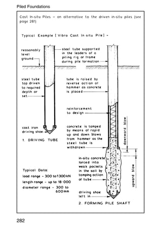
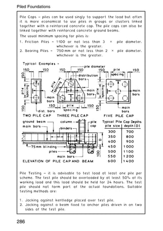
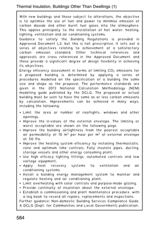
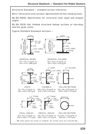
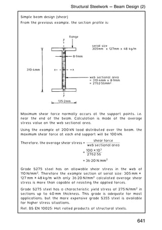
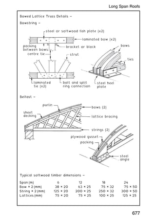
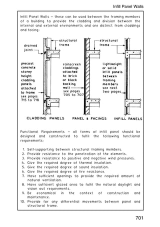
![Belfast Truss ~ established as one of the earliest forms of
bowstring truss for achieving an efficient and economical roof
construction over large spans. It was first used in the latter part
of the 19th century and early part of the 20th century for
industrial and agricultural buildings in response to the need for
space uninterrupted by walls and columns within production,
assembly and storage areas. A contribution to the name was a
truss design devised by Messrs D. Anderson and Son, Ltd of
Belfast, for supporting their patent roofing felt.
lattice location alternative
45°
A = purlins at about
1.000m spacing
centre
line
radius
(see
calculation)
spans up to
about 30.000m
A
A
span
8
span
2
Centre line radius = [(0.5 × span)2
+ (rise)2
] ÷ (2 × rise)
E.g. A 16 m span with a rise of 0.125 × span.
Therefore, rise of truss = 0.125 × 16 = 2 m.
Centre line radius = [(0.5 × 16)2
+ (2)2
]÷(2 × 2)
= 68÷4 = 17 m.
676
Long Span Roofs](https://image.slidesharecdn.com/buildingconstructionhandbook-230110162241-051f4766/85/BUILDING-CONSTRUCTION-HANDBOOK-Tenth-edition-689-320.jpg)

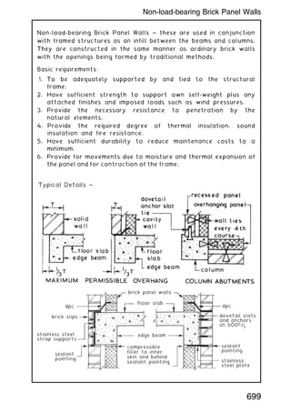


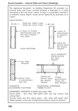
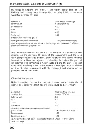
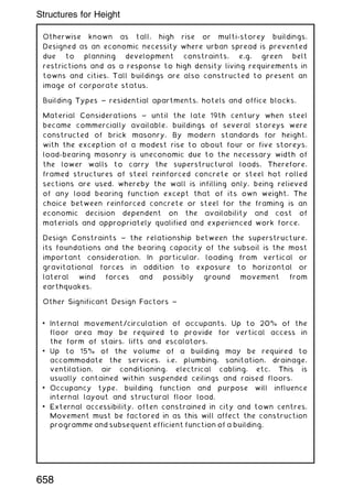
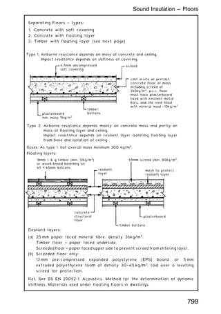
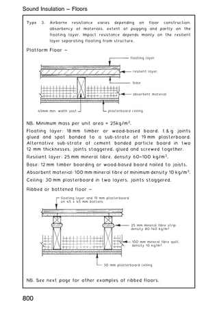
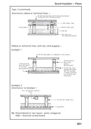
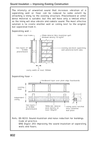
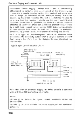
![Separating Walls ~ types:
1. Solid masonry
2. Cavity masonry
3. Masonry between isolating panels
4. Timber frame
Material
A
Density
of A
[kg/m3
]
Finish B Combined mass A +
B (kg/m2
)
Thickness
C [mm]
Coursing
D [mm]
Brickwork 1610 13 mm
lwt. pl.
375 215 75
.. .. .. .. 12„5 mm
pl. brd.
.. .. .. .. .. ..
Concrete
block
1840 13 mm
lwt. pl
415 .. .. 110
.. .. 1840 12„5 mm
pl. brd
.. .. .. .. 150
In-situ
concrete
2200 Optional 415 190 n/a
Material
A
Density of
A [kg/m3
]
Finish B Mass
A + B
(kg/m2
)
Thickness
C [mm]
Coursing
D [mm]
Cavity
E [mm]
Bkwk. 1970 13 mm
lwt. pl.
415 102 75 50
Concrete
block
1990 .. .. 100 225 ..
Lwt. conc.
block
1375 ..
or 12.5 mm
pl. brd.
300 100 225 75
797
Sound Insulation --- Walls](https://image.slidesharecdn.com/buildingconstructionhandbook-230110162241-051f4766/85/BUILDING-CONSTRUCTION-HANDBOOK-Tenth-edition-810-320.jpg)
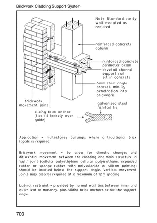
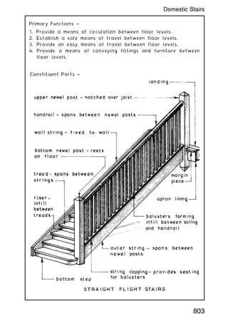
![Panel materials † B:
(a) Plasterboard with cellular core plus plaster finish, mass 18 kg/
m2
. All joints taped. Fixed floor and ceiling only.
(b) 2 No. plasterboard sheets, 12„5 mm each, with joints staggered.
Frame support or 30 mm overall thickness.
Absorbent material † quilting of unfaced mineral fibre batts with a
minimum density of 10 kg/m3
, located in the cavity or frames.
Core material A Density of A
[kg/m3
]
Mass A
(kg/m2
)
Thickness C
(mm)
Coursing D
(mm)
Cavity
(mm)
Brickwork 1290 300 215 75 n/a
Concrete block 2200 300 140 110 n/a
Lwt. conc. block 1400 150 200 225 n/a
Cavity bkwk. or
block
any any 2 × 100 to suit 50
Thickness (mm) Location
25 Suspended in cavity
50 Fixed within one frame
2 × 25 Each quilt fixed within each frame
798
Sound Insulation --- Walls](https://image.slidesharecdn.com/buildingconstructionhandbook-230110162241-051f4766/85/BUILDING-CONSTRUCTION-HANDBOOK-Tenth-edition-811-320.jpg)
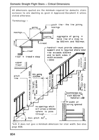
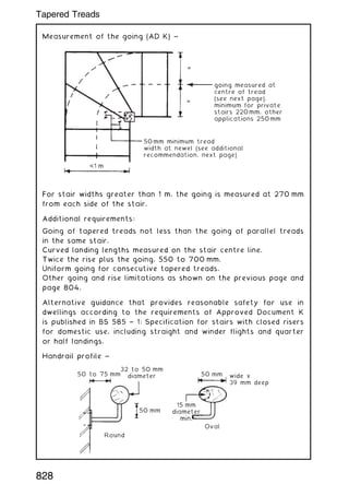
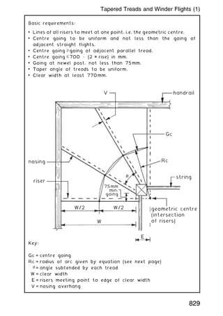
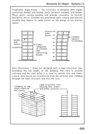
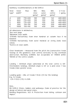
![To check whether the design for winder flights will comply with
recommended dimensions, measurements can be taken from scale
drawings or calculations may be applied.
Calculations ~
Gc = 2Rc (sin ÷ 2)
where Rc ([W ] E) (V)
= ÷ + +
2 2 2
E.g. W = 770 mm
E = 150 mm
V = 16 mm
Rc ([ ] )
= ÷ + +
770 2 150 16
2 2
( )
Rc = + +
( )
385 150 256
2
Rc ( )
= +
535 256
2
Rc mm
= + = =
286225 256 286481 535
Gc ( )
= × ˚ ÷
2 535 30 2
sin
where sin 30 = 0.5
Gc ( ) mm
= × = =
1070 0 5 2 267
.
In most applications the winder flight will turn through a 90 angle on
plan. Therefore, the angle subtended by each of three treads will be
30, i.e. = turn angle ÷ N, where N = the number of winders.
For four winders, = 90 ÷ 4 = 22.5.
If the turn angle is other than 90 then = (180 † turn angle) ÷N.
E.g. Turn angle of 120 with two winders, = (180 † 120) ÷ 2 = 30.
Refs.: BS 585-1: Wood stairs. Specification for stairs with closed
risers for domestic use, including straight and winder flights
and quarter or half landings.
BS 5395-1: Code of practice for the design of stairs with
straight flights and winders.
830
Tapered Treads and Winder Flights (2)](https://image.slidesharecdn.com/buildingconstructionhandbook-230110162241-051f4766/85/BUILDING-CONSTRUCTION-HANDBOOK-Tenth-edition-843-320.jpg)
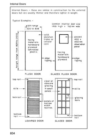
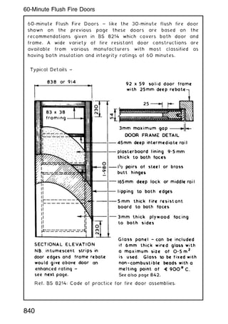
![Fire Doorset ~ a `complete unit consisting of a door frame and a
door leaf or leaves, supplied with all essential parts from a single
source'. The difference between a doorset and a fire doorset is
that the latter is endorsed with a fire certificate for the complete
unit. When supplied as a collection of parts for site assembly, this
is known as a door kit.
Fire Door Assembly ~ a `complete assembly as installed, including
door frame and one or more leaves, together with its essential
hardware [ironmongery] supplied from separate sources'. Provided
the components to an assembly satisfy the Building Regulations †
Approved Document B, fire safety requirements and standards for
certification and compatibility, then a fire door assembly is an
acceptable alternative to a doorset.
Fire doorsets are usually more expensive than fire door assemblies,
but assemblies permit more flexibility in choice of components. Site
fixing time will be longer for assemblies.
(Quotes from BS EN 12519: Windows and pedestrian doors.
Terminology.)
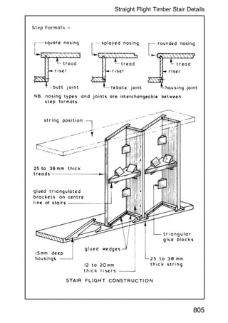
Fire Door ~ a fire door is not just the door leaf. A fire door
includes the frame, ironmongery, glazing, intumescent core and
smoke seal. To comply with European market requirements,
ironmongery should be CE marked (see page 75). A fire door should
also be marked accordingly on the top or hinge side. The label
type shown below, reproduced with kind permission of the British
Woodworking Federation, is acceptable.
Company's
Name
Company's Own
Telephone no.
CERTIFIRE
Certificate no.
Unique number = Full traceability
Sequential no.
Ref. BS 8214: Code of practice for fire door assemblies.
838
Fire Doorsets and Fire Door Assemblies](https://image.slidesharecdn.com/buildingconstructionhandbook-230110162241-051f4766/85/BUILDING-CONSTRUCTION-HANDBOOK-Tenth-edition-851-320.jpg)
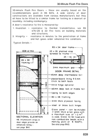
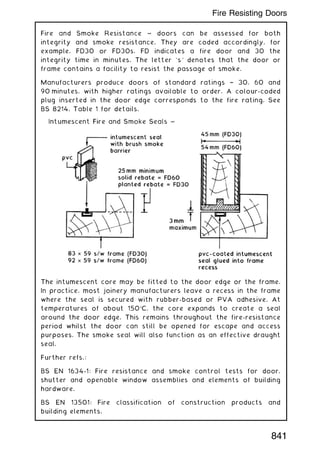

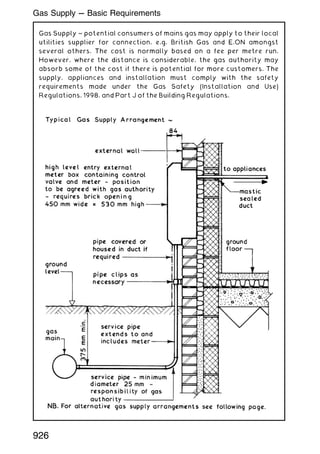
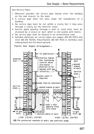
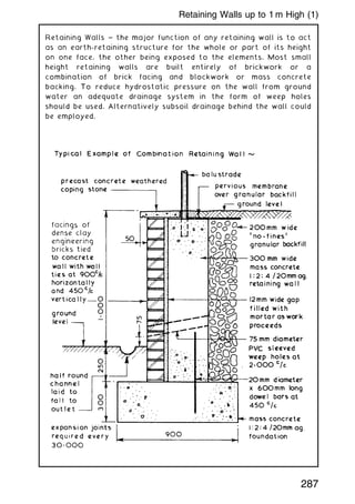
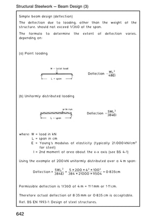
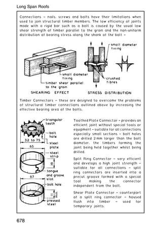
![Fire Protection of Services Openings ~ penetration of compartment
walls and floors (zones of restricted fire spread, e.g. flats in
one building) by service pipes and conduits is very difficult to
avoid. An exception is where purpose-built service ducts can be
accommodated. The Building Regulations, Approved Document B3:
Sections 7 [Vol. 1] and 10 [Vol. 2] determines that where a pipe
passes through a compartment interface, it must be provided with
a proprietary seal. Seals are collars of intumescent material which
expands rapidly when subjected to heat, to form a carbonaceous
charring. The expansion is sufficient to compress warm plastic and
successfully close a pipe void for up to four hours.
In some circumstances fire stopping around the pipe will be
acceptable, provided the gap around the pipe and hole through the
structure are filled with non-combustible material. Various
materials are acceptable, including reinforced mineral fibre, cement
and plasters, asbestos rope and intumescent mastics.
Pipes of low heat resistance, such as PVC, lead, aluminium alloys
and fibre cement, may have a protective sleeve of non-combustible
material extending at least 1m either side of the structure.
939
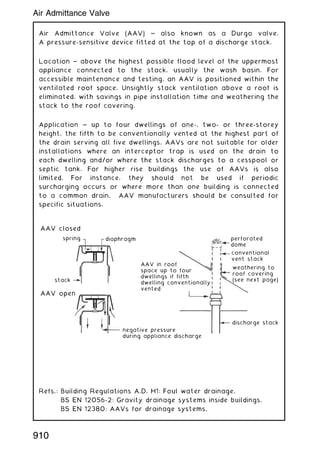
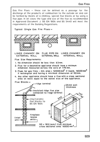
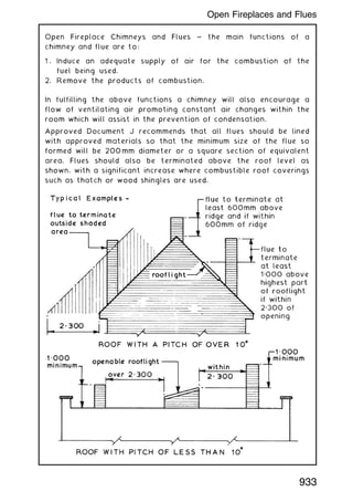
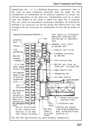
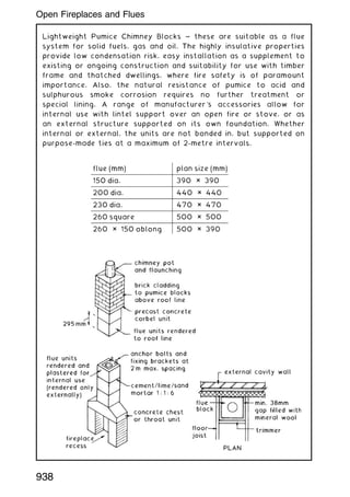
Services --- Fire Stops and Seals](https://image.slidesharecdn.com/buildingconstructionhandbook-230110162241-051f4766/85/BUILDING-CONSTRUCTION-HANDBOOK-Tenth-edition-952-320.jpg)


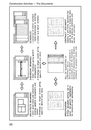
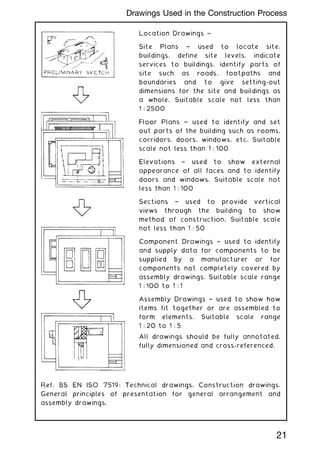
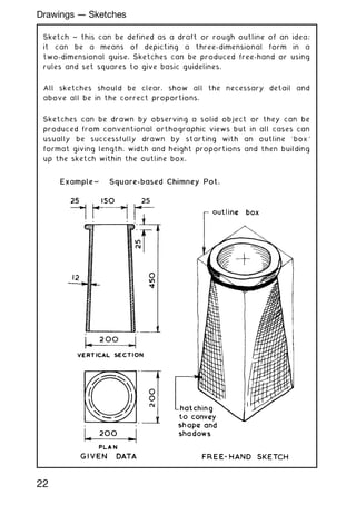
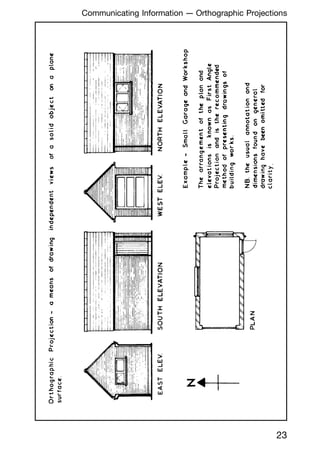
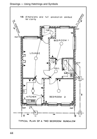
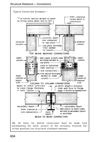
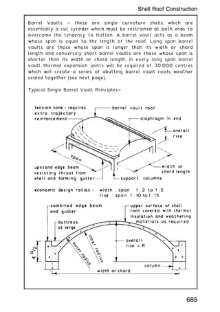
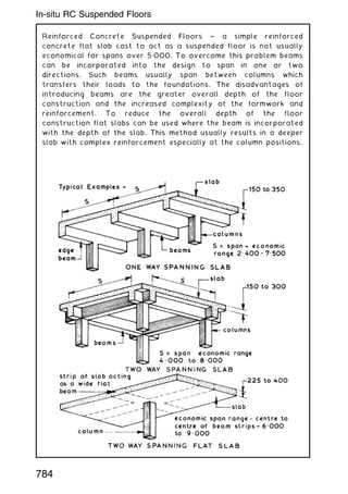
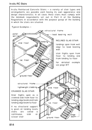
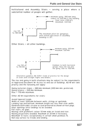
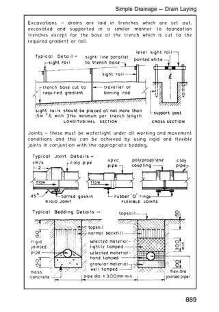
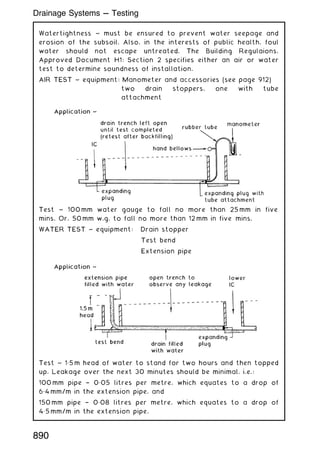
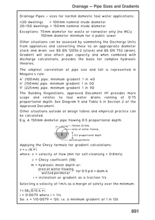
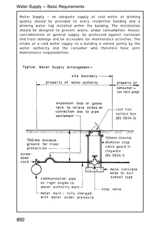
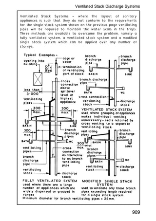
1:2500 to 1:5 Assembly Drawings † used to identify components and show their assembly and fixing. Suitable scale range 1:50 to 1:5 Detail Drawings † used to show construction details not fully shown on assembly drawings. Suitable scale range 1:10 to 1:1 21 Construction Drawings --- Types and Scales


