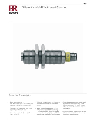
Differential-Hall-Effect based Sensors
•	 Speed range covering:
	 from close to zero up to 12,000 pulses / sec.
	 (response time max. 40 microseconds)
•	 Clearance to the rotating part up to 4 mm
	 (depending on the profile size)
•	 Temperature range –40 °C … +125 °C
	 (–40 … +255 °F)
•	 Differential principle hinders the influence of
	 external magnetic fields and of machine
	 vibration
•	 Sealed stainless steel enclosure (1.4305)
	 with protection grade IP67 and allowing
	 > 200 bar pressure to sensor tip. Available
	 for connection via  tight plug, or with firmly
	 attached cable (standard or Teflon insulated)
•	 Powerful square wave output signal equally
	 high over the entire speed range. Level
	 approximately that of the supply voltage.
	 Adequate for signal transmission over more
	 than 500 m.
•	 Accepting fine and coarse profiles, as gear
	 wheels, slots, cams, holes in any ferrous
	 material, or rotating magnets.
Outstanding Characteristics:
A5S
Appropriate for any speed detection of rotating steel profile, unless the application has a special
requirement as listed below.
Series A5S05 … A5S09
Series A5S10 … A5S13 Speed Detection within Explosion Hazardous areas. These sensors are intrinsically safe when
connected to our barrier units D461. No further precautions required in the Ex-area,
with installation and cabling.
Series A5S30 … A5S33 Detection of speed and direction by only one sensor. Speed signalized as the frequency of
a pulse train, direction as the high or low state of a binary DC voltage.
Series A5S14 … A5S17 For speed and direction sensing as  A5S30 … A5S33…, but under intrinsically safety
requirements for Ex-hazardous areas.
Series A5S40 … A5S43 Providing 2 phase-shifted speed pulse trains, for a separate direction monitoring with
failure detection.
The Various Series and their Range of Application
Each series includes several differing dimen-
sions and connection modes, but all with the
same functional characteristics. For details and
ordering Nos. see the following pages.
Installation, profile size, and clearance
to target
Flush placement into any material, close to
an other sensor. The allowed clearance (gap)
to the target depends on its size: with the
smallest detectable profile size of module 0.8
(pitch 30) it is <1 mm, a profile size of module
4 (pitch 6) or more allows a maximum gap of
nearly 4 mm.
Please pay special attention to the application
notes on page 7.
Connection Modes
All A5S… sensors are available with a hard-
wired cable attached, or with a socket accept-
ing plug-in connectors. This is the easier way
to handle a long cable. Such can be provided
in standard (up to 85 °C) or high temp (up to
125 °C)Teflon quality. With a straight or angular
plug, in metallic or plastic enclosure, all tight to
IP 67. Or, the connectors only.
For duty under liquids however, or with narrow
space applications, the firm cable is the better
choice. Available with both insulation qualities,
and any requested length.
The Hall effect (named for its discoverer) utilizes the fact, that a mag-
netic field may generate a voltage within a semi-conductor. And  does
this independent of its rate of change (i.e. speed of motion) – unlike
the induction effect of magnetic pick-ups, which rely on the rate and
therefore are weak at low speed. The sensors A5S… include the neces-
sary magnet (M) and the hall element chip (E). With the profile passing
by, the magnetic field varies, thereby creating the signal voltage within
the chip. Here it is important to keep in mind, that the signal  does not
fade at low speed.
The Differential Hall Effect Principle
It engages a twin chip hall element, and the signal amplifier (V) uses
only the difference between both. It is then amplified to provide the
power square wave output.
Its Advantages:
By its nature, this differential principle compensates target vibrations.
And it balances an external magnetic field. Both important aspects for a
reliable signal.
VME
moving profile
sensor output
Function Principle
02
Plug-in version shown
with angled connector
Version with firmly
attached cable
Plug-in version shown
with straight connector
Design Versions
03
Sensor Series
Sensor Series A5S05…A5S09
Application
Standard for speed detection with a single
trace output.
Output signal
Square wave pulses with sequence according
to the target profile (1:1 with a standard gear).
Amplitude (without load) close to supply volt-
age. Its power output pulls or sinks a load as
heavy as 25 mA. This allows a transmission
distance of  more than 500 m (≥1500 ft),
allowing a high frequency max. 12 kHz. The
output high level then may drop by max 2
Volts, the output low level then may increase
by max 2 volts over zero. Output protected
against short circuit.
Power Supply
Supply voltage +5 V …+30 V DC. Current ap-
prox. 15 mA + load current (may increase with
large distance transmission and high signal
frequency up to 60 mA). Safe against polarity
error.
Dimensions
A number of different metric and UNF mount-
ing threads (D) are available, with varied length
(L). The opposite table lists the preference
dimensions. Customized dimensions have a
longer lead time, and a higher price.
In addition, we offer a version with smooth
shaft  (16 mm Ø), mounting by means of a
seal packing.
Preference Dimensions
Mounting	 Thread length	 Series
thread D 	 L (mm)	 No.
M12 x 1	 50,80,120	 A5S07
M14 x 1,5	 50,90,154,204	 A5S05
M18 x 1	 48, 94	 A5S08
M22 x 1	 48, 94	 A5S09
5/8-18UNF2A	 38,48,100,165	 A5S08…A
5/8-18UNF2A	 38,48,100,165	 A5S08…B *
5/8-18UNF2A	 38,48,100,165	 A5S08…C **
*)	
with hexagonal rear flange end and firmly
attached PTFE (Teflon) cable.
**)
with hexagonal rear flange, 1/2 NPT inside
thread, and firmly attached PTFE (Teflon) cable.
Specific sheets are available for these versions.
Sensor Series A5S10…A5S13
Application
Speed detection within a
hazardous area.
Protection Class
Approved for Intrinsic Safety according to
ATEX as II 1 G EEx ia IIC T4 / T6 with correct
supply provided.
Output signal
Square wave pulses with sequence according
to the target profile (1:1 with a standard gear).
Amplitude (without load) close to supply volt-
age. Its power stage pulls up or sinks a load
as heavy as 25mA. This allows a transmis-
sion distance of more than 500 m (≥1500 ft),
allowing a high frequency max. 12 kHz. The
output level then drops by approximately 2 V,
only. Output protected against short circuit.
Our recommended Isolating Barrier D461
provides a square wave output of 24 V level
and an additional path allowing sensor supply
monitoring.
Power Supply
By an approved source ensuring max.
+9.9 V and 64 mA. We recommend our
Isolating Barrier D461, which additionally
ensures the Intrinsically safe signal path. See
seperate sheet “Isolating Barriers D461”.
Dimensions
A number of different metric and UNF mount-
ing threads (D) are available, with varied length
(L). The opposite table lists the preference
dimensions. Customized dimensions have a
longer lead time, and a higher price.
In addition, we offer a version with smooth
shaft  (16 mm Ø), mounting by means of a
seal packing.
Preference Dimensions
Mounting	 Thread length	 Series
thread D 	 L (mm)	 No.
M12x1	 50, 80, 120	 A5S12
M14x1,5	 50,90,154,204	 A5S13
M18x1	 48, 94	 A5S10
M22x1	 48, 94	 A5S11
5/8-18UNF2A	 38,48,100,165	 A5S10…A
5/8-18UNF2A	 38,48,100,165	 A5S10…C *
*)
with hexagonal rear flange, 1/2 NPT inside
thread, and firmly attached PTFE (Teflon) cable.
Specific sheets are available for these versions.
04
Sensor Series A5S30…A5S33
Application
Detection of speed and sense of rotation by a
single sensor. Immediate response to motion
reverse. Fitting our evaluating units 124.1S2
and systems E16. For use on pumps, turn
gears, machine tools, test installations.
Output signal
Speed signal as square wave pulses with
sequence according to the target profile (1:1
with a standard gear wheel). Sense of rotation
as a DC-binary signal (high = forward, low
= reverse). Amplitude (without load) close
to supply voltage. Its power stage pulls up
or sinks a load as heavy as 25mA. Outputs
protected against short circuit.
Power Supply
Supply voltage +5 V …+30 V DC.
Current approx. 20 mA + load current (may
increase with longer distance transmission and
high signal frequency up to 60mA). Sensor
safe against polarity error.
Principle of direction detecting
The sensor includes two Differential-Hall-Effect
elements. They sequentially detect the profile
edges passing. From the time sequence,
the logic calculates the actual sense of their
motion, converting it into a high / low state of
the output. Thereby, it immediately detects a
reversal after any edge, independent of the
shape of the profile. Minimum division size
6 mm. A delay or hysteresis in response, if
required, may be introduced by the evaluating
unit.  
Dimensions
A number of different metric and UNF mount-
ing threads (D) are available, with varied length
(L). The table lists the preference dimensions.
Customized dimensions have a longer lead
time, and a higher price.
In addition, we offer a version with smooth
shaft  (16 mm Ø), mounting by means of a
seal packing.
Preference Dimensions
Mounting	 Thread length	 Series
thread D 	 L (mm)	 No.
M12 x 1	 80, 120	 A5S33
M14 x 1,5	 90,154,204	 A5S31
M18 x 1	 94	 A5S30
M22x1	 94	 A5S32
5/8-18UNF2A	 38,48,100,165	 A5S30…A
Sensor Series A5S14…A5S17
Application
Detection of speed and sense of rotation by
a single sensor, within a hazardous area, at
a feeding pump, for instance. Characteristics
similar to series A5S30…A5S33, but as an
intrinsically safe device.
Ex-Protection
Approved for Intrinsic Safety according to
ATEX as II 1 G EEx ia IIC T4 / T6 with correct
supply provided.  
Output signal
Speed signal as square wave pulses with
sequence according to the target profile (1:1
with a standard gear wheel). Sense of rotation
as a DC-binary signal (high = forward, low =
reverse). Amplitude (without load)  close to
supply voltage. Its power stage pulls up or
sinks a load as heavy as 25mA. The output
level then drops by approximately 2 V only.
Outputs protected against short circuit.
Our recommended Isolating Barrier D461.21
provides outputs of 24v level and an additional
path allowing sensor supply monitoring.
Power Supply
By an approved source ensuring max.
+9.9 V and 64mA. We recommend our Isolat-
ing Barrier D461.21, which additionally ensures
Intrinsically safe signal paths. See seperate
sheet “Isolating Barriers D461”.
Dimensions
A number of different metric and UNF mount-
ing threads (D) are available, with varied length
(L). The opposite table lists the preference
dimensions. Customized dimensions have a
longer lead time, and a higher price.
In addition, we offer a version with smooth
shaft  (16 mm Ø), mounting by means of a
seal packing.
Preference Dimensions
Mounting	 Thread length	 Series
thread D 	 L (mm)	 No.
M12 x 1	 80, 120	 A5S14
M14 x 1,5	 90,154,204	 A5S16
M18 x 1	 94	 A5S15
M22 x 1	 94	 A5S17
5/8-18UNF2A	 38,48,100,165	 A5S15…A
05
Sensor Series
Sensor Series A5S40…A5S43
Application
Speed detection providing two phase shifted  
pulse series. For speed and sense of rotation
monitoring, at pumps or other installations,
requiring double trace pulses for a direction
signal with failure detection. Evaluation by
series 224.1S2, for instance.  
Output signal
2 phase shifted square wave pulse series with
sequence determined by the target profile (1:1
with a standard gear wheel). Amplitude (with-
out load) close to supply voltage. Their power
pulls up or sinks a load as heavy as 25mA.
This allows a transmission distance over more
than 500 meters ( ≥1500 ft), allowing a high
frequency max. 12 kHz. The output high level
then may drop by max 2 volts, the output low
level then may increase by max 2 volts over
zero. Output protected against short circuit.
The phase shift between both pulse series
depends on the target profile. With a gear
wheel of module 2 it is approximately 90°, at
any speed.   
Power Supply
Supply voltage +5 V … +30 V DC. Current
approx. 20mA + load current (may increase
with longer distance transmission and high
signal frequency up to > 60mA). Sensor safe
against polarity error.
Dimensions
A number of different metric and UNF mount-
ing threads (D) are available, with varied length
(L). The table lists the preference dimensions.
Customized dimensions have a longer lead
time, and a higher price.
Preference Dimensions
Mounting	 Thread length	 Series
thread D 	 L (mm)	 No.
M12x1	 80, 120	 A5S43
M14x1,5	 90,154,204	 A5S41
M18x1	 94	 A5S42
M22x1	 94	 A5S43
5/8-18UNF2A	 100,165	 A5S42…A
Application Notes to series A5S…
Requirements to the target
Target material
Any standard steel will be accepted, but not
stainless steel (as non-magnetic), and not a
non-ferrous material. Slots in a steel profile
may be filled with such material, however, or
a steel bolt inserted in a non-magnetic part.
Single permanent magnets inserted into a
non-magnetic rotor will also trigger the sensor,
and may even allow for a somewhat larger
gap.
Target profile
A standard gear wheel is frequently used, as
it is easy to get and to place on the shaft. A
split gear wheel must have its division at the
bottom between the teeth.
Slots milled into a steel shaft or other rotor
result in a sharp and well defined signal. But
care should be taken to have smooth surface
and edges. The sensor with its sharp resolution
might otherwise respond to scratches or other
irregularities.
Care should also be given to a regular position
of slots, holes, or bolts at the rotor. Hexagonal
screw heads may result in an irregular pulse
division. A slot or such like in the screw head
may cause multiple pulses.
Repeatability of the profile marks
An important factor, specifically with high
accuracy and high reliability applications. An
irregularity, though covered up by the averag-
ing automatics in our evaluating units may
cause a fluctuation in the measurement. And
the pulse divider, compensating any irregular-
ity, will affect the fast response of the unit.
The same accuracy, as requested for the mea-
surement, should apply to the profile division.   
Profile size
It determines the allowable gap (clearance)
between sensor tip and target. Defined by the
slot or cam width (whichever is the shorter),
this table gives thumb rules:
	Width of slot 	 Profile	 Allowable
	or cam 	 height	 max. gap
	> 1.3 mm	 > 2 mm	 0.8 mm
	> 3 mm	 > 4 mm	 2 mm
	> 5 mm	 > 5 mm	 3 mm
	> 8 mm	 > 6 mm	 4 mm
A larger profile is accepted, but does not
increase the allowable gap any further. Mini-
mum thickness of target = 5 mm (plus a pos-
sible lateral shift). Direction detection requires
a minimum size  slot / cam of 3 mm. Speed
does not limit the size values.
Number of poles
This is of importance mainly when measur-
ing a low speed. By nature, the measurement
cannot react to a variation before the next pole
is detected.
At higher speed the period automatics main-
tains a programmed response time. See our
literature about measurement  for further de-
tails. An increase in the number of poles does
not contribute to higher measuring accuracy
with our units, but it might help in their fast
reaction.
06
Sensor positioning
A radial orientation of the sensor to the target
circumference is recommended. Its position in
parallel to the rotational axis, though possible,
may involve problems caused by a lateral shift
of the target. All specifications refer to the
recommended radial position.
The differential principle of the A5S… sensors,
which helps to hinder the influence of other
magnetic fields and machine vibrations, neces-
sitates a correct positioning in reference to the
profile on the target. Marking planes at the
sensor rear end assist with this, as explained
in its instructions. A deviation of up to ±20
degrees will be tolerated.
Sensors detecting the sense of rotation reverse
their forward / reverse signal by a 180° turn of
the sensor.  A marking at the sensor end indi-
cates the required position for a given sense of
the direction signal.
The allowable gap (clearance) between sensor
tip and profile depends on the profile size (see
table).
Signal output
Sensors of series A5S… provide a square
wave pulse train as their speed signal. The
incorporated output amplifier is strong enough,
to pull up or to sink a load as heavy as 25 mA
(push-pull characteristics). With any higher
load, specifically if short circuited (to zero or to
supply lead), the incorporated limiter responds
and cuts off before the sensor can sustain
damage.
Thus, every A5S… sensor has the ability to
transmit over a distance of more than 500 m
(1500 ft), up to its high frequency end. For
details see Signal Transmission.
If more is required, a unit D461.11 may be
installed after 500 m transmission, or in front
of an even heavier load, to feed it adequately.
Signal Frequency
With a regularly divided target profile (and a
correspondingly regular output pulse train) the
signal frequency in terms of Hz equals the tar-
get speed (in terms of RPM) multiplied by the
number of poles or teeth, and divided by 60.
This rule does not apply, if the target as wheel
or shaft is divided into slots or cams with un-
equal length. Instead, the response time of the
sensor should be compared to the period of  
time by which the slot or cam (whatever is the
shorter) passes in front of the sensor element,
at maximum speed.
Whatever the case, with a maximum frequency
of 12,000 Hz and a response time of max. 40
microseconds, any sensor of the A5S… series
will serve every application.
Its low end of 0.05 Hz allows the operation
close to machine stop.
Signal Transmission
The characteristics of the transmission line is
an important factor. The data given previously
refer to a 3 leads screened cable with a lead
cross section of 0.5 mm2
with R < 36Ω / km
and C < 150 pF/m. The transmission cables
we supply are in conformity with this.
Connect these sensors A5S… to the high
level input of our units (response level of
>7 / < 4 V).
To terminate a long transmission line, a load
resistor of 10 kΩ each is recommended
between the signal lead and both + supply
and zero.     
Important: Never transmit several different
signals under one common screen.  
Keep the signal cable clear of interfering
sources, and do not run it in parallel to power
supply cables.
Shielding and grounding
Always use an uninterrupted shield against
interferences between sensor and signal evalu-
ation. Connect the shield to ground (PE) at the
receiving end. With a transmission distance
exceeding 5 m a grounding at both ends may
be helpful.
Note: The sensor body and the sensor zero are
isolated from each other.
Application Notes to series A5S (continued)
07
D
length L
60 mm
D
length L
45 mm
< 30 mm
length L
D
55 mm
Dimensions
Plug-in version shown
with angled connector
Version with firmly
attached cable
Plug-in version shown
with straight connector
See tables in the series No. sections for
available thread diameters D and length L
Series No. as listed in tables
Connection mode
B = for plug-in connector
C = firmly attached standard cable
T = firmly attached PTFE (Teflon-) cable
thread length L
(as listed)
length of cable in meters
(if applicable)
suffix marking a special version
(see listing under Series No.)
Key to Ordering Nos.
A5SKe001
BRAUN GMBH                 ISO 9001certified Quality
Post-Office Box  1106 · D-71301 Waiblingen
Phone: +49 (0) 7151 / 95 62-30 · Fax: +49 (0) 7151 / 95 62-50 · eMail: info@braun-tacho.de
Internet: www.braun-tacho.de
A5S	 -	 m
08

Braun differential hall effect based sensor

  • 1.
    Differential-Hall-Effect based Sensors • Speed range covering: from close to zero up to 12,000 pulses / sec. (response time max. 40 microseconds) • Clearance to the rotating part up to 4 mm (depending on the profile size) • Temperature range –40 °C … +125 °C (–40 … +255 °F) • Differential principle hinders the influence of external magnetic fields and of machine vibration • Sealed stainless steel enclosure (1.4305) with protection grade IP67 and allowing > 200 bar pressure to sensor tip. Available for connection via tight plug, or with firmly attached cable (standard or Teflon insulated) • Powerful square wave output signal equally high over the entire speed range. Level approximately that of the supply voltage. Adequate for signal transmission over more than 500 m. • Accepting fine and coarse profiles, as gear wheels, slots, cams, holes in any ferrous material, or rotating magnets. Outstanding Characteristics: A5S
  • 2.
    Appropriate for anyspeed detection of rotating steel profile, unless the application has a special requirement as listed below. Series A5S05 … A5S09 Series A5S10 … A5S13 Speed Detection within Explosion Hazardous areas. These sensors are intrinsically safe when connected to our barrier units D461. No further precautions required in the Ex-area, with installation and cabling. Series A5S30 … A5S33 Detection of speed and direction by only one sensor. Speed signalized as the frequency of a pulse train, direction as the high or low state of a binary DC voltage. Series A5S14 … A5S17 For speed and direction sensing as A5S30 … A5S33…, but under intrinsically safety requirements for Ex-hazardous areas. Series A5S40 … A5S43 Providing 2 phase-shifted speed pulse trains, for a separate direction monitoring with failure detection. The Various Series and their Range of Application Each series includes several differing dimen- sions and connection modes, but all with the same functional characteristics. For details and ordering Nos. see the following pages. Installation, profile size, and clearance to target Flush placement into any material, close to an other sensor. The allowed clearance (gap) to the target depends on its size: with the smallest detectable profile size of module 0.8 (pitch 30) it is <1 mm, a profile size of module 4 (pitch 6) or more allows a maximum gap of nearly 4 mm. Please pay special attention to the application notes on page 7. Connection Modes All A5S… sensors are available with a hard- wired cable attached, or with a socket accept- ing plug-in connectors. This is the easier way to handle a long cable. Such can be provided in standard (up to 85 °C) or high temp (up to 125 °C)Teflon quality. With a straight or angular plug, in metallic or plastic enclosure, all tight to IP 67. Or, the connectors only. For duty under liquids however, or with narrow space applications, the firm cable is the better choice. Available with both insulation qualities, and any requested length. The Hall effect (named for its discoverer) utilizes the fact, that a mag- netic field may generate a voltage within a semi-conductor. And does this independent of its rate of change (i.e. speed of motion) – unlike the induction effect of magnetic pick-ups, which rely on the rate and therefore are weak at low speed. The sensors A5S… include the neces- sary magnet (M) and the hall element chip (E). With the profile passing by, the magnetic field varies, thereby creating the signal voltage within the chip. Here it is important to keep in mind, that the signal does not fade at low speed. The Differential Hall Effect Principle It engages a twin chip hall element, and the signal amplifier (V) uses only the difference between both. It is then amplified to provide the power square wave output. Its Advantages: By its nature, this differential principle compensates target vibrations. And it balances an external magnetic field. Both important aspects for a reliable signal. VME moving profile sensor output Function Principle 02
  • 3.
    Plug-in version shown withangled connector Version with firmly attached cable Plug-in version shown with straight connector Design Versions 03
  • 4.
    Sensor Series Sensor SeriesA5S05…A5S09 Application Standard for speed detection with a single trace output. Output signal Square wave pulses with sequence according to the target profile (1:1 with a standard gear). Amplitude (without load) close to supply volt- age. Its power output pulls or sinks a load as heavy as 25 mA. This allows a transmission distance of more than 500 m (≥1500 ft), allowing a high frequency max. 12 kHz. The output high level then may drop by max 2 Volts, the output low level then may increase by max 2 volts over zero. Output protected against short circuit. Power Supply Supply voltage +5 V …+30 V DC. Current ap- prox. 15 mA + load current (may increase with large distance transmission and high signal frequency up to 60 mA). Safe against polarity error. Dimensions A number of different metric and UNF mount- ing threads (D) are available, with varied length (L). The opposite table lists the preference dimensions. Customized dimensions have a longer lead time, and a higher price. In addition, we offer a version with smooth shaft (16 mm Ø), mounting by means of a seal packing. Preference Dimensions Mounting Thread length Series thread D L (mm) No. M12 x 1 50,80,120 A5S07 M14 x 1,5 50,90,154,204 A5S05 M18 x 1 48, 94 A5S08 M22 x 1 48, 94 A5S09 5/8-18UNF2A 38,48,100,165 A5S08…A 5/8-18UNF2A 38,48,100,165 A5S08…B * 5/8-18UNF2A 38,48,100,165 A5S08…C ** *) with hexagonal rear flange end and firmly attached PTFE (Teflon) cable. **) with hexagonal rear flange, 1/2 NPT inside thread, and firmly attached PTFE (Teflon) cable. Specific sheets are available for these versions. Sensor Series A5S10…A5S13 Application Speed detection within a hazardous area. Protection Class Approved for Intrinsic Safety according to ATEX as II 1 G EEx ia IIC T4 / T6 with correct supply provided. Output signal Square wave pulses with sequence according to the target profile (1:1 with a standard gear). Amplitude (without load) close to supply volt- age. Its power stage pulls up or sinks a load as heavy as 25mA. This allows a transmis- sion distance of more than 500 m (≥1500 ft), allowing a high frequency max. 12 kHz. The output level then drops by approximately 2 V, only. Output protected against short circuit. Our recommended Isolating Barrier D461 provides a square wave output of 24 V level and an additional path allowing sensor supply monitoring. Power Supply By an approved source ensuring max. +9.9 V and 64 mA. We recommend our Isolating Barrier D461, which additionally ensures the Intrinsically safe signal path. See seperate sheet “Isolating Barriers D461”. Dimensions A number of different metric and UNF mount- ing threads (D) are available, with varied length (L). The opposite table lists the preference dimensions. Customized dimensions have a longer lead time, and a higher price. In addition, we offer a version with smooth shaft (16 mm Ø), mounting by means of a seal packing. Preference Dimensions Mounting Thread length Series thread D L (mm) No. M12x1 50, 80, 120 A5S12 M14x1,5 50,90,154,204 A5S13 M18x1 48, 94 A5S10 M22x1 48, 94 A5S11 5/8-18UNF2A 38,48,100,165 A5S10…A 5/8-18UNF2A 38,48,100,165 A5S10…C * *) with hexagonal rear flange, 1/2 NPT inside thread, and firmly attached PTFE (Teflon) cable. Specific sheets are available for these versions. 04
  • 5.
    Sensor Series A5S30…A5S33 Application Detectionof speed and sense of rotation by a single sensor. Immediate response to motion reverse. Fitting our evaluating units 124.1S2 and systems E16. For use on pumps, turn gears, machine tools, test installations. Output signal Speed signal as square wave pulses with sequence according to the target profile (1:1 with a standard gear wheel). Sense of rotation as a DC-binary signal (high = forward, low = reverse). Amplitude (without load) close to supply voltage. Its power stage pulls up or sinks a load as heavy as 25mA. Outputs protected against short circuit. Power Supply Supply voltage +5 V …+30 V DC. Current approx. 20 mA + load current (may increase with longer distance transmission and high signal frequency up to 60mA). Sensor safe against polarity error. Principle of direction detecting The sensor includes two Differential-Hall-Effect elements. They sequentially detect the profile edges passing. From the time sequence, the logic calculates the actual sense of their motion, converting it into a high / low state of the output. Thereby, it immediately detects a reversal after any edge, independent of the shape of the profile. Minimum division size 6 mm. A delay or hysteresis in response, if required, may be introduced by the evaluating unit. Dimensions A number of different metric and UNF mount- ing threads (D) are available, with varied length (L). The table lists the preference dimensions. Customized dimensions have a longer lead time, and a higher price. In addition, we offer a version with smooth shaft (16 mm Ø), mounting by means of a seal packing. Preference Dimensions Mounting Thread length Series thread D L (mm) No. M12 x 1 80, 120 A5S33 M14 x 1,5 90,154,204 A5S31 M18 x 1 94 A5S30 M22x1 94 A5S32 5/8-18UNF2A 38,48,100,165 A5S30…A Sensor Series A5S14…A5S17 Application Detection of speed and sense of rotation by a single sensor, within a hazardous area, at a feeding pump, for instance. Characteristics similar to series A5S30…A5S33, but as an intrinsically safe device. Ex-Protection Approved for Intrinsic Safety according to ATEX as II 1 G EEx ia IIC T4 / T6 with correct supply provided. Output signal Speed signal as square wave pulses with sequence according to the target profile (1:1 with a standard gear wheel). Sense of rotation as a DC-binary signal (high = forward, low = reverse). Amplitude (without load) close to supply voltage. Its power stage pulls up or sinks a load as heavy as 25mA. The output level then drops by approximately 2 V only. Outputs protected against short circuit. Our recommended Isolating Barrier D461.21 provides outputs of 24v level and an additional path allowing sensor supply monitoring. Power Supply By an approved source ensuring max. +9.9 V and 64mA. We recommend our Isolat- ing Barrier D461.21, which additionally ensures Intrinsically safe signal paths. See seperate sheet “Isolating Barriers D461”. Dimensions A number of different metric and UNF mount- ing threads (D) are available, with varied length (L). The opposite table lists the preference dimensions. Customized dimensions have a longer lead time, and a higher price. In addition, we offer a version with smooth shaft (16 mm Ø), mounting by means of a seal packing. Preference Dimensions Mounting Thread length Series thread D L (mm) No. M12 x 1 80, 120 A5S14 M14 x 1,5 90,154,204 A5S16 M18 x 1 94 A5S15 M22 x 1 94 A5S17 5/8-18UNF2A 38,48,100,165 A5S15…A 05
  • 6.
    Sensor Series Sensor SeriesA5S40…A5S43 Application Speed detection providing two phase shifted pulse series. For speed and sense of rotation monitoring, at pumps or other installations, requiring double trace pulses for a direction signal with failure detection. Evaluation by series 224.1S2, for instance. Output signal 2 phase shifted square wave pulse series with sequence determined by the target profile (1:1 with a standard gear wheel). Amplitude (with- out load) close to supply voltage. Their power pulls up or sinks a load as heavy as 25mA. This allows a transmission distance over more than 500 meters ( ≥1500 ft), allowing a high frequency max. 12 kHz. The output high level then may drop by max 2 volts, the output low level then may increase by max 2 volts over zero. Output protected against short circuit. The phase shift between both pulse series depends on the target profile. With a gear wheel of module 2 it is approximately 90°, at any speed. Power Supply Supply voltage +5 V … +30 V DC. Current approx. 20mA + load current (may increase with longer distance transmission and high signal frequency up to > 60mA). Sensor safe against polarity error. Dimensions A number of different metric and UNF mount- ing threads (D) are available, with varied length (L). The table lists the preference dimensions. Customized dimensions have a longer lead time, and a higher price. Preference Dimensions Mounting Thread length Series thread D L (mm) No. M12x1 80, 120 A5S43 M14x1,5 90,154,204 A5S41 M18x1 94 A5S42 M22x1 94 A5S43 5/8-18UNF2A 100,165 A5S42…A Application Notes to series A5S… Requirements to the target Target material Any standard steel will be accepted, but not stainless steel (as non-magnetic), and not a non-ferrous material. Slots in a steel profile may be filled with such material, however, or a steel bolt inserted in a non-magnetic part. Single permanent magnets inserted into a non-magnetic rotor will also trigger the sensor, and may even allow for a somewhat larger gap. Target profile A standard gear wheel is frequently used, as it is easy to get and to place on the shaft. A split gear wheel must have its division at the bottom between the teeth. Slots milled into a steel shaft or other rotor result in a sharp and well defined signal. But care should be taken to have smooth surface and edges. The sensor with its sharp resolution might otherwise respond to scratches or other irregularities. Care should also be given to a regular position of slots, holes, or bolts at the rotor. Hexagonal screw heads may result in an irregular pulse division. A slot or such like in the screw head may cause multiple pulses. Repeatability of the profile marks An important factor, specifically with high accuracy and high reliability applications. An irregularity, though covered up by the averag- ing automatics in our evaluating units may cause a fluctuation in the measurement. And the pulse divider, compensating any irregular- ity, will affect the fast response of the unit. The same accuracy, as requested for the mea- surement, should apply to the profile division. Profile size It determines the allowable gap (clearance) between sensor tip and target. Defined by the slot or cam width (whichever is the shorter), this table gives thumb rules: Width of slot Profile Allowable or cam height max. gap > 1.3 mm > 2 mm 0.8 mm > 3 mm > 4 mm 2 mm > 5 mm > 5 mm 3 mm > 8 mm > 6 mm 4 mm A larger profile is accepted, but does not increase the allowable gap any further. Mini- mum thickness of target = 5 mm (plus a pos- sible lateral shift). Direction detection requires a minimum size slot / cam of 3 mm. Speed does not limit the size values. Number of poles This is of importance mainly when measur- ing a low speed. By nature, the measurement cannot react to a variation before the next pole is detected. At higher speed the period automatics main- tains a programmed response time. See our literature about measurement for further de- tails. An increase in the number of poles does not contribute to higher measuring accuracy with our units, but it might help in their fast reaction. 06
  • 7.
    Sensor positioning A radialorientation of the sensor to the target circumference is recommended. Its position in parallel to the rotational axis, though possible, may involve problems caused by a lateral shift of the target. All specifications refer to the recommended radial position. The differential principle of the A5S… sensors, which helps to hinder the influence of other magnetic fields and machine vibrations, neces- sitates a correct positioning in reference to the profile on the target. Marking planes at the sensor rear end assist with this, as explained in its instructions. A deviation of up to ±20 degrees will be tolerated. Sensors detecting the sense of rotation reverse their forward / reverse signal by a 180° turn of the sensor. A marking at the sensor end indi- cates the required position for a given sense of the direction signal. The allowable gap (clearance) between sensor tip and profile depends on the profile size (see table). Signal output Sensors of series A5S… provide a square wave pulse train as their speed signal. The incorporated output amplifier is strong enough, to pull up or to sink a load as heavy as 25 mA (push-pull characteristics). With any higher load, specifically if short circuited (to zero or to supply lead), the incorporated limiter responds and cuts off before the sensor can sustain damage. Thus, every A5S… sensor has the ability to transmit over a distance of more than 500 m (1500 ft), up to its high frequency end. For details see Signal Transmission. If more is required, a unit D461.11 may be installed after 500 m transmission, or in front of an even heavier load, to feed it adequately. Signal Frequency With a regularly divided target profile (and a correspondingly regular output pulse train) the signal frequency in terms of Hz equals the tar- get speed (in terms of RPM) multiplied by the number of poles or teeth, and divided by 60. This rule does not apply, if the target as wheel or shaft is divided into slots or cams with un- equal length. Instead, the response time of the sensor should be compared to the period of time by which the slot or cam (whatever is the shorter) passes in front of the sensor element, at maximum speed. Whatever the case, with a maximum frequency of 12,000 Hz and a response time of max. 40 microseconds, any sensor of the A5S… series will serve every application. Its low end of 0.05 Hz allows the operation close to machine stop. Signal Transmission The characteristics of the transmission line is an important factor. The data given previously refer to a 3 leads screened cable with a lead cross section of 0.5 mm2 with R < 36Ω / km and C < 150 pF/m. The transmission cables we supply are in conformity with this. Connect these sensors A5S… to the high level input of our units (response level of >7 / < 4 V). To terminate a long transmission line, a load resistor of 10 kΩ each is recommended between the signal lead and both + supply and zero. Important: Never transmit several different signals under one common screen. Keep the signal cable clear of interfering sources, and do not run it in parallel to power supply cables. Shielding and grounding Always use an uninterrupted shield against interferences between sensor and signal evalu- ation. Connect the shield to ground (PE) at the receiving end. With a transmission distance exceeding 5 m a grounding at both ends may be helpful. Note: The sensor body and the sensor zero are isolated from each other. Application Notes to series A5S (continued) 07
  • 8.
    D length L 60 mm D lengthL 45 mm < 30 mm length L D 55 mm Dimensions Plug-in version shown with angled connector Version with firmly attached cable Plug-in version shown with straight connector See tables in the series No. sections for available thread diameters D and length L Series No. as listed in tables Connection mode B = for plug-in connector C = firmly attached standard cable T = firmly attached PTFE (Teflon-) cable thread length L (as listed) length of cable in meters (if applicable) suffix marking a special version (see listing under Series No.) Key to Ordering Nos. A5SKe001 BRAUN GMBH ISO 9001certified Quality Post-Office Box 1106 · D-71301 Waiblingen Phone: +49 (0) 7151 / 95 62-30 · Fax: +49 (0) 7151 / 95 62-50 · eMail: info@braun-tacho.de Internet: www.braun-tacho.de A5S - m 08