Download to read offline


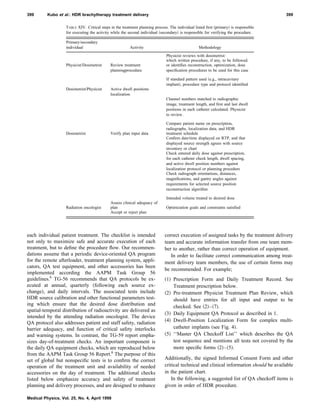
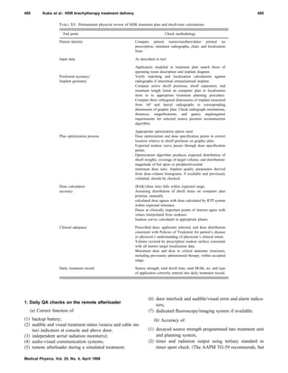


This document provides guidelines for safe delivery of high dose-rate brachytherapy treatments using remote afterloading units. It examines current HDR treatment practices and identifies types of errors. Extensive procedures are outlined for designing an HDR program, including staffing, training, treatment-specific quality assurance, and emergency protocols. Checklists are provided to ensure safety in all aspects of HDR treatment delivery from prescription to post-treatment. The goal is to prevent incidents and assure safe, high-quality HDR brachytherapy care for patients.


