
More Related Content
What's hot
What's hot (20)
Similar to Bomba hidraulica pistones d6 r
Similar to Bomba hidraulica pistones d6 r (20)
Recently uploaded
Recently uploaded (20)
Bomba hidraulica pistones d6 r
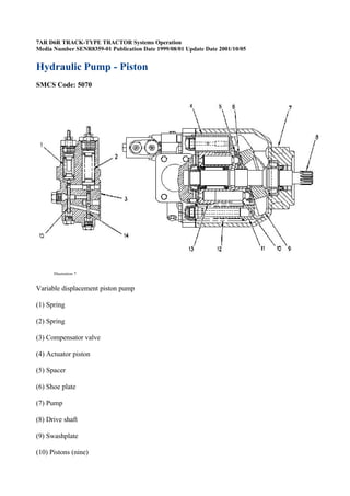
- 1. 7AR D6R TRACK-TYPE TRACTOR Systems Operation Media Number SENR8359-01 Publication Date 1999/08/01 Update Date 2001/10/05 Hydraulic Pump - Piston SMCS Code: 5070 Illustration 7 Variable displacement piston pump (1) Spring (2) Spring (3) Compensator valve (4) Actuator piston (5) Spacer (6) Shoe plate (7) Pump (8) Drive shaft (9) Swashplate (10) Pistons (nine)
- 2. (11) Bias piston (12) Spring (13) Barrel (14) Pressure compensator spool (15) Flow compensator spool The pump for the hydraulic system is an automatically controlled variable displacement axial piston pump. The pump contains two control pistons: bias piston (11) and actuator piston (4). The pump also includes compensator valve (3) in order to limit system pressure. The compensator valve senses both the pressure requirements and the system requirements. While the engine operates, pump drive shaft (8) rotates barrel (13) with nine pistons (10). The ends of the pistons are in the shape of a ball that fits into shoe plate (6). Shoe plate (6) slides on a thin film of oil on swashplate (9). Swashplate (9) does not rotate. Shoe plate (6) is held in place by spacer (5). Note: The swashplate pivots, in order to increase or decrease the swashplate angle. A change in the swashplate angle changes the pump displacement. Pump (7) contains two control pistons: bias piston (11) and actuator piston (4). Bias piston (11) is used in order to upstroke the pump. The bias piston is spring loaded. Also, pump pressure assists the bias piston. Actuator piston (4) is used in order to destroke the pump. Actuator piston (4) has a larger area than the bias piston. Flow compensator spool (15) and/or pressure compensator spool (14) regulates the pressure in actuator piston (4) in order to change the pump displacement. The pressure in actuator piston (4) is supplied by the pump discharge pressure. Compensator valve (3) applies pump pressure to actuator piston (4). The larger actuator piston can override both bias piston (11) and spring (12) in order to destroke the pump. When drive shaft (8) turns barrel (13), pistons (10) move in and out of the barrel as shoe plate (6) follows the angle of the swashplate. As piston (10) moves out of barrel (13), piston (10) draws oil from the hydraulic tank, through the pump inlet, and into the piston cylinder. As the rotation of the barrel continues, the piston moves into the barrel. The piston pushes the oil from the piston cylinder and through the pump outlet. Compensator valve (3) automatically maintains both the pump pressure and the flow in order to fulfill the system requirements. When none of the hydraulic implement circuits are active, the pump is at low pressure standby. Low pressure standby is approximately 2950 kPa (430 psi). However, if one or more circuits are active, a resolver network compares the control valve work port pressures. The highest resolved pressure that is felt flows through a signal line to the pump compensator valve inlet. Then, compensator valve (3) maintains the system requirements. Usually, the actual system pressure is approximately 2100 kPa (305 psi) higher than the highest work port pressure that is required, unless the pump is at full stroke. The difference between the work port requirement and the higher supply pressure is called margin pressure.
- 3. Also, the compensator valve limits pressure in order to prevent overloads of the pump and of the system. When work port pressure rises higher than a set pump pressure of 20000 ± 350 kPa (2900 ± 51 psi), the pressure limiting ability of the compensator overrides the load sensing part of the compensator. Pump output is lowered. This function occurs at approximately 690 kPa (100 psi) lower than the maximum pressure setting. The pressure limiting ability of the compensator protects the hydraulic system from damage by high pressures. The schematics in the next four sections illustrate the actions of the pump and of the compensator valve during different conditions in the hydraulic system. Upstroking Illustration 8 Pump and compensator valve (upstroking) (1) Spring (4) Actuator piston (9) Swashplate (11) Bias piston (12) Spring (15) Flow compensator spool (17) Signal passage
- 4. (18) Pump output passage (19) Case drain passage (20) Passage (21) Passage (22) Passage (23) Passage (24) Cavity (BB) Pressure oil with the first pressure reduction (EE) Signal oil (LL) Tank oil The pump maintains a constant flow up to the cutoff pressure for each system pressure and for each flow demand. (The exception is the maximum displacement position of the swashplate, when the pump output is a function of the engine speed.) Note: Refer to "High Pressure Stall". A need for more hydraulic horsepower (demand) due to an increased circuit load pressure is met by an increased engine torque. (The increased circuit load pressure is not met by a change in the swashplate angle or in the engine speed.) Upstroking occurs when the pump displacement (output) increases. Four conditions can result in upstroking: ·During the initial operation from low pressure standby, the load signal pressure increases pump output for each system demand. See "Low Pressure Standby". ·For each system demand, the pump slightly upstrokes in order to compensate for a built-in pump leakage flow. ·The system demand increases. ·Another hydraulic circuit is activated. Signal pressure flows through signal passage (17) and signal oil fills cavity (24). The signal pressure plus the force of spring (1) moves flow compensator spool (15) downward. (Refer to Illustration 8.) The oil that is behind actuator piston (4) drains past flow compensator spool (15),
- 5. through passage (21), and to case drain passage (19). As the supply oil is momentarily cut off to the actuator piston by flow compensator spool (15), the oil in passage (20) and in bias piston (11) works with spring (12) in order to move the swashplate (9) toward the maximum angle (upstroke). Pump output is increased. The pump output pressure increases until the pressure in passage (22) moves spool (15) up to the metering position. In the metering position, the pump pressure is initially greater than the combined force of spring (1) and of the signal pressure in cavity (24). (Refer to Illustration 7.) Flow compensator spool (15) moves upward. Now, pressure is sent through passage (23) to actuator piston (4). The area of actuator piston (4) is greater than the area of bias piston (11). Therefore, the force that moves swashplate (9) toward the minimum angle (actuator piston) is greater than the force that moves swashplate (9) toward the maximum angle (bias piston plus bias spring). The swashplate angle decreases. Pump output decreases. When the pump pressure decreases enough, the combined signal pressure and spring force in cavity (24) move flow compensator spool (15) downward. (Refer to Illustration 8.) The oil behind actuator piston (4) flows to the case drain. Illustration 9 Typical example of metering spool Bias piston (11) and spring (12) force the angle of swashplate (9) to increase. This up and down spool movement is called metering. Metering keeps the pressure equal on both ends of flow compensator spool (15). Spring (1) is equal to 2100 kPa (305 psi). Therefore, pump pressure is 2100 kPa (305 psi) higher than the signal pressure. The difference is called margin pressure. Destroking
- 6. Illustration 10 Pump and compensator valve (destroking) (1) Spring (4) Actuator piston (9) Swashplate (11) Bias piston (12) Spring (15) Flow compensator spool (17) Signal passage (19) Case drain passage (21) Passage (22) Passage (23) Passage (24) Cavity (AA) High pressure oil
- 7. (DD) Signal oil (LL) Tank oil The pump maintains a constant flow for each system pressure and for each demand. (The exception is the maximum displacement position of the swashplate, when the pump output is a function of the engine speed.) When the demand decreases, the torque on the engine is decreased. (The swashplate angle or the engine speed do not change.) Destroking occurs when the pump displacement (output) decreases. Four conditions can result in destroking: ·The system demand stops. For example, the control valve is moved to the HOLD position. ·The system demand is reduced. ·Any of the operating hydraulic circuits in a multiple circuit operation is in a standby mode or in a reduced flow mode. ·When the highest operating pressure decreases slightly, the built-in pump leakage decreases. The lower signal pressure flows through signal passage (17) and signal oil fills cavity (24). Now, the signal pressure plus the force of spring (1) in cavity (24) is less than the pump pressure in passage (22). Flow compensator spool (15) is pushed upward. Oil behind actuator piston (4) cannot flow through passage (21) to case drain passage (19). Pump oil now flows through passage (22), past flow compensator spool (15), through passage (23), and into actuator piston (4). Pump pressure behind actuator piston (4) is now higher than the combined force of bias piston (11) and spring (12). The angle of swashplate (9) decreases. Pump output decreases until pump output is not sufficient to maintain system pressure. System pressure decreases. When system pressure approaches 2100 kPa (305 psi) (margin pressure) to fulfill a system requirement, flow compensator spool (15) moves downward to the metering position. When all the control valves are in the HOLD position and the system pressure approaches 2950 kPa (430 psi) (low pressure standby), flow compensator spool (15) moves downward to the metering position. The angle of swashplate (9) increases slightly so that pump output compensates for system leakage. Also, the higher swashplate angle maintains the lower required system pressure. While signal pressure remains constant, flow compensator spool (15) stays in the metering position. The hydraulic system is now stabilized. Note: For an explanation of metering, refer to "Upstroking". High Pressure Stall
- 8. Illustration 11 Pump and compensator valve (high pressure stall) (1) Spring (2) Spring (4) Actuator piston (9) Swashplate (14) Pressure compensator spool (15) Flow compensator spool (17) Signal passage (22) Passage (23) Passage (24) Cavity (AA) High pressure oil (EE) Signal oil (LL) Tank oil
- 9. A high pressure stall occurs when the hydraulic system stalls under a load or the cylinders reach the end of the stroke. A stall occurs when pump output reaches 20000 kPa (2900 psi). The signal pressure in signal passage (17) and in cavity (24) now equals the pump output pressure. Spring (1) keeps flow compensator spool (15) moved downward. When the system pressure reaches 20000 kPa (2900 psi) in passage (22), the force on pressure compensator spool (14) compresses spring (2). Pressure compensator spool (14) moves upward. Supply oil flows through passage (23) to actuator piston (4). The pressure that is felt on the actuator piston destrokes the pump. Pump output decreases while the system pressure stays at 20000 kPa (2900 psi). If the control lever is moved to the HOLD position during a high pressure stall, the signal pressure in cavity (24) flows back through signal passage (17), through the resolver network, and to the control valve. Then, the signal oil returns to the tank. The system pressure decreases. At approximately 19650 kPa (2850 psi), spring (2) moves pressure compensator spool (14) downward. The system pressure in passage (22) acts against the force of spring (1) in order to move flow compensator spool (15) upward. The supply oil flows past flow compensator spool (15), past pressure compensator spool (14), through passage (23), and to actuator piston (4). Actuator piston (4) decreases the angle of swashplate (9) until the system pressure decreases. As system pressure decreases, flow compensator spool (15) moves downward to the metering position. Swashplate (9) maintains a slight angle in order to compensate for system leakage. Also, the swashplate angle provides the lower required pressure. Pump output is maintained at about 2950 kPa (430 psi). This condition is called low pressure standby. Low Pressure Standby
- 10. Illustration 12 Pump and compensator valve (low pressure standby) (1) Spring (4) Actuator piston (9) Swashplate (11) Bias piston (12) Spring (14) Pressure compensator spool (15) Flow compensator spool (17) Signal passage (22) Passage (23) Passage (24) Cavity (25) Cross-drilled hole (BB) Pressure oil with the first pressure reduction (LL) Tank oil A low pressure standby occurs while the engine operates with the control levers in the HOLD. The demand on the pump is zero. Therefore, the signal pressure in signal passage (17) is zero. Before the engine is started, bias spring (12) maintains swashplate (9) at the maximum angle. As the pump turns,the closed centered implement valve builds up pressure in the system. The pressure in passage (22) is transmitted to the bottom of both pressure compensator spool (14) (pressure limiter) and flow compensator spool (15). As the pressure increases, the pressure pushes the flow compensator spool against spring (1). When system pressure is higher than 2950 kPa (430 psi), flow compensator spool (15) moves upward. Flow compensator spool (15) moves sufficiently in order to open a passage for pressure oil to the back of actuator piston (4). The actuator piston moves to the right. Bias spring (12) is compressed. The swashplate moves toward the minimum angle. The actuator piston continues to move to the right until the actuator piston uncovers cross- drilled passage (25) of the actuator piston rod. Oil drains to the case. Pump output is not sufficient to compensate for normal system leakage. The additional leakage through cross-drilled hole (25) decreases the oil pressure behind the actuator piston. The decrease in the oil pressure limits the movement of the piston. Now, the piston moves slightly to the left until only a part of cross-drilled hole (25) is open to the case. The pump produces sufficient flow in order to compensate for system leakage and for leakage to the pump case through the cross-drilled hole. Also, this pump flow is sufficient to maintain system pressure at 2950 kPa (420 psi).
- 11. The pump is at low pressure standby. This pressure is different from margin pressure due to system leakage and due to cross-drilled hole (25) in the actuator piston rod. The flow compensator spool does not meter the oil. Instead, the flow compensator spool remains open. The spool moves upward against spring (1). Oil flows to the back side of the actuator piston in order to compensate for leakage through the cross-drilled hole. The flow maintains the pressure that is required at the back of the piston in order to overcome the bias spring. System pressure must be 1230 kPa (180 psi) higher than the margin pressure in order to move the spool upward against spring (1). Oil pressure behind the actuator piston is lower than system pressure due to the pressure drop across the flow compensator spool. Note: Low pressure standby is not adjustable. Low pressure standby varies between different machines. Also, low pressure standby varies in the same pump with an increase in system leakage or in pump leakage. As leakage increases, the pump upstrokes slightly in order to compensate for leakage. The actuator piston covers more of the cross-drilled hole. Low pressure standby drops toward margin pressure. When the actuator piston completely covers the cross-drilled hole, low pressure standby equals margin pressure. Copyright 1991, 2003 Caterpillar Inc. All Rights Reserved.