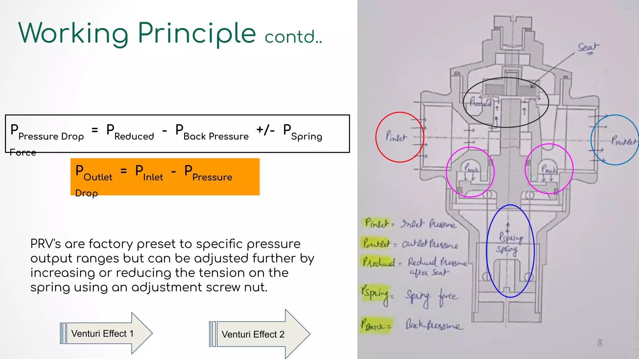
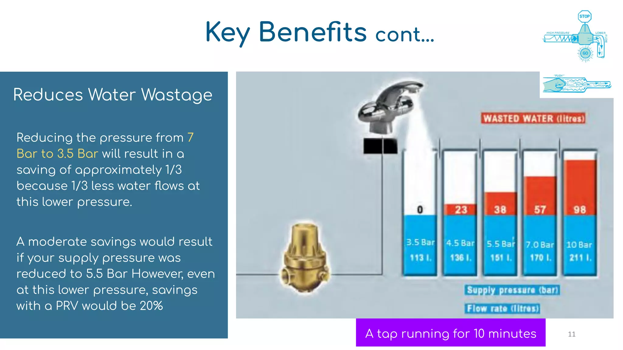
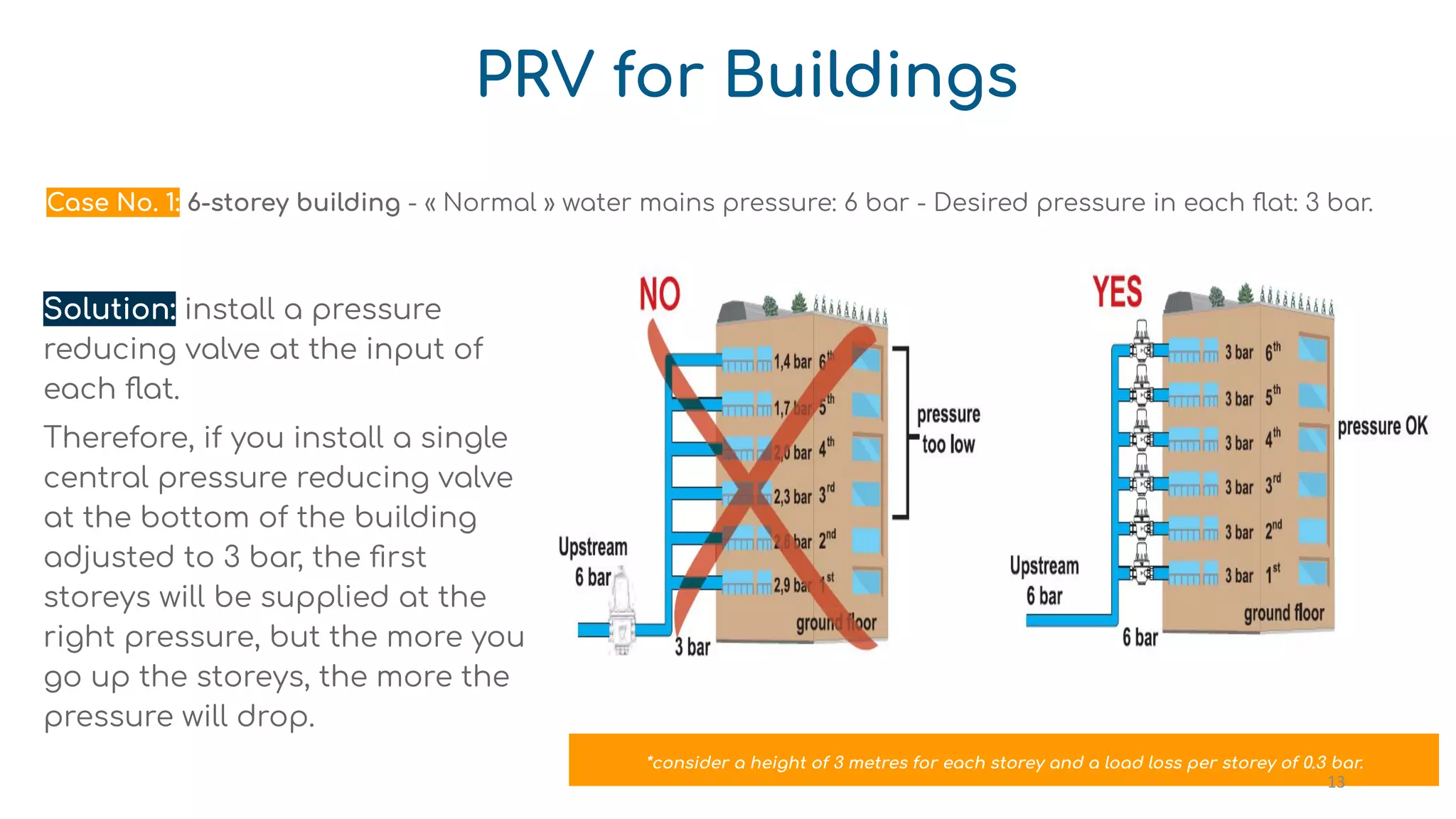
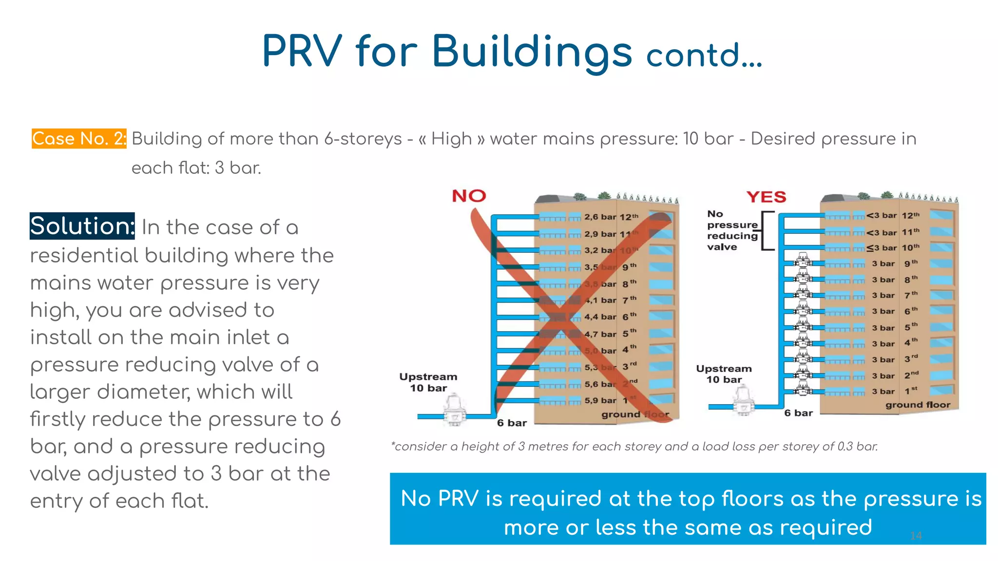
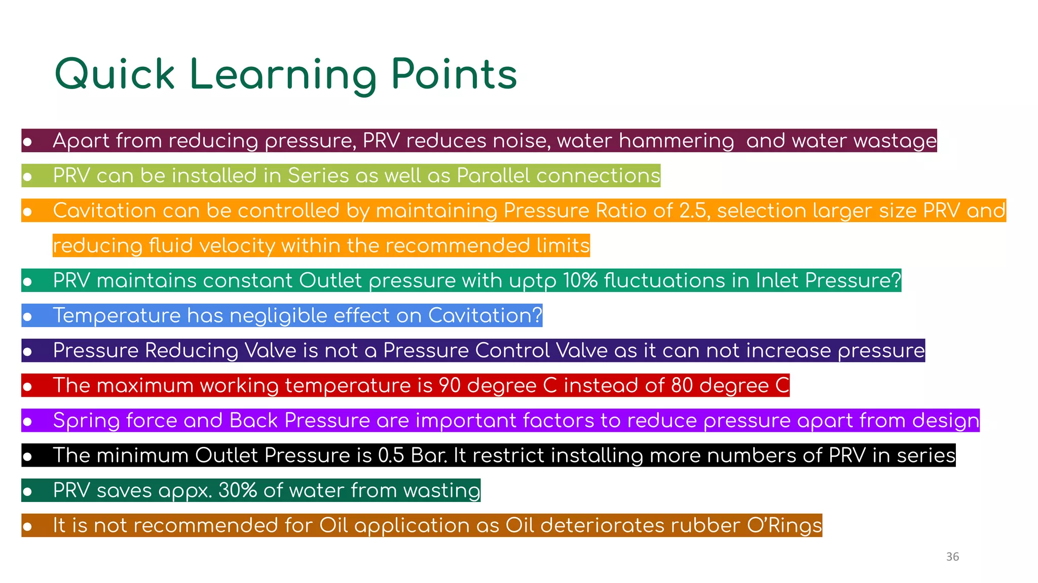
SlideShare a Scribd company logo
Pressure
Reducing
Valve
1
Do You Think?
● Reducing Pressure is the only output of a Pressure Reducing Valve?
● Pressure Reducing Valves are installed in Series, only?
● Cavitation can be avoided only by maintaining Pressure Ratio of 2.5?
● PRV maintains constant Outlet pressure with fluctuations in Inlet Pressure?
● Temperature has no effect on Cavitation?
● Pressure Reducing Valve is a Pressure Control Valve?
● The maximum working temperature is 80 degree C
● Spring force is the only factor behind reducing the pressure?
● Unlimited numbers of PRV can be installed in Series?
● PRV reduces water hammering and noise in the pipeline?
● PRV saves lot of water from wasting?
● It is not recommended for Oil application?
2
Pressure Reducing Valve (PRV)
PRV is a device used for reducing the
pressure of water in the pipeline to the
desired level at its actual point of use and
thereafter, regulating it continually, on its
own.
Uses:
● To keep the pressure of the water constant in
the distribution network
● To avoid excessive wastage of water
● To keep the water pressure constantly below
the maximum value allowed
First Pressure Reducing Valve was developed in the
year 1876 by Watt Industries 3
Types of PRV
1. Direct Acting
○ Piston type
○ Diaphragm type
2. Pilot-Operated
○ Internally Pilot-Piston Operated
○ Externally Pilot Operated
4
Types of PRV contd..
Direct Acting Pilot Operated 5
6
Types of PRV contd..
Direct Acting PRV
Used for small loads where extremely close
pressure control is not needed.
● Pros: Compact size, low price, easy to
install.
● Cons: Higher droop (variation from set
pressure) than Pilot-operated PRV
Direct-operated valves are used when loads are
small and some downstream pressure
variations may be accepted. They are generally
used in light load services
Pilot Operated PRV
Used for larger loads where close pressure
control is required
● Pros: Close pressure control, fast response
to load variation, may be used across a
broader range of flow rates than the direct
acting types.
● Cons: Larger size, higher price.
Pilot-operated pressure reducing valves can
respond quickly to varying load conditions
while maintaining stable secondary pressure
where precise pressure control is needed. They
are generally intended for larger load
applications.
Working Principle
Piston Type PRV is based upon principle of Venturi Effect
and Equilibrium of Forces.
There are three forces acting on the fluid (water) between
the Inlet and the Outlet Ports. These Forces are:
1. Reduced Pressure (after Seat),
2. Back Pressure (acting on the underside of the piston)
3. Spring Force
Three Steps are involved:
● Pressure is reduced due to reduction in the cross
sectional area (bore) and amount of opening of the disc
(higher the opening higher the Outlet Pressure)
● Back Pressure tends to close the seat
● Spring Force which tends to open/close the Seat w.r.t
Pre-Set condition
7
Working Principle contd..
PRV's are factory preset to specific pressure
output ranges but can be adjusted further by
increasing or reducing the tension on the
spring using an adjustment screw nut.
PPressure Drop
= PReduced
- PBack Pressure
+/- PSpring
Force
POutlet
= PInlet
- PPressure
Drop
Venturi Effect 2
8
Venturi Effect 1
Key Benefits
Maintains Constant
Downstream Pressure at
desired level
Reduces Water Wastage
Reduces Water Hammering
and Noise
Reduces Maintenance Cost
Saves Energy. Saves Money
9
Facility provided to install
pressure gauge
Single Valve for wide range of
pressure (25 Bar max Inlet to 0.5 Bar
min outlet
Easy to install
Requires less maintenance
Noiseless
Salient Features of Piston Type PRV
Piston Operated, having long life as
piston is of forged brass
Needs less space to install
Easy Pressure setting
Cost Economic
Rugged body, compact in design
Most of the critical working components
have a distinct edge of being hot brass
forged
All 'O' rings of superior food grade
material, hence ensuring absolute
zero health hazard
Suitable only for water application, due to Rubber O’Rings, limited range of temperature and chemical reactivity (Oil etc)
10
Key Benefits cont...
Reduces Water Wastage
Reducing the pressure from 7
Bar to 3.5 Bar will result in a
saving of approximately 1/3
because 1/3 less water flows at
this lower pressure.
A moderate savings would result
if your supply pressure was
reduced to 5.5 Bar However, even
at this lower pressure, savings
with a PRV would be 20%
A tap running for 10 minutes 11
Key Benefits cont...
Reduces Water
Hammering & Noise
The abrupt stoppage of high speed
water causes a “bounceback” of the
water and is called Water Hammer,
causing banging pipes, noisy systems
and damage to appliance.
Using a PRV can control the water
hammering effect and reduces the
maintenance & replacement cost.
PRV reduces maintenance cost of piping and fittings
Water Hammering
12
PRV for Buildings
Solution: install a pressure
reducing valve at the input of
each flat.
Therefore, if you install a single
central pressure reducing valve
at the bottom of the building
adjusted to 3 bar, the first
storeys will be supplied at the
right pressure, but the more you
go up the storeys, the more the
pressure will drop.
*consider a height of 3 metres for each storey and a load loss per storey of 0.3 bar.
Case No. 1: 6-storey building - « Normal » water mains pressure: 6 bar - Desired pressure in each flat: 3 bar.
13
PRV for Buildings contd...
Solution: In the case of a
residential building where the
mains water pressure is very
high, you are advised to
install on the main inlet a
pressure reducing valve of a
larger diameter, which will
firstly reduce the pressure to 6
bar, and a pressure reducing
valve adjusted to 3 bar at the
entry of each flat.
*consider a height of 3 metres for each storey and a load loss per storey of 0.3 bar.
No PRV is required at the top floors as the pressure is
more or less the same as required
Case No. 2: Building of more than 6-storeys - « High » water mains pressure: 10 bar - Desired pressure in
each flat: 3 bar.
14
PRV for Buildings contd...
In this case, the installation of a
pressure booster is necessary.
This will be adjusted to a value
of 5 or 6 bar, the purpose being
to obtain adequate pressure at
all floors. It is therefore
necessary to install the same
pressure reducing valve,
adjusted to 3 bar, at the entry
of each flat.
For very high buildings, the highest storeys do not require the installation of a pressure reducing valve
when the pressure is less than 3 bar.
Case No. 3: Building of more than 6-storeys - « Low » water mains pressure: 3 bar. Desired pressure in each
flat: 3 bar.
15
16
PRV for Buildings contd...
Case No. 4: Water Supply from the Overhead Tank
Cavitation
If the differential of pressure between the upstream
and the desired downstream is too large, then it will
be necessary to reduce the pressure in several
stages by installing a series of pressure reducing
valves. A high inlet pressure and a low downstream
pressure can cause a deterioration of the valve by
Cavitation.
In simple words Cavitation is a phase that is
characterized by a liquid-vapour-liquid process, all
contained within a small area of the valve and within
microseconds. Minor cavitation damage may be
considered normal for some applications, which can
be dealt with during routine maintenance. If
unnoticed or unattended, severe cavitation can limit
the life expectancy of the valve. Temperature has
almost no effect on Cavitation Cavitation
17
18
The cavitation diagram shows the three operating
zones of the pressure reducing valve in function to
the inlet and outlet pressures:
ZONE 1: Cavitation Zone: The cavitation phenomena
is clearly evident in this zone. It is recommended to
refrain from using pressure reducing valve under
such pressure differential conditions.
ZONE 2: Critical Zone: The possible occurrence of
cavitation phenomena inside the pressure reducing
valve is evidenced. It is recommended to avoid using
the pressure reducing valve at these pressures
differential conditions.
ZONE 3: Safe operating zone: Here the pressure reducing valve operates in optimum conditions
and there is no cavitation in this Zone. This is the optimum interval of pressure values for the
operation of the pressure reducing valve.
Cavitation Diagram
19
Selection of PRV (A Typical Example)
PRV in Series
For Example:
Inlet Pressure = 13 Bar
Outlet Pressure = 3 Bar
It falls in Cavitation Zone (as depicted in Cavitation Diagram)
Solution: Use two PRV’s in series to achieve the desired
pressure differential.
PRV - 1
Inlet Pressure = 13 Bar
Outlet Pressure = 6 Bar (pressure ratio: 13/6 = 2.17 < 2.5)
PRV - 2
Inlet Pressure = 6 Bar
Outlet Pressure = 3 Bar (pressure ratio: 6/3 = 2.0 < 2.5) 20
Installing PRV’s in Parallel connection
Parallel installation is
recommended for
applications with a wide
variation of reduced
pressure requirements and
where a continuous water
supply must be
maintained. Parallel
installations offer the
advantage of providing
increased capacity beyond
that provided by a single
valve and improve valve
performance for widely
variable demands.
Parallel Connection with Smaller Size
Valves or Same Size Valves
21
Size and type of pipe
Maximum inlet pressure
Minimum required downstream pressure
“While selecting a PRV, the pipe size alone is not necessarily the determining factor.
The above factors must be considered”
Pressure Reducing
Valve (PRV)
Selection
Water demand in amount (e.g. LPM)
22
PRV Installation
Zoloto pressure reducing valves may be installed in any positions.
❏ Horizontal
❏ Vertical
❏ Bottom side up
❏ Inclined
Generally installed in high rise buildings at inlet of each floor 23
Pressure Setting of PRV
24
● Install the PRV on the pipe as shown in the layout diagram
and open the cap (part no. 14)
● Release the adjusting ring by rotating it, anti-clockwise with
the help of a screwdriver so that the PRV comes in fully closed
position.
● Set the inlet pressure you want to feed into the PRV and check
the same on Pressure Gauge-1
● In order to adjust the outlet pressure, close the valve ‘Y' and
open the valve 'X'. Now turn the adjusting ring (part no. 13) in
clockwise direction slowly until you see the needle of pressure
gauge-2 showing a rise in pressure & stop rotating it just
before the desired outlet pressure is attained.
● Now open the valve 'Y' to release the pressure once and close
it again.
Pressure Setting of PRV contd..
25
Pressure Setting of PRV contd..
● Watch the Pressure Gauge-2. The needle of the gauge should point to the set
pressure, if there is any deviation+/_ please adjust the same by moving the
adjusting ring accordingly in clockwise or anticlockwise direction, until the desired
pressure is achieved.
● Please remember that the rotational movement of adjusting ring in clockwise
direction increase the outlet pressure and anticlockwise direction decreases the
same, on the outlet side.
● When the outlet pressure is adjusted to the desired level, please close the cap
(part no. 14)
● Plug-1 is only a cover to protect the thread provided for installation of 1/4" BSP
sized pressure gauge.
26
Precautions
❏ Although Pressure reducing valves needs no maintenance but
the rubber “O” rings inside the PRV are very sensitive to scale,
impurities, or any foreign particles so it's always recommended
to flush the line thoroughly and install a strainer in the main
line.
❏ In the case of a residential building, it is advisable to install a
pressure reducing valve at the input of each flat, and not a
centralized pressure reducing valve at the bottom of the
building.
27
Troubles in PRV
● Foreign particles (sand, dust, welding splinters) accumulated inside PRV which
damaged the 'o' ring.
● PRV installed in reverse direction of arrow marked.
● Strainer is not provided before the PRV.
● Too much variation in inlet pressure.
● User not aware about that how to set the pressure.
● Bye pass line not provided.
● Lack of knowledge for inlet pressure.
● PRV installed in such a position i.e very near to the wall, where it cannot be
serviced.
28
Troubleshooting
29
● Flush the pipe lines before installing the PRV
○ This is recommended to avoid the foreign particles / dust passing through the PRV.
These particles obstruct the PRV’s smooth functioning causing damage/blockage
of the seating surface.
● Install a strainer in the main line before the PRV
○ The strainer serves to filter out the dust and dirt particles from the pipeline and
ensures smooth operation of PRV's.
Troubleshooting contd..
30
Correct Sizing of PRV
In order to avoid cavitation phenomena, it is recommend to:
❖ Utilize the “CAVITATION DIAGRAM”
➢ This diagram helps to understand about Cavitation Zones and to select the
correct size of the valve
❖ Use correct Pressure Ratio
➢ The ratio between the maximum inlet pressure and the regulated pressure
should not be more than 2.5
❖ Install more numbers of Pressure Reducing Valves
➢ To achieve the desired pressure differential, use more numbers of pressure
reducing valves in series or parallel connections
❖ Choose Optimum Speed value of the Fluid
➢ Select the diameter of the PRV (valve size) so that speed (velocity) of the fluid
passing through it is between the recommended values (V= 0.7 - 1.5 m/s for residential
use and V= 1 - 3.5 m/s for industrial use)
31
Pressure Drop vs Flow Rate
For Example:
Inlet Pressure: 4.8 Bar
Outlet Pressure: 3.0 Bar
Size of PRV: 40 mm (1½”)
Pressure Drop (Head Loss) =
Inlet Pressure - Outlet Pressure
= 4.8 - 3.0 = 1.8 Bar
Flow Rate (Discharge) will be 3.1 Litre per sec (186 LPM) as calculated from the above diagram
32
Maintenance
Video
PRV Pressure
Setting Video
PRV Videos
Pressure Reducing Valve
33
PRV Pressure Setting
34
35
Quick Learning Points
● Apart from reducing pressure, PRV reduces noise, water hammering and water wastage
● PRV can be installed in Series as well as Parallel connections
● Cavitation can be controlled by maintaining Pressure Ratio of 2.5, selection larger size PRV and
reducing fluid velocity within the recommended limits
● PRV maintains constant Outlet pressure with uptp 10% fluctuations in Inlet Pressure?
● Temperature has negligible effect on Cavitation?
● Pressure Reducing Valve is not a Pressure Control Valve as it can not increase pressure
● The maximum working temperature is 90 degree C instead of 80 degree C
● Spring force and Back Pressure are important factors to reduce pressure apart from design
● The minimum Outlet Pressure is 0.5 Bar. It restrict installing more numbers of PRV in series
● PRV saves appx. 30% of water from wasting
● It is not recommended for Oil application as Oil deteriorates rubber O’Rings
36
Thank You!
any question, please
37

More Related Content

What's hot

Different types of control valves
Different types of control valvesDifferent types of control valves
Different types of control valves
Prem Baboo
 
Fundamental of hydraulics
Fundamental of hydraulicsFundamental of hydraulics
Fundamental of hydraulics
Ganesh Murugan
 
Control valve presentation
Control valve presentationControl valve presentation
Control valve presentation
Prem kumar
 
Flow meter
Flow meterFlow meter
pumps and its types-ppt
pumps and its types-pptpumps and its types-ppt
pumps and its types-ppt
Dharmas India
 
Valves presentation
Valves presentationValves presentation
Valves presentation
mohdalaamri
 
Venturi
VenturiVenturi
Safety valves
Safety valvesSafety valves
Safety valves
Gaurav Kaushik
 
Valves
ValvesValves
Air Compressor
Air CompressorAir Compressor
Air Compressor
Parth Patel
 
Valves
ValvesValves
Pump, its types and applications presentation
Pump, its types and applications presentationPump, its types and applications presentation
Pump, its types and applications presentation
ziaul islam
 
Actuator and valves
Actuator and valvesActuator and valves
Actuator and valves
Dhruv Upadhaya
 
Control valves
Control valves Control valves
Control valves
Sadiq Rahim
 
Steam jet ejectors
Steam jet ejectorsSteam jet ejectors
Steam jet ejectors
shehzad hussain
 
Accumulators
AccumulatorsAccumulators
Accumulators
srinivaspp
 
Psv scenario-and-calculation
Psv scenario-and-calculationPsv scenario-and-calculation
Psv scenario-and-calculation
ChingLuh Nike
 
Pumps and Cavitation
Pumps and CavitationPumps and Cavitation
Pumps and Cavitation
Living Online
 
CAVITATION IN CENTRIFUGAL PUMP
CAVITATION IN CENTRIFUGAL PUMPCAVITATION IN CENTRIFUGAL PUMP
CAVITATION IN CENTRIFUGAL PUMP
DEBJYOTI MONDAL
 
Control valve ppt
Control valve pptControl valve ppt
Control valve ppt
Tarit Mahata
 

What's hot (20)

Different types of control valves
Different types of control valvesDifferent types of control valves
Different types of control valves
 
Fundamental of hydraulics
Fundamental of hydraulicsFundamental of hydraulics
Fundamental of hydraulics
 
Control valve presentation
Control valve presentationControl valve presentation
Control valve presentation
 
Flow meter
Flow meterFlow meter
Flow meter
 
pumps and its types-ppt
pumps and its types-pptpumps and its types-ppt
pumps and its types-ppt
 
Valves presentation
Valves presentationValves presentation
Valves presentation
 
Venturi
VenturiVenturi
Venturi
 
Safety valves
Safety valvesSafety valves
Safety valves
 
Valves
ValvesValves
Valves
 
Air Compressor
Air CompressorAir Compressor
Air Compressor
 
Valves
ValvesValves
Valves
 
Pump, its types and applications presentation
Pump, its types and applications presentationPump, its types and applications presentation
Pump, its types and applications presentation
 
Actuator and valves
Actuator and valvesActuator and valves
Actuator and valves
 
Control valves
Control valves Control valves
Control valves
 
Steam jet ejectors
Steam jet ejectorsSteam jet ejectors
Steam jet ejectors
 
Accumulators
AccumulatorsAccumulators
Accumulators
 
Psv scenario-and-calculation
Psv scenario-and-calculationPsv scenario-and-calculation
Psv scenario-and-calculation
 
Pumps and Cavitation
Pumps and CavitationPumps and Cavitation
Pumps and Cavitation
 
CAVITATION IN CENTRIFUGAL PUMP
CAVITATION IN CENTRIFUGAL PUMPCAVITATION IN CENTRIFUGAL PUMP
CAVITATION IN CENTRIFUGAL PUMP
 
Control valve ppt
Control valve pptControl valve ppt
Control valve ppt
 

Similar to Pressure Reducing Valve (PRV) - Part1

Automatic Recirculation Valve
Automatic Recirculation ValveAutomatic Recirculation Valve
Automatic Recirculation Valve
Ahmed Abd ElKader
 
Designer and operator manual dorot
Designer and operator manual dorotDesigner and operator manual dorot
Designer and operator manual dorot
Carlos Rovello
 
Designer and operator manual dorot
Designer and operator manual dorotDesigner and operator manual dorot
Designer and operator manual dorot
Carlos Rovello
 
Application guide
Application guideApplication guide
Application guide
Edward Valera
 
Pressure Reliveing Devices1
Pressure Reliveing Devices1Pressure Reliveing Devices1
Pressure Reliveing Devices1
Om Pratap Singh
 
Model 8.1-pressure control
Model 8.1-pressure controlModel 8.1-pressure control
Model 8.1-pressure control
KrishnaPATEL36202
 
Boiler doc 08 control application
Boiler doc 08   control applicationBoiler doc 08   control application
Boiler doc 08 control application
Mars Tsani
 
FUNDAMENTAL OF VALVE DESIGN
FUNDAMENTAL OF VALVE DESIGN FUNDAMENTAL OF VALVE DESIGN
FUNDAMENTAL OF VALVE DESIGN
MOHAMMAD ATIF ALI
 
Backflow Preventers
Backflow PreventersBackflow Preventers
Backflow Preventers
sherylwil
 
General Control Valve Study
General Control Valve StudyGeneral Control Valve Study
General Control Valve Study
Dnyaneshwar Gavhane
 
Harga ariston 082113812149
Harga ariston 082113812149Harga ariston 082113812149
Harga ariston 082113812149
Harga Water Heater Ariston 082113812149
 
ADR PRV Presentation.pptx
ADR PRV Presentation.pptxADR PRV Presentation.pptx
ADR PRV Presentation.pptx
Raja Sv
 
Pump principles
Pump principlesPump principles
Pump principles
Yuri Melliza
 
air evacuation system and lrpv (liquid ring vacuum pump)
air evacuation system and lrpv (liquid ring vacuum pump) air evacuation system and lrpv (liquid ring vacuum pump)
air evacuation system and lrpv (liquid ring vacuum pump)
Rhitesh Gupta
 
vivasat ventures flow division
vivasat ventures flow divisionvivasat ventures flow division
vivasat ventures flow division
Heena Agarwal
 
Cold Water Supply Distribution In Building
Cold Water Supply Distribution In BuildingCold Water Supply Distribution In Building
Cold Water Supply Distribution In Building
Van Heina
 
Control Valves
Control ValvesControl Valves
Control Valves
Shivam Singh
 
Valve type-modi-11
Valve type-modi-11Valve type-modi-11
Valve type-modi-11
Valve type-modi-11Valve type-modi-11
FINEKAY™ PRESSURE VACUUM RELIEF VALVE GUIDE
FINEKAY™ PRESSURE VACUUM RELIEF VALVE GUIDEFINEKAY™ PRESSURE VACUUM RELIEF VALVE GUIDE
FINEKAY™ PRESSURE VACUUM RELIEF VALVE GUIDE
志强 李
 

Similar to Pressure Reducing Valve (PRV) - Part1 (20)

Automatic Recirculation Valve
Automatic Recirculation ValveAutomatic Recirculation Valve
Automatic Recirculation Valve
 
Designer and operator manual dorot
Designer and operator manual dorotDesigner and operator manual dorot
Designer and operator manual dorot
 
Designer and operator manual dorot
Designer and operator manual dorotDesigner and operator manual dorot
Designer and operator manual dorot
 
Application guide
Application guideApplication guide
Application guide
 
Pressure Reliveing Devices1
Pressure Reliveing Devices1Pressure Reliveing Devices1
Pressure Reliveing Devices1
 
Model 8.1-pressure control
Model 8.1-pressure controlModel 8.1-pressure control
Model 8.1-pressure control
 
Boiler doc 08 control application
Boiler doc 08   control applicationBoiler doc 08   control application
Boiler doc 08 control application
 
FUNDAMENTAL OF VALVE DESIGN
FUNDAMENTAL OF VALVE DESIGN FUNDAMENTAL OF VALVE DESIGN
FUNDAMENTAL OF VALVE DESIGN
 
Backflow Preventers
Backflow PreventersBackflow Preventers
Backflow Preventers
 
General Control Valve Study
General Control Valve StudyGeneral Control Valve Study
General Control Valve Study
 
Harga ariston 082113812149
Harga ariston 082113812149Harga ariston 082113812149
Harga ariston 082113812149
 
ADR PRV Presentation.pptx
ADR PRV Presentation.pptxADR PRV Presentation.pptx
ADR PRV Presentation.pptx
 
Pump principles
Pump principlesPump principles
Pump principles
 
air evacuation system and lrpv (liquid ring vacuum pump)
air evacuation system and lrpv (liquid ring vacuum pump) air evacuation system and lrpv (liquid ring vacuum pump)
air evacuation system and lrpv (liquid ring vacuum pump)
 
vivasat ventures flow division
vivasat ventures flow divisionvivasat ventures flow division
vivasat ventures flow division
 
Cold Water Supply Distribution In Building
Cold Water Supply Distribution In BuildingCold Water Supply Distribution In Building
Cold Water Supply Distribution In Building
 
Control Valves
Control ValvesControl Valves
Control Valves
 
Valve type-modi-11
Valve type-modi-11Valve type-modi-11
Valve type-modi-11
 
Valve type-modi-11
Valve type-modi-11Valve type-modi-11
Valve type-modi-11
 
FINEKAY™ PRESSURE VACUUM RELIEF VALVE GUIDE
FINEKAY™ PRESSURE VACUUM RELIEF VALVE GUIDEFINEKAY™ PRESSURE VACUUM RELIEF VALVE GUIDE
FINEKAY™ PRESSURE VACUUM RELIEF VALVE GUIDE
 

Recently uploaded

Modelagem de um CSTR com reação endotermica.pdf
Modelagem de um CSTR com reação endotermica.pdfModelagem de um CSTR com reação endotermica.pdf
Modelagem de um CSTR com reação endotermica.pdf
camseq
 
Recycled Concrete Aggregate in Construction Part III
Recycled Concrete Aggregate in Construction Part IIIRecycled Concrete Aggregate in Construction Part III
Recycled Concrete Aggregate in Construction Part III
Aditya Rajan Patra
 
Question paper of renewable energy sources
Question paper of renewable energy sourcesQuestion paper of renewable energy sources
Question paper of renewable energy sources
mahammadsalmanmech
 
Computational Engineering IITH Presentation
Computational Engineering IITH PresentationComputational Engineering IITH Presentation
Computational Engineering IITH Presentation
co23btech11018
 
Optimizing Gradle Builds - Gradle DPE Tour Berlin 2024
Optimizing Gradle Builds - Gradle DPE Tour Berlin 2024Optimizing Gradle Builds - Gradle DPE Tour Berlin 2024
Optimizing Gradle Builds - Gradle DPE Tour Berlin 2024
Sinan KOZAK
 
CSM Cloud Service Management Presentarion
CSM Cloud Service Management PresentarionCSM Cloud Service Management Presentarion
CSM Cloud Service Management Presentarion
rpskprasana
 
Harnessing WebAssembly for Real-time Stateless Streaming Pipelines
Harnessing WebAssembly for Real-time Stateless Streaming PipelinesHarnessing WebAssembly for Real-time Stateless Streaming Pipelines
Harnessing WebAssembly for Real-time Stateless Streaming Pipelines
Christina Lin
 
Iron and Steel Technology Roadmap - Towards more sustainable steelmaking.pdf
Iron and Steel Technology Roadmap - Towards more sustainable steelmaking.pdfIron and Steel Technology Roadmap - Towards more sustainable steelmaking.pdf
Iron and Steel Technology Roadmap - Towards more sustainable steelmaking.pdf
RadiNasr
 
Heat Resistant Concrete Presentation ppt
Heat Resistant Concrete Presentation pptHeat Resistant Concrete Presentation ppt
Heat Resistant Concrete Presentation ppt
mamunhossenbd75
 
Generative AI leverages algorithms to create various forms of content
Generative AI leverages algorithms to create various forms of contentGenerative AI leverages algorithms to create various forms of content
Generative AI leverages algorithms to create various forms of content
Hitesh Mohapatra
 
Manufacturing Process of molasses based distillery ppt.pptx
Manufacturing Process of molasses based distillery ppt.pptxManufacturing Process of molasses based distillery ppt.pptx
Manufacturing Process of molasses based distillery ppt.pptx
Madan Karki
 
ACEP Magazine edition 4th launched on 05.06.2024
ACEP Magazine edition 4th launched on 05.06.2024ACEP Magazine edition 4th launched on 05.06.2024
ACEP Magazine edition 4th launched on 05.06.2024
Rahul
 
Recycled Concrete Aggregate in Construction Part II
Recycled Concrete Aggregate in Construction Part IIRecycled Concrete Aggregate in Construction Part II
Recycled Concrete Aggregate in Construction Part II
Aditya Rajan Patra
 
Properties Railway Sleepers and Test.pptx
Properties Railway Sleepers and Test.pptxProperties Railway Sleepers and Test.pptx
Properties Railway Sleepers and Test.pptx
MDSABBIROJJAMANPAYEL
 
TIME DIVISION MULTIPLEXING TECHNIQUE FOR COMMUNICATION SYSTEM
TIME DIVISION MULTIPLEXING TECHNIQUE FOR COMMUNICATION SYSTEMTIME DIVISION MULTIPLEXING TECHNIQUE FOR COMMUNICATION SYSTEM
TIME DIVISION MULTIPLEXING TECHNIQUE FOR COMMUNICATION SYSTEM
HODECEDSIET
 
CHINA’S GEO-ECONOMIC OUTREACH IN CENTRAL ASIAN COUNTRIES AND FUTURE PROSPECT
CHINA’S GEO-ECONOMIC OUTREACH IN CENTRAL ASIAN COUNTRIES AND FUTURE PROSPECTCHINA’S GEO-ECONOMIC OUTREACH IN CENTRAL ASIAN COUNTRIES AND FUTURE PROSPECT
CHINA’S GEO-ECONOMIC OUTREACH IN CENTRAL ASIAN COUNTRIES AND FUTURE PROSPECT
jpsjournal1
 
Engineering Drawings Lecture Detail Drawings 2014.pdf
Engineering Drawings Lecture Detail Drawings 2014.pdfEngineering Drawings Lecture Detail Drawings 2014.pdf
Engineering Drawings Lecture Detail Drawings 2014.pdf
abbyasa1014
 
basic-wireline-operations-course-mahmoud-f-radwan.pdf
basic-wireline-operations-course-mahmoud-f-radwan.pdfbasic-wireline-operations-course-mahmoud-f-radwan.pdf
basic-wireline-operations-course-mahmoud-f-radwan.pdf
NidhalKahouli2
 
ISPM 15 Heat Treated Wood Stamps and why your shipping must have one
ISPM 15 Heat Treated Wood Stamps and why your shipping must have oneISPM 15 Heat Treated Wood Stamps and why your shipping must have one
ISPM 15 Heat Treated Wood Stamps and why your shipping must have one
Las Vegas Warehouse
 
Textile Chemical Processing and Dyeing.pdf
Textile Chemical Processing and Dyeing.pdfTextile Chemical Processing and Dyeing.pdf
Textile Chemical Processing and Dyeing.pdf
NazakatAliKhoso2
 

Recently uploaded (20)

Modelagem de um CSTR com reação endotermica.pdf
Modelagem de um CSTR com reação endotermica.pdfModelagem de um CSTR com reação endotermica.pdf
Modelagem de um CSTR com reação endotermica.pdf
 
Recycled Concrete Aggregate in Construction Part III
Recycled Concrete Aggregate in Construction Part IIIRecycled Concrete Aggregate in Construction Part III
Recycled Concrete Aggregate in Construction Part III
 
Question paper of renewable energy sources
Question paper of renewable energy sourcesQuestion paper of renewable energy sources
Question paper of renewable energy sources
 
Computational Engineering IITH Presentation
Computational Engineering IITH PresentationComputational Engineering IITH Presentation
Computational Engineering IITH Presentation
 
Optimizing Gradle Builds - Gradle DPE Tour Berlin 2024
Optimizing Gradle Builds - Gradle DPE Tour Berlin 2024Optimizing Gradle Builds - Gradle DPE Tour Berlin 2024
Optimizing Gradle Builds - Gradle DPE Tour Berlin 2024
 
CSM Cloud Service Management Presentarion
CSM Cloud Service Management PresentarionCSM Cloud Service Management Presentarion
CSM Cloud Service Management Presentarion
 
Harnessing WebAssembly for Real-time Stateless Streaming Pipelines
Harnessing WebAssembly for Real-time Stateless Streaming PipelinesHarnessing WebAssembly for Real-time Stateless Streaming Pipelines
Harnessing WebAssembly for Real-time Stateless Streaming Pipelines
 
Iron and Steel Technology Roadmap - Towards more sustainable steelmaking.pdf
Iron and Steel Technology Roadmap - Towards more sustainable steelmaking.pdfIron and Steel Technology Roadmap - Towards more sustainable steelmaking.pdf
Iron and Steel Technology Roadmap - Towards more sustainable steelmaking.pdf
 
Heat Resistant Concrete Presentation ppt
Heat Resistant Concrete Presentation pptHeat Resistant Concrete Presentation ppt
Heat Resistant Concrete Presentation ppt
 
Generative AI leverages algorithms to create various forms of content
Generative AI leverages algorithms to create various forms of contentGenerative AI leverages algorithms to create various forms of content
Generative AI leverages algorithms to create various forms of content
 
Manufacturing Process of molasses based distillery ppt.pptx
Manufacturing Process of molasses based distillery ppt.pptxManufacturing Process of molasses based distillery ppt.pptx
Manufacturing Process of molasses based distillery ppt.pptx
 
ACEP Magazine edition 4th launched on 05.06.2024
ACEP Magazine edition 4th launched on 05.06.2024ACEP Magazine edition 4th launched on 05.06.2024
ACEP Magazine edition 4th launched on 05.06.2024
 
Recycled Concrete Aggregate in Construction Part II
Recycled Concrete Aggregate in Construction Part IIRecycled Concrete Aggregate in Construction Part II
Recycled Concrete Aggregate in Construction Part II
 
Properties Railway Sleepers and Test.pptx
Properties Railway Sleepers and Test.pptxProperties Railway Sleepers and Test.pptx
Properties Railway Sleepers and Test.pptx
 
TIME DIVISION MULTIPLEXING TECHNIQUE FOR COMMUNICATION SYSTEM
TIME DIVISION MULTIPLEXING TECHNIQUE FOR COMMUNICATION SYSTEMTIME DIVISION MULTIPLEXING TECHNIQUE FOR COMMUNICATION SYSTEM
TIME DIVISION MULTIPLEXING TECHNIQUE FOR COMMUNICATION SYSTEM
 
CHINA’S GEO-ECONOMIC OUTREACH IN CENTRAL ASIAN COUNTRIES AND FUTURE PROSPECT
CHINA’S GEO-ECONOMIC OUTREACH IN CENTRAL ASIAN COUNTRIES AND FUTURE PROSPECTCHINA’S GEO-ECONOMIC OUTREACH IN CENTRAL ASIAN COUNTRIES AND FUTURE PROSPECT
CHINA’S GEO-ECONOMIC OUTREACH IN CENTRAL ASIAN COUNTRIES AND FUTURE PROSPECT
 
Engineering Drawings Lecture Detail Drawings 2014.pdf
Engineering Drawings Lecture Detail Drawings 2014.pdfEngineering Drawings Lecture Detail Drawings 2014.pdf
Engineering Drawings Lecture Detail Drawings 2014.pdf
 
basic-wireline-operations-course-mahmoud-f-radwan.pdf
basic-wireline-operations-course-mahmoud-f-radwan.pdfbasic-wireline-operations-course-mahmoud-f-radwan.pdf
basic-wireline-operations-course-mahmoud-f-radwan.pdf
 
ISPM 15 Heat Treated Wood Stamps and why your shipping must have one
ISPM 15 Heat Treated Wood Stamps and why your shipping must have oneISPM 15 Heat Treated Wood Stamps and why your shipping must have one
ISPM 15 Heat Treated Wood Stamps and why your shipping must have one
 
Textile Chemical Processing and Dyeing.pdf
Textile Chemical Processing and Dyeing.pdfTextile Chemical Processing and Dyeing.pdf
Textile Chemical Processing and Dyeing.pdf
 

Pressure Reducing Valve (PRV) - Part1

  • 2. Do You Think? ● Reducing Pressure is the only output of a Pressure Reducing Valve? ● Pressure Reducing Valves are installed in Series, only? ● Cavitation can be avoided only by maintaining Pressure Ratio of 2.5? ● PRV maintains constant Outlet pressure with fluctuations in Inlet Pressure? ● Temperature has no effect on Cavitation? ● Pressure Reducing Valve is a Pressure Control Valve? ● The maximum working temperature is 80 degree C ● Spring force is the only factor behind reducing the pressure? ● Unlimited numbers of PRV can be installed in Series? ● PRV reduces water hammering and noise in the pipeline? ● PRV saves lot of water from wasting? ● It is not recommended for Oil application? 2
  • 3. Pressure Reducing Valve (PRV) PRV is a device used for reducing the pressure of water in the pipeline to the desired level at its actual point of use and thereafter, regulating it continually, on its own. Uses: ● To keep the pressure of the water constant in the distribution network ● To avoid excessive wastage of water ● To keep the water pressure constantly below the maximum value allowed First Pressure Reducing Valve was developed in the year 1876 by Watt Industries 3
  • 4. Types of PRV 1. Direct Acting ○ Piston type ○ Diaphragm type 2. Pilot-Operated ○ Internally Pilot-Piston Operated ○ Externally Pilot Operated 4
  • 5. Types of PRV contd.. Direct Acting Pilot Operated 5
  • 6. 6 Types of PRV contd.. Direct Acting PRV Used for small loads where extremely close pressure control is not needed. ● Pros: Compact size, low price, easy to install. ● Cons: Higher droop (variation from set pressure) than Pilot-operated PRV Direct-operated valves are used when loads are small and some downstream pressure variations may be accepted. They are generally used in light load services Pilot Operated PRV Used for larger loads where close pressure control is required ● Pros: Close pressure control, fast response to load variation, may be used across a broader range of flow rates than the direct acting types. ● Cons: Larger size, higher price. Pilot-operated pressure reducing valves can respond quickly to varying load conditions while maintaining stable secondary pressure where precise pressure control is needed. They are generally intended for larger load applications.
  • 7. Working Principle Piston Type PRV is based upon principle of Venturi Effect and Equilibrium of Forces. There are three forces acting on the fluid (water) between the Inlet and the Outlet Ports. These Forces are: 1. Reduced Pressure (after Seat), 2. Back Pressure (acting on the underside of the piston) 3. Spring Force Three Steps are involved: ● Pressure is reduced due to reduction in the cross sectional area (bore) and amount of opening of the disc (higher the opening higher the Outlet Pressure) ● Back Pressure tends to close the seat ● Spring Force which tends to open/close the Seat w.r.t Pre-Set condition 7
  • 8. Working Principle contd.. PRV's are factory preset to specific pressure output ranges but can be adjusted further by increasing or reducing the tension on the spring using an adjustment screw nut. PPressure Drop = PReduced - PBack Pressure +/- PSpring Force POutlet = PInlet - PPressure Drop Venturi Effect 2 8 Venturi Effect 1
  • 9. Key Benefits Maintains Constant Downstream Pressure at desired level Reduces Water Wastage Reduces Water Hammering and Noise Reduces Maintenance Cost Saves Energy. Saves Money 9
  • 10. Facility provided to install pressure gauge Single Valve for wide range of pressure (25 Bar max Inlet to 0.5 Bar min outlet Easy to install Requires less maintenance Noiseless Salient Features of Piston Type PRV Piston Operated, having long life as piston is of forged brass Needs less space to install Easy Pressure setting Cost Economic Rugged body, compact in design Most of the critical working components have a distinct edge of being hot brass forged All 'O' rings of superior food grade material, hence ensuring absolute zero health hazard Suitable only for water application, due to Rubber O’Rings, limited range of temperature and chemical reactivity (Oil etc) 10
  • 11. Key Benefits cont... Reduces Water Wastage Reducing the pressure from 7 Bar to 3.5 Bar will result in a saving of approximately 1/3 because 1/3 less water flows at this lower pressure. A moderate savings would result if your supply pressure was reduced to 5.5 Bar However, even at this lower pressure, savings with a PRV would be 20% A tap running for 10 minutes 11
  • 12. Key Benefits cont... Reduces Water Hammering & Noise The abrupt stoppage of high speed water causes a “bounceback” of the water and is called Water Hammer, causing banging pipes, noisy systems and damage to appliance. Using a PRV can control the water hammering effect and reduces the maintenance & replacement cost. PRV reduces maintenance cost of piping and fittings Water Hammering 12
  • 13. PRV for Buildings Solution: install a pressure reducing valve at the input of each flat. Therefore, if you install a single central pressure reducing valve at the bottom of the building adjusted to 3 bar, the first storeys will be supplied at the right pressure, but the more you go up the storeys, the more the pressure will drop. *consider a height of 3 metres for each storey and a load loss per storey of 0.3 bar. Case No. 1: 6-storey building - « Normal » water mains pressure: 6 bar - Desired pressure in each flat: 3 bar. 13
  • 14. PRV for Buildings contd... Solution: In the case of a residential building where the mains water pressure is very high, you are advised to install on the main inlet a pressure reducing valve of a larger diameter, which will firstly reduce the pressure to 6 bar, and a pressure reducing valve adjusted to 3 bar at the entry of each flat. *consider a height of 3 metres for each storey and a load loss per storey of 0.3 bar. No PRV is required at the top floors as the pressure is more or less the same as required Case No. 2: Building of more than 6-storeys - « High » water mains pressure: 10 bar - Desired pressure in each flat: 3 bar. 14
  • 15. PRV for Buildings contd... In this case, the installation of a pressure booster is necessary. This will be adjusted to a value of 5 or 6 bar, the purpose being to obtain adequate pressure at all floors. It is therefore necessary to install the same pressure reducing valve, adjusted to 3 bar, at the entry of each flat. For very high buildings, the highest storeys do not require the installation of a pressure reducing valve when the pressure is less than 3 bar. Case No. 3: Building of more than 6-storeys - « Low » water mains pressure: 3 bar. Desired pressure in each flat: 3 bar. 15
  • 16. 16 PRV for Buildings contd... Case No. 4: Water Supply from the Overhead Tank
  • 17. Cavitation If the differential of pressure between the upstream and the desired downstream is too large, then it will be necessary to reduce the pressure in several stages by installing a series of pressure reducing valves. A high inlet pressure and a low downstream pressure can cause a deterioration of the valve by Cavitation. In simple words Cavitation is a phase that is characterized by a liquid-vapour-liquid process, all contained within a small area of the valve and within microseconds. Minor cavitation damage may be considered normal for some applications, which can be dealt with during routine maintenance. If unnoticed or unattended, severe cavitation can limit the life expectancy of the valve. Temperature has almost no effect on Cavitation Cavitation 17
  • 18. 18
  • 19. The cavitation diagram shows the three operating zones of the pressure reducing valve in function to the inlet and outlet pressures: ZONE 1: Cavitation Zone: The cavitation phenomena is clearly evident in this zone. It is recommended to refrain from using pressure reducing valve under such pressure differential conditions. ZONE 2: Critical Zone: The possible occurrence of cavitation phenomena inside the pressure reducing valve is evidenced. It is recommended to avoid using the pressure reducing valve at these pressures differential conditions. ZONE 3: Safe operating zone: Here the pressure reducing valve operates in optimum conditions and there is no cavitation in this Zone. This is the optimum interval of pressure values for the operation of the pressure reducing valve. Cavitation Diagram 19
  • 20. Selection of PRV (A Typical Example) PRV in Series For Example: Inlet Pressure = 13 Bar Outlet Pressure = 3 Bar It falls in Cavitation Zone (as depicted in Cavitation Diagram) Solution: Use two PRV’s in series to achieve the desired pressure differential. PRV - 1 Inlet Pressure = 13 Bar Outlet Pressure = 6 Bar (pressure ratio: 13/6 = 2.17 < 2.5) PRV - 2 Inlet Pressure = 6 Bar Outlet Pressure = 3 Bar (pressure ratio: 6/3 = 2.0 < 2.5) 20
  • 21. Installing PRV’s in Parallel connection Parallel installation is recommended for applications with a wide variation of reduced pressure requirements and where a continuous water supply must be maintained. Parallel installations offer the advantage of providing increased capacity beyond that provided by a single valve and improve valve performance for widely variable demands. Parallel Connection with Smaller Size Valves or Same Size Valves 21
  • 22. Size and type of pipe Maximum inlet pressure Minimum required downstream pressure “While selecting a PRV, the pipe size alone is not necessarily the determining factor. The above factors must be considered” Pressure Reducing Valve (PRV) Selection Water demand in amount (e.g. LPM) 22
  • 23. PRV Installation Zoloto pressure reducing valves may be installed in any positions. ❏ Horizontal ❏ Vertical ❏ Bottom side up ❏ Inclined Generally installed in high rise buildings at inlet of each floor 23
  • 25. ● Install the PRV on the pipe as shown in the layout diagram and open the cap (part no. 14) ● Release the adjusting ring by rotating it, anti-clockwise with the help of a screwdriver so that the PRV comes in fully closed position. ● Set the inlet pressure you want to feed into the PRV and check the same on Pressure Gauge-1 ● In order to adjust the outlet pressure, close the valve ‘Y' and open the valve 'X'. Now turn the adjusting ring (part no. 13) in clockwise direction slowly until you see the needle of pressure gauge-2 showing a rise in pressure & stop rotating it just before the desired outlet pressure is attained. ● Now open the valve 'Y' to release the pressure once and close it again. Pressure Setting of PRV contd.. 25
  • 26. Pressure Setting of PRV contd.. ● Watch the Pressure Gauge-2. The needle of the gauge should point to the set pressure, if there is any deviation+/_ please adjust the same by moving the adjusting ring accordingly in clockwise or anticlockwise direction, until the desired pressure is achieved. ● Please remember that the rotational movement of adjusting ring in clockwise direction increase the outlet pressure and anticlockwise direction decreases the same, on the outlet side. ● When the outlet pressure is adjusted to the desired level, please close the cap (part no. 14) ● Plug-1 is only a cover to protect the thread provided for installation of 1/4" BSP sized pressure gauge. 26
  • 27. Precautions ❏ Although Pressure reducing valves needs no maintenance but the rubber “O” rings inside the PRV are very sensitive to scale, impurities, or any foreign particles so it's always recommended to flush the line thoroughly and install a strainer in the main line. ❏ In the case of a residential building, it is advisable to install a pressure reducing valve at the input of each flat, and not a centralized pressure reducing valve at the bottom of the building. 27
  • 28. Troubles in PRV ● Foreign particles (sand, dust, welding splinters) accumulated inside PRV which damaged the 'o' ring. ● PRV installed in reverse direction of arrow marked. ● Strainer is not provided before the PRV. ● Too much variation in inlet pressure. ● User not aware about that how to set the pressure. ● Bye pass line not provided. ● Lack of knowledge for inlet pressure. ● PRV installed in such a position i.e very near to the wall, where it cannot be serviced. 28
  • 30. ● Flush the pipe lines before installing the PRV ○ This is recommended to avoid the foreign particles / dust passing through the PRV. These particles obstruct the PRV’s smooth functioning causing damage/blockage of the seating surface. ● Install a strainer in the main line before the PRV ○ The strainer serves to filter out the dust and dirt particles from the pipeline and ensures smooth operation of PRV's. Troubleshooting contd.. 30
  • 31. Correct Sizing of PRV In order to avoid cavitation phenomena, it is recommend to: ❖ Utilize the “CAVITATION DIAGRAM” ➢ This diagram helps to understand about Cavitation Zones and to select the correct size of the valve ❖ Use correct Pressure Ratio ➢ The ratio between the maximum inlet pressure and the regulated pressure should not be more than 2.5 ❖ Install more numbers of Pressure Reducing Valves ➢ To achieve the desired pressure differential, use more numbers of pressure reducing valves in series or parallel connections ❖ Choose Optimum Speed value of the Fluid ➢ Select the diameter of the PRV (valve size) so that speed (velocity) of the fluid passing through it is between the recommended values (V= 0.7 - 1.5 m/s for residential use and V= 1 - 3.5 m/s for industrial use) 31
  • 32. Pressure Drop vs Flow Rate For Example: Inlet Pressure: 4.8 Bar Outlet Pressure: 3.0 Bar Size of PRV: 40 mm (1½”) Pressure Drop (Head Loss) = Inlet Pressure - Outlet Pressure = 4.8 - 3.0 = 1.8 Bar Flow Rate (Discharge) will be 3.1 Litre per sec (186 LPM) as calculated from the above diagram 32
  • 33. Maintenance Video PRV Pressure Setting Video PRV Videos Pressure Reducing Valve 33
  • 35. 35
  • 36. Quick Learning Points ● Apart from reducing pressure, PRV reduces noise, water hammering and water wastage ● PRV can be installed in Series as well as Parallel connections ● Cavitation can be controlled by maintaining Pressure Ratio of 2.5, selection larger size PRV and reducing fluid velocity within the recommended limits ● PRV maintains constant Outlet pressure with uptp 10% fluctuations in Inlet Pressure? ● Temperature has negligible effect on Cavitation? ● Pressure Reducing Valve is not a Pressure Control Valve as it can not increase pressure ● The maximum working temperature is 90 degree C instead of 80 degree C ● Spring force and Back Pressure are important factors to reduce pressure apart from design ● The minimum Outlet Pressure is 0.5 Bar. It restrict installing more numbers of PRV in series ● PRV saves appx. 30% of water from wasting ● It is not recommended for Oil application as Oil deteriorates rubber O’Rings 36