Download to read offline
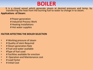


Boilers generate steam by transferring heat from burning fuel to water. There are two main types: fire-tube and water-tube. Factors that affect boiler selection include pressure, capacity, fuel type, and cost. Good boilers efficiently produce steam with minimal fuel and maintenance. Performance is evaluated through direct and indirect methods measuring efficiency, heat losses, and steam output. Regular testing helps identify issues and improve operation.


