2
Functions of D.C. Systems
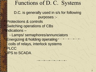
D.C. is generally used in s/s for following
purposes :-
• Protections & controls
• Switching operations of CBs
•Indications –
- Lamps/ semaphores/annunciators
• Energizing & holding operating
coils of relays, interlock systems
• PLCC
•UPS to SCADA
4
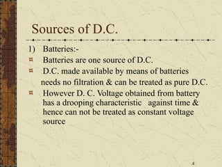
Sources of D.C.
1)Batteries:-
Batteries are one source of D.C.
D.C. made available by means of batteries
needs no filtration & can be treated as pure D.C.
However D. C. Voltage obtained from battery
has a drooping characteristic against time &
hence can not be treated as constant voltage
source
5.
5
Cont….
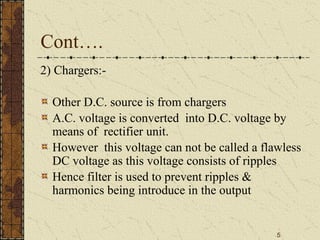
2) Chargers:-
Other D.C.source is from chargers
A.C. voltage is converted into D.C. voltage by
means of rectifier unit.
However this voltage can not be called a flawless
DC voltage as this voltage consists of ripples
Hence filter is used to prevent ripples &
harmonics being introduce in the output
6.
6
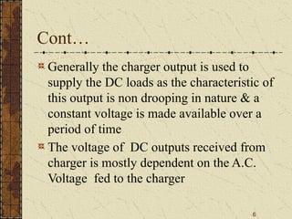
Cont…
Generally the chargeroutput is used to
supply the DC loads as the characteristic of
this output is non drooping in nature & a
constant voltage is made available over a
period of time
The voltage of DC outputs received from
charger is mostly dependent on the A.C.
Voltage fed to the charger
7.
7
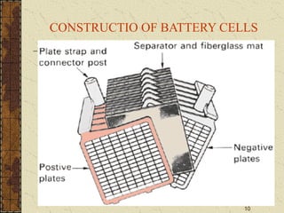
BATTERIES
The lead acidbattery is an electro chemical
device, invented in 1859 by GASTON PLANTE.
Lead acid battery stores electric energy in the
form of chemical energy & when called for,
reconverts the chemical energy back into electric
energy. This battery is also known as secondary
battery because this battery does not generate any
electrical energy, but only stores energy that is fed.
14
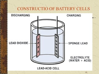
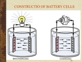
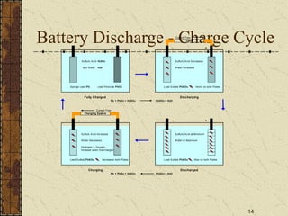
Battery Discharge -Charge Cycle
Current Flow
- + - +
Sulfuric Acid H2S04 Sulfuric Acid Decreases
and Water H20 Water Increases
Sponge Lead Pb Lead Peroxide PbO2 Lead Sulfate PbSO4 forms on both Plates
Pb + PbO2 + H2SO4 PbSO4 + H2O
Current Flow
- + - +
Sulfuric Acid Increases Sulfuric Acid at Minimum
Water Decreases Water at Maximum
Hydrogen & Oxygen
Increase when Overcharged
Lead Sulfate PbSO4 decreases both Plates Lead Sulfate PbSO4 Max on both Plates
Pb + PbO2 + H2SO4 PbSO4 + H2O
Load
Charging Discharged
Charging System
Fully Charged Discharging
15.
15
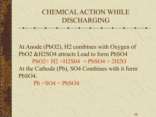
At Anode (PbO2),H2 combines with Oxygen of
PbO2 &H2SO4 attracts Lead to form PbSO4
PbO2+ H2 +H2S04 = PbSO4 + 2H2O
At the Cathode (Pb), SO4 Combines with it form
PbSO4.
Pb +SO4 = PbSO4
CHEMICAL ACTION WHILE
DISCHARGING
16.
16
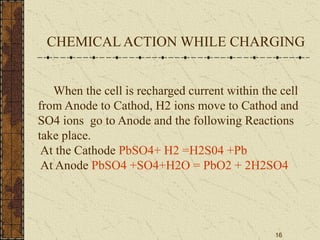
When the cellis recharged current within the cell
from Anode to Cathod, H2 ions move to Cathod and
SO4 ions go to Anode and the following Reactions
take place.
At the Cathode PbSO4+ H2 =H2S04 +Pb
At Anode PbSO4 +SO4+H2O = PbO2 + 2H2SO4
CHEMICAL ACTION WHILE CHARGING
17.
17
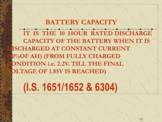
BATTERY CAPACITY
IT ISTHE 10 HOUR RATED DISCHARGE
CAPACITY OF THE BATTERY WHEN IT IS
DISCHARGED AT CONSTANT CURRENT
(10%OF AH) (FROM FULLY CHARGED
CONDITION i.e. 2.2V. TILL THE FINAL
VOLTAGE OF 1.85V IS REACHED)
(I.S. 1651/1652 & 6304)
18.
18
BATTERY CAPACITY
Eg. 200Ah: 10 Hrs @20 Amps till 1.85 VPC
1000 Ah :10 Hrs @100 Amps till 1.85vpc
CURRENT EQUIVALENT OF 10% OF AH
CAPACITY IS TERMED AS “C10” CURRENT
SIMILARLY,6% CURRENT AS “C6”
AND SO ON---
19.
19
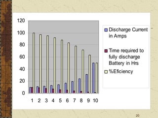
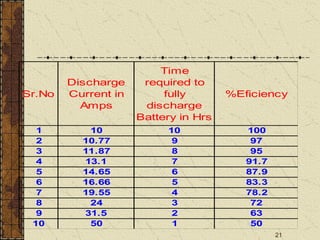
PERCENTAGE EFFICIENCY OFA
BATTERY
WHEN THE BATTRY IS ACTUALLY DISCHARGED
@ C10 CONSTANT CURRENT
THEN EFFICIENCY =
%=[CONSTANT CURRENT C10 X TIME REQD. TO REACH 1.85V] X100
{ACTUAL AH CAPACITY }
20.
20
0
20
40
60
80
100
120
1 2 34 5 6 7 8 9 10
Discharge Current
in Amps
Time required to
fully discharge
Battery in Hrs
%Eficiency
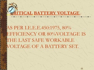
22
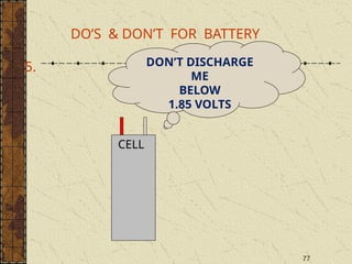
CRITICAL BATTERY VOLTAGE:
AS PER I.E.E.E.450:1975, 80%
EFFICIENCY OR 80%VOLTAGE IS
THE LAST SAFE WORKABLE
VOLTAGE OF A BATTERY SET.
23.
23
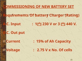
COMMISSIONING OF NEWBATTERY SET
Requirements Of battery Charger (Rating)
A.C. Input : 1 230 V or 3 440 V.
D.C. Out put
Current : 15% of Ah Capacity
Voltage : 2.75 V x No. Of cells
24.
24
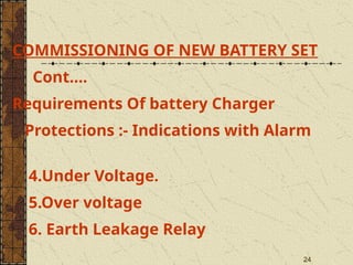
COMMISSIONING OF NEWBATTERY SET
Cont….
Requirements Of battery Charger
Protections :- Indications with Alarm
4.Under Voltage.
5.Over voltage
6. Earth Leakage Relay
25.
25
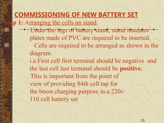
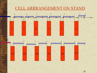
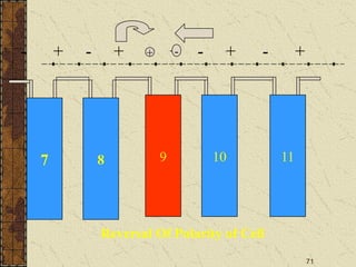
COMMISSIONING OF NEWBATTERY SET
Step 1: Arranging the cells on stand.
Under the legs of battery stand, stand insulator
plates made of PVC are required to be inserted.
Cells are required to be arranged as shown in the
diagram.
i.e.First cell first terminal should be negative and
the last cell last terminal should be positive.
This is important from the point of
view of providing 84th cell tap for
the boost charging purpose in a 220v
110 cell battery set
27
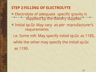
STEP 2:FILLING OFELECTROLYTE
Electrolyte of adequate specific gravity is
supplied by the battery supplier.
Initial sp.Gr. May vary as per manufacturer’s
requirements
i.e. Some mfr. May specify initial sp.Gr. as 1185,
while the other may specify the initial sp.Gr.
as 1190.
29
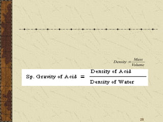
Correcting Sp. Gravityat 270
C
Sp Gravity should always be converted to
reference Temperature of 270
C
Sp. Gravity at Temp 270
C =
Sp.Gr. at Temp T0
C + 0.0007(T-27)
30.
30
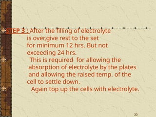
STEP 3 :After the filling of electrolyte
is over,give rest to the set
for minimum 12 hrs. But not
exceeding 24 hrs.
This is required for allowing the
absorption of electrolyte by the plates
and allowing the raised temp. of the
cell to settle down.
Again top up the cells with electrolyte.
31.
31
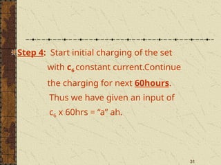
Step 4: Startinitial charging of the set
with c6 constant current.Continue
the charging for next 60hours.
Thus we have given an input of
c6 x 60hrs = “a” ah.
33
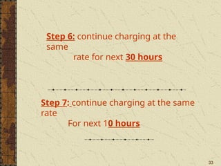
Step 6: continuecharging at the
same
rate for next 30 hours
Step 7: continue charging at the same
rate
For next 10 hours
34.
34
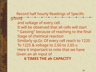
Record half hourlyReadings of Specific
gravity
and voltage of every cell.
It will be observed that all cells will start
“ Gassing” because of reaching to the final
Stage of chemical reaction
Similarly sp.Gr. Of every cell reach to 1220
To 1225 & voltage to 2.60 to 2.65 v.
Here it important to note that we have
Given an ah input of
6 TIMES THE ah CAPACITY
35.
35
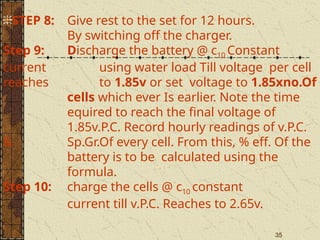
STEP 8: Giverest to the set for 12 hours.
By switching off the charger.
Step 9: Discharge the battery @ c10 Constant
current using water load Till voltage per cell
reaches to 1.85v or set voltage to 1.85xno.Of
cells which ever Is earlier. Note the time
equired to reach the final voltage of
1.85v.P.C. Record hourly readings of v.P.C.
& Sp.Gr.Of every cell. From this, % eff. Of the
battery is to be calculated using the
formula.
Step 10: charge the cells @ c10 constant
current till v.P.C. Reaches to 2.65v.
36.
36
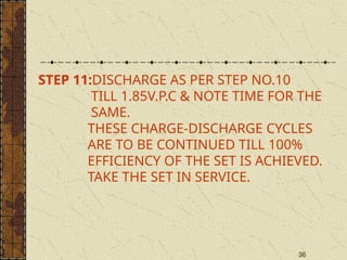
STEP 11:DISCHARGE ASPER STEP NO.10
TILL 1.85V.P.C & NOTE TIME FOR THE
SAME.
THESE CHARGE-DISCHARGE CYCLES
ARE TO BE CONTINUED TILL 100%
EFFICIENCY OF THE SET IS ACHIEVED.
TAKE THE SET IN SERVICE.
38
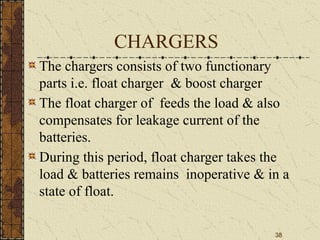
CHARGERS
The chargers consistsof two functionary
parts i.e. float charger & boost charger
The float charger of feeds the load & also
compensates for leakage current of the
batteries.
During this period, float charger takes the
load & batteries remains inoperative & in a
state of float.
40
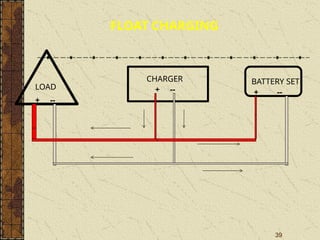
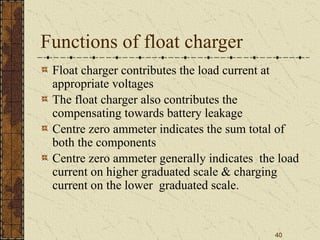
Functions of floatcharger
Float charger contributes the load current at
appropriate voltages
The float charger also contributes the
compensating towards battery leakage
Centre zero ammeter indicates the sum total of
both the components
Centre zero ammeter generally indicates the load
current on higher graduated scale & charging
current on the lower graduated scale.
41.
41
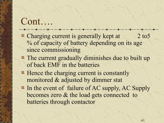
Cont….
Charging current isgenerally kept at 2 to5
% of capacity of battery depending on its age
since commissioning
The current gradually diminishes due to built up
of back EMF in the batteries
Hence the charging current is constantly
monitored & adjusted by dimmer stat
In the event of failure of AC supply, AC Supply
becomes zero & the load gets connected to
batteries through contactor
42.
42
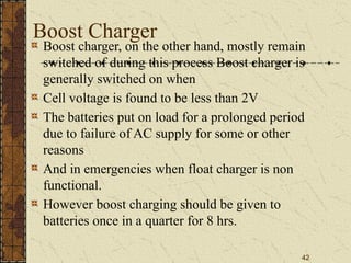
Boost Charger
Boost charger,on the other hand, mostly remain
switched of during this process Boost charger is
generally switched on when
Cell voltage is found to be less than 2V
The batteries put on load for a prolonged period
due to failure of AC supply for some or other
reasons
And in emergencies when float charger is non
functional.
However boost charging should be given to
batteries once in a quarter for 8 hrs.
43.
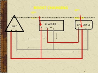
43
+ --
+ +--
LOAD
CHARGER BATTERY SET
+ --
BOOST CHARGING
42ND
CELL TAP
42ND
CELL TAP
44.
44
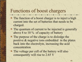
Functions of boostchargers
The function of a boost charger is to inject a high
current into the set of batteries that needs to be
charged.
The quantum of current to be injected is generally
above 8 to 10 % of capacity of battery
The purpose of the charge is to dislodge the
positive & negative ions embedded in the plates
back into the electrolyte, increasing the acid
concentration
The voltage per cell of the battery will also
consequently will rise to 2.65 V
45.
45
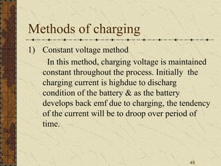
Methods of charging
1)Constant voltage method
In this method, charging voltage is maintained
constant throughout the process. Initially the
charging current is highdue to discharg
condition of the battery & as the battery
develops back emf due to charging, the tendency
of the current will be to droop over period of
time.
46.
46
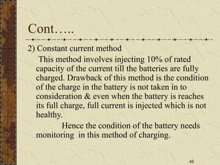
Cont…..
2) Constant currentmethod
This method involves injecting 10% of rated
capacity of the current till the batteries are fully
charged. Drawback of this method is the condition
of the charge in the battery is not taken in to
consideration & even when the battery is reaches
its full charge, full current is injected which is not
healthy.
Hence the condition of the battery needs
monitoring in this method of charging.
47.
47
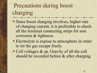
Precautions during boost
charging
Sinceboost charging involves, higher rate
of charging current, it is preferable to check
all the terminal connecting strips for non
corrosion & tightness.
Electrolyte is expose to atmosphere in order
to let the gas escape freely.
Cell voltages & sp. Gravity of all the cell
should be recorded before & after charging.
48.
48
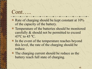
Cont…..
Rate of chargingshould be kept constant at 10%
of the capacity of the battery.
Temperature of the batteries should be monitored
carefully & should not be permitted to exceed
43ºC to 45 ºC.
In the event of the temperature reaches beyond
this level, the rate of the charging should be
reduce.
The charging current should be reduce as the
battery reach full state of charging.
49.
49
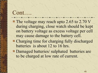
Cont….
The voltage mayreach upto 2.65 to 2.70 V
during charging, close watch should be kept
on battery voltage as excess voltage per cell
may cause damage to the battery cell.
Charging time for charging fully discharged
batteries is about 12 to 16 hrs.
Damaged batteries/ sulphated batteries are
to be charged at low rate of current.
50.
50
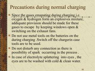
Precautions during normalcharging
Since the gases emanating during charging i.e.
oxygen & hydrogen form an explosives mixture,
addiquate provision should be made for these
gases to escape by keeping windows open &
switching on the exhaust fans.
Do not use metal tools on the batteries on the
during charging .Switch off the chargerin case
tools are to be used.
Do not disturb any connection as there is
possibility of spark occurring in the process .
In case of electrolyte splattering into eyes , the
eyes are to be washed with cold & clean water.
51.
51
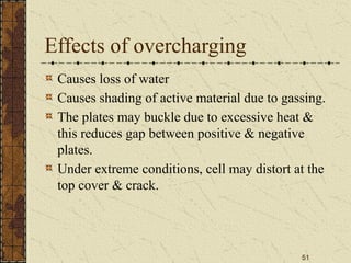
Effects of overcharging
Causesloss of water
Causes shading of active material due to gassing.
The plates may buckle due to excessive heat &
this reduces gap between positive & negative
plates.
Under extreme conditions, cell may distort at the
top cover & crack.
52.
52
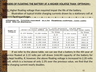
DANGERS OF FLOATINGTHE BATTERY AT A HIGHER VOLATGE THAN OPTIMUM:-
NOTE: Higher floating voltage than required impair the life of the battery.
Illustration of typical trickle charging currents drawn by a stationary cell at
different floating voltages.
(Ambient temperature - 270
C, Sp. Gr. - 1.210)
If we refer to the above table, we can see that a battery in the 4th year of
its service floated at 2.15 volts per cell draws 1mA/Ah capacity of the battery for
being kept healthy. If, however, the above floating voltage is increased to 2.20 volts
per cell, which is a increase of only 2.3% over the previous value, we find that the
trickle charging current nearly doubles.
53.
53
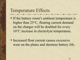
Temperature Effects
If thebattery room’s ambient temperature is
higher than 25°C, floating current demand
on the charger will be doubled for every
10°C increase in electrolyte temperature.
Increased float current causes excessive
wear on the plates and shortens battery life.
54.
54
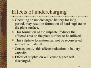
Effects of undercharging
Operatingan undercharged battery for long
period, may result in formation of hard suphate on
the plate surface.
This formation of the sulphate, reduces the
effected area on the plate surface to be utilized.
This sulphate formation can not be reconverted
into active material.
Consequently this affects reduction in battery
capacity.
Effect of sulphation will cause higher self
discharged.
55.
55
Importance of 84th
&55th
cell
84th
cell positive is generally connected to the
positive of load bus through a contactor
This arrangement is not fed to the load during
boost charging.
55th
cell negative is connected to earth through DC
ammeter in order to detect DC leakage current in
the system.
However it is to be ensured that the earth to which
55th
cell is connected is not linked to main earth
mat of the S/S in order to prevent fault potential
reaching the charger.
56.
56
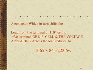
A contactor Whichin turn shifts the
Load from+ve terminal of 110th
cell to
+Ve terminal OF 84th
CELL & THE VOLTAGE
APPEARING Across the load reduces to
2.65 x 84 =222.6v.
58
MAINTENANCE OF ABATTERY SET
MAINTENANCE IS TO BE CARRIED OUT AS PER
M.S.S.XII & M.S.S.XII(a)
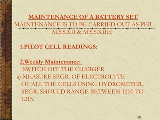
1.PILOT CELL READINGS:
2.Weekly Maintenance:
SWITCH OFF THE CHARGER
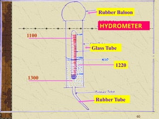
a) MEASURE SP.GR. OF ELECTROLYTE
OF ALL THE CELLS USING HYDROMETER.
SP.GR. SHOULD RANGE BETWEEN 1200 TO
1215.
59.
59
MAINTENANCE OF ABATTERY SET
MAINTENANCE IS TO BE CARRIED OUT AS
PER M.S.S.XII & M.S.S.XII(a)
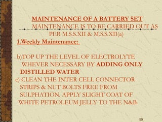
1.Weekly Maintenance:
b)TOP UP THE LEVEL OF ELECTROLYTE
WHEVER NECESSARY BY ADDING ONLY
DISTILLED WATER
c) CLEAN THE INTER CELL CONNECTOR
STRIPS & NUT BOLTS FREE FROM
SULPHATION. APPLY SLIGHT COAT OF
WHITE PETROLEUM JELLY TO THE N&B.
61
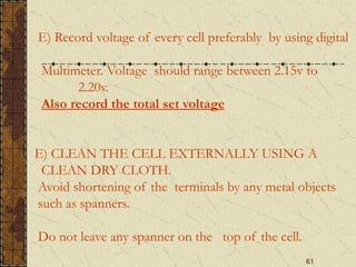
E) Record voltageof every cell preferably by using digital
Multimeter. Voltage should range between 2.15v to
2.20v.
Also record the total set voltage
E) CLEAN THE CELL EXTERNALLY USING A
CLEAN DRY CLOTH.
Avoid shortening of the terminals by any metal objects
such as spanners.
Do not leave any spanner on the top of the cell.
62.
62
F) Record temp.Of some of the cells randomly. Use only
alcohol type thermometer.
G) Clean the charger panel internally as well as externally.
Adjust the float voltage @2.15v.P.C.
63.
63
QUARTERLY MAINTENANCE
1.Carry outthe maintenance as per weekly maintenance.
2.Check & clean charger from inside.
3. Give boost charging treatment to the battery @ c10
constant current for 3-4 hours. During the boost
charging,
vent plugs of all the cell should be kept removed to
allow the gases to liberate freely in atmosphere.
4. Carry out maintenance of the exhaust fans
64.
64
ANNUAL MAINTENANCE
1.Carry outall the maintenance as per quarterly
maintenance procedure.
2.Give boost charge to battery @ C8 current.
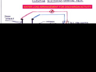
3Carry out curative discharge test /%efficiency test as
follows.
4 Switch “off” the charger
5 Connect water load to charger through a spare feeder
switch on D.C.D.B.
6.Check the total set voltage.
7.Through the water load start discharging the battery
@ c10 constant current
65.
65
ANNUAL MAINTENANCE
1.Carry outall the maintenance as per quarterly
maintenance procedure.
2.Give boost charge to battery @ C10 current.
3Carry out curative discharge test /%efficiency test as
follows.
4 Switch “off ” the charger
5 Connect water load to charger through a spare feeder
switch on D.C.D.B.
6.Check the total set voltage.
7.Through the water load start discharging the battery @
c10 constant current
66.
66
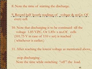
8. Note thetime of starting the discharge.
9. Record half hourly readings of voltage & sp.Gr. Of
every cell.
10. Note that discharging is to be continued till the
voltage 1.85 V.P.C. Or 1.85v x no.Of cells
(101.75 V in case of 110 v set) is reached
( whichever is earlier.)
11. After reaching the lowest voltage as mentioned above,
stop discharging .
Note the time while switching “off” the load.
67.
67
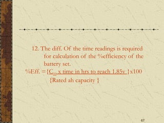
12. The diff.Of the time readings is required
for calculation of the %efficiency of the
battery set.
%Eff. ={C10 x time in hrs to reach 1.85v }x100
{Rated ah capacity }
68.
68
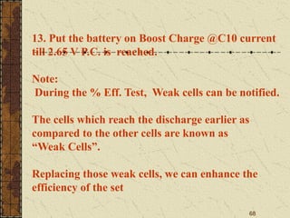
13. Put thebattery on Boost Charge @C10 current
till 2.65 V P.C. is reached.
Note:
During the % Eff. Test, Weak cells can be notified.
The cells which reach the discharge earlier as
compared to the other cells are known as
“Weak Cells”.
Replacing those weak cells, we can enhance the
efficiency of the set
69.
69
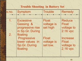
Trouble Shooting inBattery Set
s.no. Symptom Trouble Remedy
1.
2.
Excessive
Gassing &
progressive rise
in Sp.Gr. During
floating
Progressive
lower values in
Sp.Gr. During
floating
Float
voltage is
set high
Float
voltage is
set low.
Reduce
Float
voltage to
2.16 vpc
Increase
Float
voltage to
2.16 vpc
70.
70
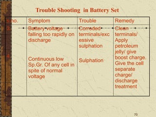
Trouble Shooting inBattery Set
s.no. Symptom Trouble Remedy
3.
4.
Battery voltage
falling too rapidly on
discharge
Continuous low
Sp.Gr. Of any cell in
spite of normal
voltage
Corroded
terminals/exc
essive
sulphation
Sulphation
Clean
terminals/
Apply
petroleum
jelly/ give
boost charge.
Give the cell
separate
charge/
discharge
treatment
72
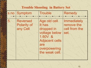
Trouble Shooting inBattery Set
s.no Symptom Trouble Remedy
5. Reversed
Polarity of
any Cell
Age old cell
It has
dropped in
voltage below
1.60V &
Adjacent cells
are
overpowering
the weak cell.
Immediately
remove the
cell from the
set.
73.
73
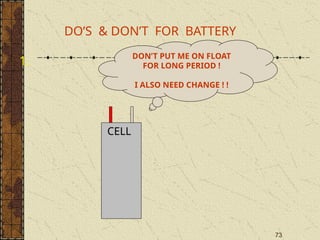
DO’S & DON’TFOR BATTERY
1.
CELL
DON’T PUT ME ON FLOAT
FOR LONG PERIOD !
I ALSO NEED CHANGE ! !
74.
74
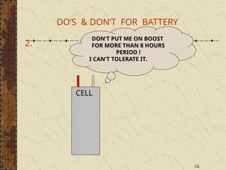
DO’S & DON’TFOR BATTERY
2.
CELL
DON’T PUT ME ON BOOST
FOR MORE THAN 8 HOURS
PERIOD !
I CAN’T TOLERATE IT.
75.
75
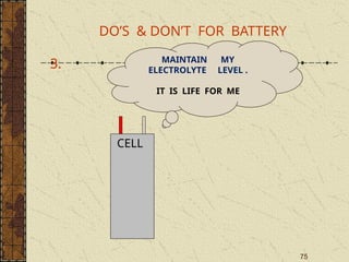
DO’S & DON’TFOR BATTERY
3.
CELL
MAINTAIN MY
ELECTROLYTE LEVEL .
IT IS LIFE FOR ME
76.
76
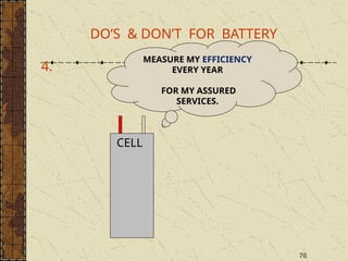
DO’S & DON’TFOR BATTERY
4.
CELL
MEASURE MY EFFICIENCY
EVERY YEAR
FOR MY ASSURED
SERVICES.
78
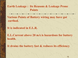
Earth Leakage :Its Reasons & Leakage Prone
Points
Various Points of Battery wiring may have got
earthed.
It is indicated in E.L.R.
E.L.Current above 20 mA is hazardous for battery
health.
It drains the battery fast & reduces its efficiency
79.
79
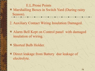
E.L.Prone Points
Marshalling Boxesin Switch Yard (During rainy
Season).
2. Auxiliary Contact Wiring Insulation Damaged.
Alarm Bell Kept on Control panel with damaged
insulation of wiring.
Shorted Bulb Holder.
Direct leakage from Battery due leakage of
electrolyte.


![19
PERCENTAGE EFFICIENCY OF A
BATTERY
WHEN THE BATTRY IS ACTUALLY DISCHARGED
@ C10 CONSTANT CURRENT
THEN EFFICIENCY =
%=[CONSTANT CURRENT C10 X TIME REQD. TO REACH 1.85V] X100
{ACTUAL AH CAPACITY }](https://image.slidesharecdn.com/battery11-1-250823034940-8956158b/85/Battery-Maintenance-maintenanmaintenance-19-320.jpg)