The document summarizes testing done to measure the electromagnetic interference (EMI) shielding effectiveness of a metallic mesh coating applied to a sapphire window. Metallic mesh coatings can provide both high optical transmittance and EMI shielding. Testing was conducted from 10 kHz to 18 GHz on a test assembly consisting of the coated window mounted in a conductive frame. Measured shielding effectiveness agreed with predictive models from 1-18 GHz but was lower below 300 MHz likely due to low signal levels. The metallic mesh coating performed as predicted and provides viable broadband EMI shielding.
Wireless electronic devices nowadays always operate in high frequency while having small and compact form factor which led to electromagnetic interference among traces and components. PCB shielding is the common solution applied in electronic industry to mitigate electromagnetic interference. In this paper, PCB shielding characteristics such as shield’s thickness, height, and ground via spacing in PCB boards were evaluated in near field. Test boards with various grounds via spacing were fabricated and evaluated by using 3D Electromagnetic scanner. On the other hand, shields with various thickness and height were modeled and evaluated through simulation. Results suggested that shielding effectiveness could be improved by having greater shield’s height with smaller ground via spacing in shielding ground tracks. Shielding effectiveness can be improved by 1 dB with every step of 0.5 mm increase in shield’s height. Besides that, approximately 0.5 dB improvement in shielding effectiveness with every step of 1 mm decrease in ground via spacing. Furthermore, greater shield’s thickness can contribute better shielding effectiveness for operating frequency below 300 MHz.
IJERA (International journal of Engineering Research and Applications) is International online, ... peer reviewed journal. For more detail or submit your article, please visit www.ijera.com
Electromagnetic Bandgap Structure for Antenna Design iosrjce
A dual band electromagnetic band gap structure is designed, simulated and measured. This is
carried out using CST microwave studio software, the design is carried out on FR-4 substrate by Method of
Suspended Transmission Line. The structure posses a dual band gap that effectively suppress surface wave at
the dual frequencies. The result from the simulation gives dual band gaps that resonate at 1.8GHz and 4.0GHz
and the measured result resonate at 1.8GHz and 4.3GHz, this show there is a good agreement between the two
results. The structure is simple and easily incorporated with microwave and wireless devices
Effect of EBG Structures on the Field Pattern of Patch Antennas ijmnct
The incorporation of number of unit cells in EBG arrangement produces two major side effects on the performance of patch antenna. First one is parasitic loading, this causes multi resonance in antenna hence obtains some enhancement in antenna band width. Second one is cavity effect, this reflects some of energy from EBG toward antenna which results in reducing bandwidth. Present paper, rectangular microstrip patch
antenna is surrounded by number of EBG rows is designed; and the results of proposed antenna with a conventional patch antenna is presented comparatively.
Effect of EBG Structures on the Field Pattern of Patch Antennas ijeljournal
The incorporation of number of unit cells in EBG arrangement produces two major side effects on the
performance of patch antenna. First one is parasitic loading, this causes multi resonance in antenna hence
obtains some enhancement in antenna band width. Second one is cavity effect, this reflects some of energy
from EBG toward antenna which results in reducing bandwidth. Present paper, rectangular microstrip patch
antenna is surrounded by number of EBG rows is designed; and the results of proposed antenna with a
conventional patch antenna is presented comparatively.
Effect of EBG Structures on the Field Pattern of Patch Antennas ijeljournal
The incorporation of number of unit cells in EBG arrangement produces two major side effects on the performance of patch antenna. First one is parasitic loading, this causes multi resonance in antenna hence obtains some enhancement in antenna band width. Second one is cavity effect, this reflects some of energy from EBG toward antenna which results in reducing bandwidth. Present paper, rectangular microstrip patch
antenna is surrounded by number of EBG rows is designed; and the results of proposed antenna with a conventional patch antenna is presented comparatively.
Effect of EBG Structures on the Field Pattern of Patch Antennas ijeljournal
The incorporation of number of unit cells in EBG arrangement produces two major side effects on the performance of patch antenna. First one is parasitic loading, this causes multi resonance in antenna hence obtains some enhancement in antenna band width. Second one is cavity effect, this reflects some of energy from EBG toward antenna which results in reducing bandwidth. Present paper, rectangular microstrip patch antenna is surrounded by number of EBG rows is designed; and the results of proposed antenna with a conventional patch antenna is presented comparatively.
Effect of EBG Structures on the Field Pattern of Patch Antennasijeljournal
The incorporation of number of unit cells in EBG arrangement produces two major side effects on the
performance of patch antenna. First one is parasitic loading, this causes multi resonance in antenna hence
obtains some enhancement in antenna band width. Second one is cavity effect, this reflects some of energy
from EBG toward antenna which results in reducing bandwidth. Present paper, rectangular microstrip patch
antenna is surrounded by number of EBG rows is designed; and the results of proposed antenna with a
conventional patch antenna is presented comparatively.
Effect of EBG Structures on the Field Pattern of Patch Antennas ijeljournal
The incorporation of number of unit cells in EBG arrangement produces two major side effects on the performance of patch antenna. First one is parasitic loading, this causes multi resonance in antenna hence obtains some enhancement in antenna band width. Second one is cavity effect, this reflects some of energy from EBG toward antenna which results in reducing bandwidth. Present paper, rectangular microstrip patch antenna is surrounded by number of EBG rows is designed; and the results of proposed antenna with a conventional patch antenna is presented comparatively.
Performance Improvement of Microstrip antenna using Fractal EBG structure and...iosrjce
IOSR Journal of Electrical and Electronics Engineering(IOSR-JEEE) is a double blind peer reviewed International Journal that provides rapid publication (within a month) of articles in all areas of electrical and electronics engineering and its applications. The journal welcomes publications of high quality papers on theoretical developments and practical applications in electrical and electronics engineering. Original research papers, state-of-the-art reviews, and high quality technical notes are invited for publications.
PERFORMANCE ANALYSIS OF 2D-EBG UNDER MONOPOLE ANTENNAjantjournal
The artificial properties in two dimensional electromagnetic structures (2D-EBGs), such as PMC and Band Reject Region are investigated for a proposed structure of square shaped mushroom. The radiation characteristics of monopole antenna over this 2D-EBG is tested by considering two cases. During first case monopole antenna is made to operate within band rejection region. Second case monopole antenna made operate outside the band rejection range. The obtained results during first case is showing enhancement in operating band width and smoother radiation pattern. In second case the effect is null and
2D-EBG resembles like conventional plane reflector. The simulated results are presented.
Reduction of Mutual Coupling between Closely Spaced Microstrip Antennas Array...TELKOMNIKA JOURNAL
Reducing mutual coupling is a key research area in design of compact microstrip antennas
arrays. To minimize the overall size of the antennas arrays, the distance between them must be very
small, as a result a strong mutual coupling is appears. Periodic structures can help to design a low profile
of antennas arrays and enable to improve their performances by the suppression of surface waves
propagation in a given frequency range. This paper proposes a novel configuration of mushroom-like
electromagnetic band-gap (2D-EBG) structure created by microstrip technology placed between two
antennas arrays to reduce the mutual coupling more than -33.24dB. When 13×2 EBG structures are used,
the mutual coupling reduces to -59.36dB at the operation frequency 5.8GHz of the antennas arrays. A
26.12dB mutual coupling reduction is achieved, which proves that the surface wave is suppressed. The
proposed configuration is designed, optimized, and miniaturized by using electromagnetic software CST
Microwave Studio. The measured results show that there is a good agreement with the computed results.
INSPECTION OF GFRP COMPOSITES BY MICROWAVE NDEjmicro
Fiber reinforced polymer (FRP) composites form a major structural part ofaerospace and defence
applications. Non-destructive evaluation (NDE) plays an important role in assessing the quality and
health monitoring of FRP composite structures.Defect detection of FRPcomposite structures are by
different NDE techniques, such as ultrasonics, thermography, X-ray radiography. Depending on the type
of material, their characteristic features and accessibility of the test object etc. suitable techniquesare
employed. Microwave non-destructive evaluation (MWNDE) is an emerging NDE technique for
characterizing and inspecting dielectric structures. Microwave NDE finds application in the areas of
dielectric material characterization, determining thickness variation, defect detection and bond quality
inspection.Inspection of glass fiber reinforced polymer (GFRP) composites by near-field reflection
microwave NDE technique is presented in this paper. GFRP composite with known inserted defects such
as inclusion and flat bottom holes are inspected to understand and establish Microwave NDE. Results of
inspected structures by swept frequency reflection microwave NDE technique in the frequency range 8.2-
12.4GHz (X-band) and 12.4-18GHz (Ku-band) respectively are presented. The position of the reflection
characteristic curve indicates the depth of the defect in the inspected structure.
Effect of EBG Structures on the Field Pattern of Patch Antennas ijeljournal
The incorporation of number of unit cells in EBG arrangement produces two major side effects on the performance of patch antenna. First one is parasitic loading, this causes multi resonance in antenna hence obtains some enhancement in antenna band width. Second one is cavity effect, this reflects some of energy from EBG toward antenna which results in reducing bandwidth. Present paper, rectangular microstrip patch antenna is surrounded by number of EBG rows is designed; and the results of proposed antenna with a conventional patch antenna is presented comparatively.
Effect of EBG Structures on the Field Pattern of Patch Antennasijeljournal
The incorporation of number of unit cells in EBG arrangement produces two major side effects on the
performance of patch antenna. First one is parasitic loading, this causes multi resonance in antenna hence
obtains some enhancement in antenna band width. Second one is cavity effect, this reflects some of energy
from EBG toward antenna which results in reducing bandwidth. Present paper, rectangular microstrip patch
antenna is surrounded by number of EBG rows is designed; and the results of proposed antenna with a
conventional patch antenna is presented comparatively.
Effect of EBG Structures on the Field Pattern of Patch Antennas ijeljournal
The incorporation of number of unit cells in EBG arrangement produces two major side effects on the performance of patch antenna. First one is parasitic loading, this causes multi resonance in antenna hence obtains some enhancement in antenna band width. Second one is cavity effect, this reflects some of energy from EBG toward antenna which results in reducing bandwidth. Present paper, rectangular microstrip patch antenna is surrounded by number of EBG rows is designed; and the results of proposed antenna with a conventional patch antenna is presented comparatively.
Performance Improvement of Microstrip antenna using Fractal EBG structure and...iosrjce
IOSR Journal of Electrical and Electronics Engineering(IOSR-JEEE) is a double blind peer reviewed International Journal that provides rapid publication (within a month) of articles in all areas of electrical and electronics engineering and its applications. The journal welcomes publications of high quality papers on theoretical developments and practical applications in electrical and electronics engineering. Original research papers, state-of-the-art reviews, and high quality technical notes are invited for publications.
PERFORMANCE ANALYSIS OF 2D-EBG UNDER MONOPOLE ANTENNAjantjournal
The artificial properties in two dimensional electromagnetic structures (2D-EBGs), such as PMC and Band Reject Region are investigated for a proposed structure of square shaped mushroom. The radiation characteristics of monopole antenna over this 2D-EBG is tested by considering two cases. During first case monopole antenna is made to operate within band rejection region. Second case monopole antenna made operate outside the band rejection range. The obtained results during first case is showing enhancement in operating band width and smoother radiation pattern. In second case the effect is null and
2D-EBG resembles like conventional plane reflector. The simulated results are presented.
Reduction of Mutual Coupling between Closely Spaced Microstrip Antennas Array...TELKOMNIKA JOURNAL
Reducing mutual coupling is a key research area in design of compact microstrip antennas
arrays. To minimize the overall size of the antennas arrays, the distance between them must be very
small, as a result a strong mutual coupling is appears. Periodic structures can help to design a low profile
of antennas arrays and enable to improve their performances by the suppression of surface waves
propagation in a given frequency range. This paper proposes a novel configuration of mushroom-like
electromagnetic band-gap (2D-EBG) structure created by microstrip technology placed between two
antennas arrays to reduce the mutual coupling more than -33.24dB. When 13×2 EBG structures are used,
the mutual coupling reduces to -59.36dB at the operation frequency 5.8GHz of the antennas arrays. A
26.12dB mutual coupling reduction is achieved, which proves that the surface wave is suppressed. The
proposed configuration is designed, optimized, and miniaturized by using electromagnetic software CST
Microwave Studio. The measured results show that there is a good agreement with the computed results.
INSPECTION OF GFRP COMPOSITES BY MICROWAVE NDEjmicro
Fiber reinforced polymer (FRP) composites form a major structural part ofaerospace and defence
applications. Non-destructive evaluation (NDE) plays an important role in assessing the quality and
health monitoring of FRP composite structures.Defect detection of FRPcomposite structures are by
different NDE techniques, such as ultrasonics, thermography, X-ray radiography. Depending on the type
of material, their characteristic features and accessibility of the test object etc. suitable techniquesare
employed. Microwave non-destructive evaluation (MWNDE) is an emerging NDE technique for
characterizing and inspecting dielectric structures. Microwave NDE finds application in the areas of
dielectric material characterization, determining thickness variation, defect detection and bond quality
inspection.Inspection of glass fiber reinforced polymer (GFRP) composites by near-field reflection
microwave NDE technique is presented in this paper. GFRP composite with known inserted defects such
as inclusion and flat bottom holes are inspected to understand and establish Microwave NDE. Results of
inspected structures by swept frequency reflection microwave NDE technique in the frequency range 8.2-
12.4GHz (X-band) and 12.4-18GHz (Ku-band) respectively are presented. The position of the reflection
characteristic curve indicates the depth of the defect in the inspected structure.
Integrante do Grupo Natural Line a MOVE vem de 30 anos fabricando para empresas dentro e fora do Pais.
Move! é a evolução do MMN de produtos, a melhor e mais completa empresa da atualidade.
Vem ser Pioneiro
MOVE!
A LITERATURE SURVEY ON ELECTROMAGNETIC SHIELDINGIJEEE
EMI (electromagnetic interference) is the disruption of operation of an electronic device when it is in the vicinity of an electromagnetic field (EM field) in the radio frequency (RF) spectrum that is caused by another electronic device. It is a disturbance that affects an electrical circuit due to either electromagnetic induction or electromagnetic radiation emitted from an external source. The disturbance may interrupt, obstruct, or otherwise degrade or limit the effective performance of the circuit. Here we study about the shielding theory so as to reduce the effects of EMI.
Analysis of Circular Patch Antenna Embeded on Silicon Substrateijceronline
International Journal of Computational Engineering Research (IJCER) is dedicated to protecting personal information and will make every reasonable effort to handle collected information appropriately. All information collected, as well as related requests, will be handled as carefully and efficiently as possible in accordance with IJCER standards for integrity and objectivity.
Frequency Dependent Characteristics of OGMOSFETidescitation
Miniaturization in length, lowering of power,
increase in package density and sensitivity to light of
MOSFET leads it as the potential candidate for RF application.
As device is expected to operate at RF, it is essential to observe
its frequency dependent characteristics at RF. In this paper
frequency dependent electro optical characteristics of
Optically Gated Metal Oxide Semiconductor Field Effect
Transistor (OGMOSFET) are investigated numerically.
Variation of drain current-voltage characteristics, gate
capacitance and transconductance of OGMOSFET, with
varying frequency, is reported. MOSFET having length of
0.35μm is selected for investigation, which is optically gated
with incident radiations of optical power of 0.25mW and
wavelength of 800nm. MATLAB is used as computational
platform to test and tune the results. Results show that
increase in modulating frequency of OGMOSFET decreases
drain current, gate capacitance, transconductance and output
conductance. This is due to decrease in life time of inversion
charges at very high frequencies. Operating bandwidth of the
device is up to 4GHz.
Shielding Effect Analysis of Em Waves for Oblique Incidence in Double Shieldsiosrjce
Shielding effectiveness analysis of double shields with conductors using plane-wave theory are
carried out as a function of angle of incidence. The plane wave shielding effectiveness of new combination of
these materials is evaluated for the double shields. Stable highly conductive materials , with characteristics of
light-weight, mechanically strong materials are considered for shielding the EMI. The analysis is done at a
particular frequency for double shields of aluminum and copper polymers.
Shielding Effect Analysis of Em Waves for Oblique Incidence in Double Shields
battelle_predicted_emi_paper
1. Predicted and measured EMI shielding effectiveness of a metallic mesh
coating on a sapphire window over a broad frequency range
Keith T. Jacoby*a
, Matthew W. Pieratta
, Jennifer I. Halmanb
, Keith A. Ramseyb
a
Exotic Electro-Optics (EEO), 36570 Briggs Rd Murrieta, CA 92563;
b
Battelle Memorial Institute (BMI), 505 King Avenue Columbus, OH 43201
ABSTRACT
Metallic mesh thin film coatings have been used for many years to provide electromagnetic interference (EMI) shielding
on infrared windows and domes. The level of EMI shielding effectiveness (SE) of metallic mesh coatings when used in a
high frequency application is understood and characterized. Conversely, the level of SE of these metallic mesh coatings
when used in a low frequency application has been called into question. In a recent study, we applied an appropriately
designed metallic mesh coating to a sapphire window, mounted that window in a fixture, and tested the SE of the
window assembly over a frequency range that envelopes the various military platforms covered in MIL-STD-461 (10
kHz to 18 GHz) for a radiated emissions test. The test plan was devised in such a way as to independently assess the
individual contributions of the aperture, the mounting, and the metallic mesh coating to the total shielding. The results of
our testing will be described in this paper. Additionally, the test results will be compared to the predicted SE for both the
aperture and the metallic mesh coated window in order to validate the predictive model. Finally, an assessment of the
appropriateness of the use of metallic mesh coatings for EMI shielding in a low and / or broad range frequency
application will be made.
Keywords: EMI, shielding effectiveness, metallic mesh coatings, grids, sapphire
1. INTRODUCTION
Proper electromagnetic shielding is an important factor in providing protection for sensitive equipment in both military
and civilian applications, such as sensors. Undesirable radiation can cause electromagnetic interference (EMI), which
can take the form of damage or other unacceptable responses in operation. Often, testing for various military
applications conforms to MIL-STD-461, which specifies electromagnetic compliance (EMC) for conducted emissions,
conducted susceptibility, radiated emissions and radiated susceptibility. Susceptible components to EMI are often
located behind optics. System designers establish functional exposure levels for internal circuitry to outside or
controlled radiation, resulting in the flowing down of the proper requirements to the manufacturer of the optic or optical
assembly. Thus, shielding against EMI is used to reduce radiated emissions from a system or reduce radiated
susceptibility of a system and the term often used for such a specification is shielding effectiveness (SE).
Fundamentally, SE is the ratio of the incident wave to the transmission wave for either the electric field (most common)
or magnetic field, whether in the near-field or far-field.
This effort attempts to move closer to a definitive answer to the following questions:
1. Are the appropriately designed metallic mesh coatings a viable solution to a broadband EMI shielding problem?
2. Can metallic mesh coatings provide shielding at the lower frequencies range?
3. Can a test method be developed that quantifies the contribution of the metallic mesh coating and substrate to the
overall shielding effectiveness of a test assembly?
4. Does the existing model accurately predict the SE of a metallic mesh coated window from 10 KHz to 18GHz?
This paper describes the results of modeling and experimentation specifically designed to address those questions for a
metallic mesh coating on a sapphire window. Battelle Memorial Institute deposited the metallic mesh coating and
provided the theoretical model. Exotic Electro-Optics provided the fabricated sapphire window and conducted the
testing and analysis.
*kjacoby@exotic-eo.com; phone 1 951 926-7663; fax 1 951 926-1984; www.exotic-eo.com
2. t
i
E
E
SE 10log20
2. GRID COATING DESIGN AND MODEL PREDICTION
Metallic mesh coatings are routinely deposited on infrared windows to provide electromagnetic shielding to the
electronics and sensors operating behind the windows. An example of a metallic mesh coating using a square mesh
pattern is shown in Figure 1.
Figure 1: Typical Square Mesh Coating, 5 µm wide lines, 50 µm center-to-center line spacing.
The advantage of a mesh coating over a continuous conductive coating is that the mesh will provide high visible and
infrared transmittance while also providing high microwave and RF shielding. Continuous conductive coatings such as
indium tin oxide, In2-xSnxO3, or ITO, can be used to provide shielding for visible window applications, but for many
applications mesh coatings can provide higher optical/IR transmittance, lower effective sheet resistance, and higher
shielding. ITO and most continuous conductive coatings do not transmit well in the infrared.
The visible and infrared transmittance of a mesh coating is a function of the geometry of the mesh. The total visible or
infrared transmittance of the mesh is equal to the percent open area of the mesh. Due to diffraction by the grid at visible
and infrared wavelengths, the transmittance of the mesh through the zero-order or main diffraction lobe is approximately
equal to the square of the percent open area.
Several factors control the SE of a metallic mesh coating. Thicker metal will decrease the effective sheet resistance of
the mesh, increasing the shielding, especially at the lower frequencies. Increasing the line widths of a mesh and reducing
the spacing between the lines will also increase the shielding, but these changes will also reduce the visible and infrared
transmittance.
Metallic mesh coatings do have the disadvantage of diffraction versus continuous coatings. Although diffraction cannot
be eliminated when using a mesh, the effects can be reduced by randomizing the pattern and/or selecting a non-uniform
pattern.
Shielding Effectiveness Predictions
SE is the attenuation of an incident electromagnetic plane wave field as it is transmitted through the mesh-coated
window,
(1)
where Ei and Et are the incident and transmitted electric fields, respectively. As long as the thickness of the mesh coating
is much less than a skin depth, δ, where the skin depth is defined as follows:
3. frequency,
andty,conductivi
ty,permeabili
,2
,
2
f
f
t
Rc
1
0
0
0
0
10
2
1
1
log20
where
R
SE
c
,ceff R
l
g
R
(2)
the SE is almost entirely due to reflection of the incident plane wave at the air to mesh interface. Mesh coatings are
usually less than 1 or 2 µm thick and the skin depth of gold at 18 GHz is 0.56 µm, so the mesh coatings are generally
much less than a skin depth for microwave and lower frequencies.
The transmission coefficient of an infinite metallic sheet of thickness t due to a normally incident plane electromagnetic
wave is given by transmission line theory.1
For thin continuous conductive films the transmission coefficient and the SE
is independent of frequency and can be characterized by the sheet resistance of the coating, Rc,
(3)
As long as the thickness t is less than the skin depth and the conductive coating has low intrinsic impedance compared to
free space, ignoring the effects of the substrate, the SE is2
(4)
The SE of a metallic mesh coating depends on frequency as well as the sheet resistance of the metal comprising the
mesh, the mesh geometry, the permittivity of the window material, and the thickness of the window.
At low frequencies, as long as the incident fields are plane waves, a metallic mesh coating performs as a continuous
conductive coating. The SE is given by equation 4, using an effective sheet resistance, Reff, in place of Rc. The effective
sheet resistance of a square mesh coating is
(5)
where g is the line spacing and l is the line width. As the frequency increases, the frequency dependence of the mesh
must be taken into account. Battelle has modeled the plane wave transmittance of a mesh coated window as a function
of frequency. The model is based on the transmission coefficient analysis for arbitrary layered media by Ruck3
and an
empirically developed frequency-dependent model for the impedance of the finitely conductive metallic mesh coating.
Based on a Battelle’s model of the plane wave transmittance of multilayer structures, the SE of a metallic mesh coating
with 5 micron-wide lines and 50 micron line spacing as a function of frequency is shown in Figure 2. Taking into
consideration the continuous metal sheet resistance, the effective sheet resistance of this mesh coating is 0.2 ohms/sq.
4. Figure 2: Predicted shielding effectiveness of a 5x50 square mesh coating on 0.25-inch thick sapphire
The SE of a continuous coating with a sheet resistance of 0.2 ohms/sq is approximately 60 dB at DC. At low
frequencies, where the apertures in the mesh are much smaller than a wavelength, the mesh will perform exactly like a
thin continuous conductive film of the same sheet resistance.
At higher frequencies, where the wavelengths are nearer to the dimensions of the apertures in the mesh, the mesh begins
to leak and the SE is reduced as frequency increases.
3. PANEL AND TEST FIXTURING CONFIGURATION
A patterned conductive mesh coating and buss bars were applied by Battelle to one side of a 10 ½ x 8 ½ x ¼ inch thick
polished sapphire window fabricated by Exotic Electro-Optics. The mesh coating was patterned in the central 9 ¾ x 7 ¾
inch area and terminated with a solid buss bus bar applied around the entire perimeter of the coated side of the panel. The
mesh coating and the buss bar have the same metal stack composition. The test frame and retainer are made out of 6061-
T6 aluminum. The retainer is held to the back of the frame by 16x 8-32 stainless steel socket head cap screws. The recess
in the frame was sized to hold a 0.125 inch thick conductive silicone gasket (MIL-G-E352E), the mesh coated sapphire
window, and a 0.125 inch thick silicone gasket. The compression in the conductive gasket developed when the retainer
was torqued down 15-25%. The frame is mounted to the test chamber wall using 12x ¼-20 steel socket head cap screws.
The assembly is built up in the following sequence: frame – conductive gasket – conductive side of window – silicone
gasket – retainer. Figures 3 and 4 shows the test assembly.
5. Figure 3: Window and Test Fixture Configuration
Figure 4: The window is put in place with the conductive gasket making contact with the buss bar and the fixture.
A non-conducting gasket and retainer are placed on the opposite side to sandwich the window in place.
6. 4. TEST PROCEDURE
Approach
The goal of the testing is to determine the contribution of the window to the assembly’s total SE. A series of test runs
were performed that would allow for the extraction of the window’s SE. The following is a list of the measurements
performed for each of the four antenna set-ups:
a) Open aperture (nothing in pass through): Establishes baseline for comparison to all measurements.
b) Solid Aluminum Plate: Measures leakage around frame mounting and permeability of aluminum.
c) Frame: Establishes baseline for window SE contribution.
d) Frame + Solid Al Plate: Measures leakage around conductive gasket.
e) Frame + Window: Measure of the total SE of the test assembly.
Experimental setup
Testing was performed at Stork-Garwood Laboratories (Pico Rivera, California). The setup at Garwood consists of two
chambers lined with 1mm thick galvanized steel on both sides of 18mm thick particle board, and an opening between the
two rooms for a unit under test (UUT). The source antenna was placed in the larger room with dimensions of 3.65m x
5.5 m x 3.65 m and the receiving antenna was placed in the smaller room with dimensions of 3.05 m x 3.65 m x 3.65 m
(see Figure 5). The open aperture is 0.5 m wide and 0.35 m high (20 inches x 14 inches), and located 1.5m up from the
conductive floor. The test fixture’s aperture is about 0.25 m wide and 0.20 m high (10 inches x 8 inches).
Figure 5: Experimental setup: includes dimensions of the chamber, antenna spacing, and material composition of
chamber.
Different antennas were used for specific frequency ranges and are listed in Table 1. The biconical antenna was tested at
3 m separation and, though not listed in the table, tested again at 6 m in an attempt to create a ―more plane-wave‖ EM
field.
Table 1: Frequency range for each antenna configuration. The wavelength range is also listed for reference.
Frequency Range Antenna type Total separation Wavelength
10kHz to 30MHz 12 inch loop 1 m 30km to 10m
30MHz to 200MHz Biconical 3 m 10m to 1.5m
200MHz to 1GHz Log periodic 3 m 1.5m to 0.3m
1GHz to 18GHz Horn (double ridge
guide)
1 m 0.3m to 1.7cm
7. Different setups were used in hopes of achieving a more accurate SE result. The following pictures show the various
setups and antennas being used. The terms chosen and pictures should aid in understanding the results following.
Figure 6: Loop antenna setup with the receive antenna Figure 7: Biconical antenna tested at both 3m and 6m
shown. separation. The one shown above is the latter, 4m from
the wall on the transmitting side. Note the sparse cones
in the figure.
Figure 8: Log antenna on receiving side. Figure 9: Horn antenna on receiving side.
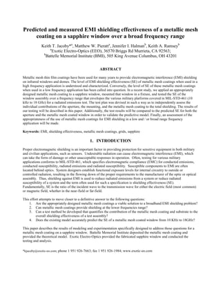
8. 5. COMPARISION OF MODEL PREDICTED PERFORMANCE AND TEST RESULTS
The results of the SE measurements compared to the model predictions are shown in Figure 10 and Figure 11. The trend
of the measured data agrees with the model from about 1 to 18 GHz, although the measured SE is higher than expected.
The measured SE continues to increase as the frequency decreases as expected until the frequency reaches about 300
MHz. The measured SE drops below the expected value below about 300 MHz. This may be due to low signal-to-noise
ratios at low frequency or because at low frequencies the measurements are in the near field and the incident radiation is
not in the form of plane waves. At 1 GHz, the wavelength is 0.3 meters. At 10 MHz, the wavelength is 30 meters. The
size of the aperture is 0.267 m by 0.216 m. The energy that gets through the small aperture at low frequencies is low
even when there is no window present. Most of the energy is blocked by the small aperture.
Figure 10: Predicted and measured shielding effectiveness of a 5x50 square mesh coating on 0.25-inch thick
sapphire, 1 to 18 GHz
9. ,
5.0
log20
d
SEaperture
Figure 11: Predicted and measured shielding effectiveness of a 5x50 square mesh coating on 0.25-inch thick
sapphire, 0 to 1 GHz
6. OTHER CONSIDERATIONS
The SE for the window was attained by exposing the aperture of the fixture, also known as the ―small opening‖, which
included the retainer and gasket, and then exposing the same configuration with the window in place. For the lowest
frequency band, 10 kHz to 30 MHz, a loop antenna was used, which has a large magnetic-field component. Aluminum
is a poor magnetic shield for the lower frequencies. This became evident from 10 kHz to 100 kHz, where there was
almost zero dB shielding, for both the window and the aluminum plate measurements. With limitations in shielding
against magnetic near-field, the data for the loop antenna is suspect.
For the next frequency range, 30 MHz to 200 MHz, a biconical antenna was used. Again, the measured SE decreased as
the frequency decreased. To make the measurements more ―plane-wave‖ in this region the antenna separation was
increased from 3 m to 6 m, but no clear difference was detected.
The log periodic antenna was used in the frequency range from 200 MHz to 1 GHz. This data does follow the trend of
the biconical data and is much closer to the predicted SE, though the periodic nature is not fully understood. The double
ridged horn antenna was used for frequencies greater than 1 GHz. The dips in the data are a function of the thickness of
the material, the frequency and the dielectric constant. The horn antenna was oriented in the vertical direction, as were
the other antennas (excluding the loop antenna), which passes through the c-axis of the sapphire window. The dielectric
constant for this orientation is about 11.4.
A concern arises that the size of the aperture is reducing the incident energy—acting as a shield itself. As a rule of
thumb, the SE due to the size of a rectangular aperture is approximately4
(6)
10. where λ is the wavelength and d is the largest dimension, and d is less than or equal to half of λ. However, this is the
worst case scenario for aperture leakage, whereas our concern is with too much shielding of the aperture and our aperture
orientation is with respect to the smaller dimension, 0.2 meters. As such, the aperture shielding begins to play a small
effect when the frequency is just below about 750 MHz and plays an even greater effect as the frequency decreases.
Figure 12 compares the aperture shielding to the window shielding and the shielding of a small aluminum plate. When
the aluminum plate is substituted for the window, the results are nearly the same below 1 GHz. The shielding of
aluminum at these frequencies is expected to be high, above 100 dB, so the aperture appears to have an effect on the
results. When a comparison is made of the SE of the window with respect to the small aperture and the window with
respect to the large aperture, an additional 5 to 20 dB of shielding was observed from about 30 MHz to 500 MHz, due to
the larger aperture. A comparison was made between the large metal plate’s shielding and the shielding of the window
fixture with the gasket and no clear difference was seen. There appears to be a strong dependence of the SE results to the
size of the aperture used for the incident energy. Though the data of incident energy getting through the aperture appears
significant, a clear comparison of the enclosure’s shielding to the aperture shielding has not been done. The exact affect
of the aperture will need further investigation in future studies.
Below 750 MHz the aperture and the antenna separation are on the order of a wavelength. In general, the region within
about a wavelength of the antenna is known as the reactive near-field. The region between one to several wavelengths is
known as the radiating near-field. The far-field is the region greater than several wavelengths from the antenna or where
the fields are nearly plane waves and the impedance of the wave in free space is equal to 377 ohms. As the frequency
gets smaller and the wavelength gets longer, with the separation distance remaining constant, the fields become less real
and more reactive, and consequently have greater stored energy. Reactive energy becomes far more difficult to
characterize and the aperture exposure assumptions may just be a byproduct of phase manipulation. Limitations exist
with reaching far-field conditions and exposing the proper size aperture, though methods to get around such limitations
are being looked into. A clearer understanding of the aperture’s effect on SE, as well as the choice of antenna and the
configuration of the chamber needs to be obtained. Another area of interest is the measurement of both the electric and
magnetic fields SE at low frequencies in what is called a dual transverse electromagnetic (TEM) cell.5
Figure 12: Shielding effectiveness measurement comparisons of the window and a small aluminum plate
substituted for the window, 1 MHz to 100 GHz, log scale. The theoretical prediction of the aperture’s shielding is
also plotted, corresponding with the decline in the data.
11. 7. CONCLUSION
The Battelle model is shown to reasonably predict the SE of the metal mesh coating and substrate for EM problems
where plane-wave is a valid assumption. Battelle’s model does provide an indication of the SE of the metal mesh coating
and substrate for EM problems in a radiating near-field condition. The model results do not correlate to EM problems in
the reactive near-field condition, which may be due to the nature of this region itself or a limitation of the aperture size.
The SE due to the aperture was predicted and its possible effect on the measurement was discussed. The effect of
mounting, which includes the fixture and gasket, showed no clear contribution to the SE of the system. The ripple in the
data was clearly seen both theoretically and experimentally in the GHz region, being a function of the dielectric constant,
frequency, substrate thickness, and the orientation of the substrate. The contribution of the metallic mesh coating does
provide 30-60 dB of shielding between 300 MHz and 18 GHz as predicted and measured, and is considered appropriate
in this region. Below 300 MHz there is a clear divergence between predicted and measured SE performance. Due to the
factors previously stated, the test results below 300 MHz could possibly be inaccurate thus preventing one from drawing
a conclusion about the validity of the model and/or the viability of the SE of the mesh coating in this lower frequency
region. The lessons learned from this effort will be used in further study of SE in the lower frequency region.
ACKNOWLEDGEMENT
This work was partially sponsored by the Air Force Research Laboratory (AFRL) under Contract No. FA 8650-06-D-
5401/0012.
Fig. 4-9 used with permission from Stork-Garwood Laboratories, Pico Rivera, CA.
REFERENCES
1
Klein, C. A., ―Microwave Shielding Effectiveness of EC-Coated Dielectric Slabs‖, IEEE Trans. on Microwave
Theory and Techniques, 38(3), 321-324 (1990).
2
Klein.
3
Ruck, G.T., Barrick, D.E., Stuart, W.D., and Krichbaum, C.K. , [Radar Cross Section Handbook], Plenum Press,
New York, 479-483 (1970).
4
Sharma, A. K., Mishra, K. K., Raghuramaiah, M., Naik, P. A., Gupta, P. D., ―Design and performance
characteristics of an electromagnetic interference shielded enclosure for high voltage Pockels cell switching
system‖, Sadhana, 32(3), 235-242 (2007).
5
Wilson, P. F., Ma, M. T., ―Shielding-Effectiveness Measurements with a Dual TEM Cell‖, IEEE Trans. On
Electromagnetic Compatibility, 27(3), 137-142 (1985).