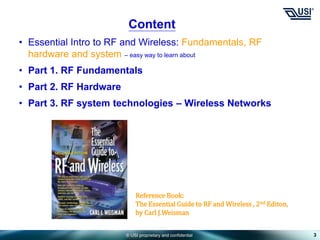
This document serves as an essential introduction to radio frequency (RF) and wireless technology, covering fundamental concepts, RF hardware, and system technologies. Key topics include signal behavior, RF components like antennas and amplifiers, and the principles of RF system design. The document is structured into parts that outline the basic concepts and behaviors of RF, hardware components, and practical examples of applications in wireless communication.
![© USI proprietary and confidential
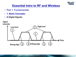
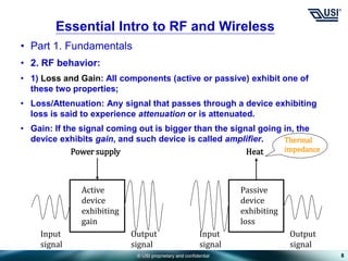
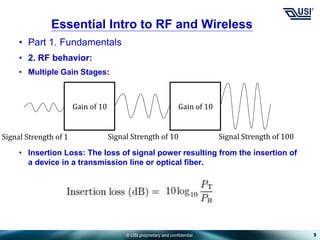
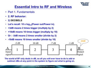
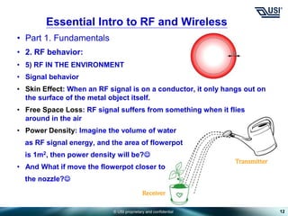
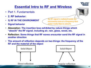
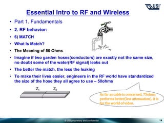
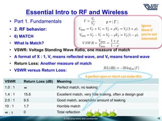
• Part 1. Fundamentals
• 2. RF behavior:
• 3) BANDWIDTH
• Example: If a device can accommodate all frequencies between 75MHz
and 125MHz, what is its band width and percentage bandwidth?
• 125MHz – 75MHz = 50MHz;
• 50MHz ÷ [(125MHz + 75MHz) ÷ 2] × 100% = 50%
• Octaves bandwidth example: 100MHz ~ 200MHz
• Decades bandwidth example: 100MHz ~ 1GHz
• 4) WIDEBAND AND NARROWBAND
• For example: narrowband – bandwidth < 50%; wideband – bandwidth >
50%
• Key: the wider the bandwidth of a component, the more frequencies it
can accommodate, but the more it costs and the worse it performs.
11
Essential Intro to RF and Wireless](https://image.slidesharecdn.com/basicrfintro-240517024333-8d0876ce/85/Basic-RF-introduction-for-newbies-eng-ppt-11-320.jpg)


![Multiband Transceivers - [Chapter 7] Multi-mode/Multi-band GSM/GPRS/TDMA/AMP...](https://cdn.slidesharecdn.com/ss_thumbnails/ch7-150613070936-lva1-app6892-thumbnail.jpg?width=640&height=640&fit=bounds)


![Multiband Transceivers - [Chapter 1]](https://cdn.slidesharecdn.com/ss_thumbnails/ch1-150613070932-lva1-app6891-thumbnail.jpg?width=640&height=640&fit=bounds)