Downloaded 12 times


![ Zero ohm resistors are made as lengths of wire wrapped in
a resistor-shaped body which can be substituted for
another resistor value in automatic insertion equipment.
They are marked with a single black band.[4]
The 'body-end-dot' or 'body-tip-spot' system was used for
radial-lead (and other cylindrical) composition resistors
sometimes still found in very old equipment; the first band
was given by the body color, the second band by the color
of the end of the resistor, and the multiplier by a dot or
band around the middle of the resistor. The other end of
the resistor was colored gold or silver to give the tolerance,
otherwise it was 20%.[5]
](https://image.slidesharecdn.com/workexperiencepowerpoint-160128121237/75/Work-experience-power-point-9-2048.jpg)


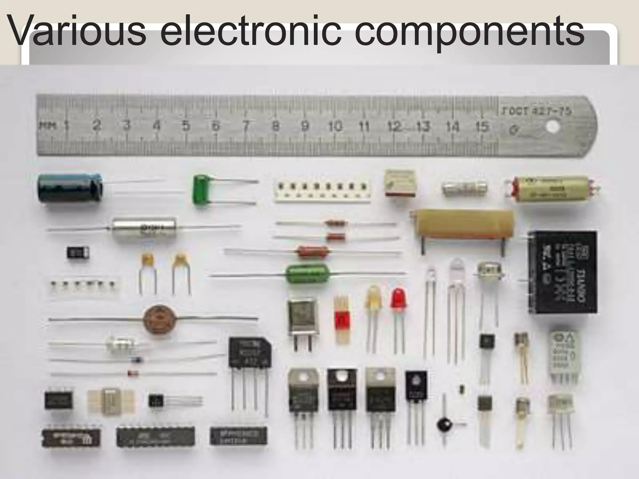


![ Active components rely on a source of
energy (usually from the DC circuit, which
we have chosen to ignore) and usually
can inject power into a circuit, though this
is not part of the definition.[1] Active
components include amplifying
components such as transistors,
triode vacuum tubes (valves), and tunnel
diodes.](https://image.slidesharecdn.com/workexperiencepowerpoint-160128121237/75/Work-experience-power-point-18-2048.jpg)


The document discusses various electronic components including resistors, their color coding, and resistor combinations. It explains that resistors use preferred values in the E12, E24, and E6 series that are related to the root of 10 and repeat per decade. It also describes how to read color bands on resistors to determine values and tolerances. Resistors can be connected in series or parallel combinations, with the total resistance calculated using standard formulas. Finally, it provides a broad overview of common electronic components and how they are classified as active, passive or electromechanical based on their ability to introduce or rely on external power sources.