6.2
Bandwidth utilization isthe wise use of
available bandwidth to achieve
specific goals.
Efficiency can be achieved by
multiplexing; i.e., sharing of the
bandwidth between multiple users.
3.
6.3
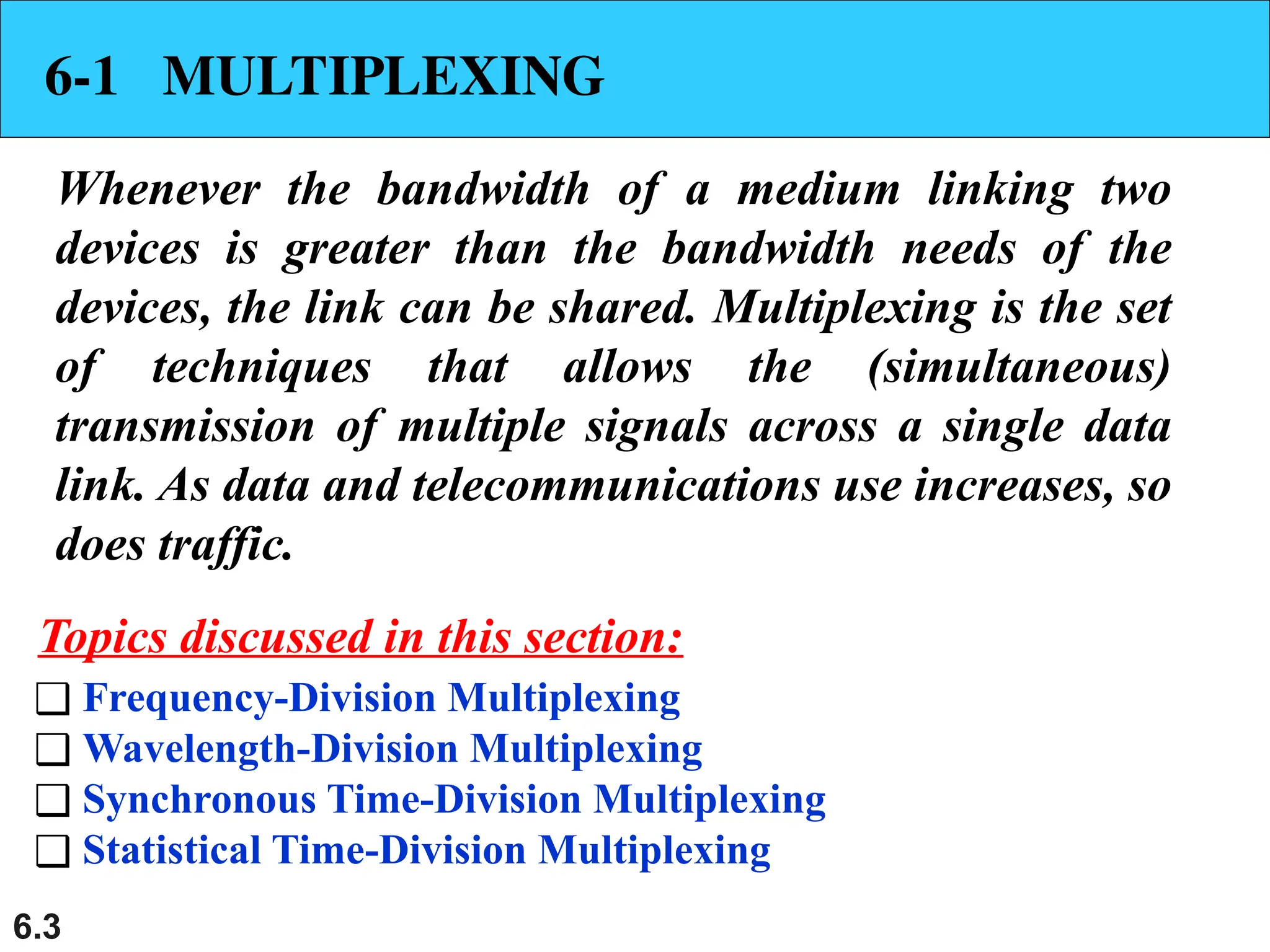
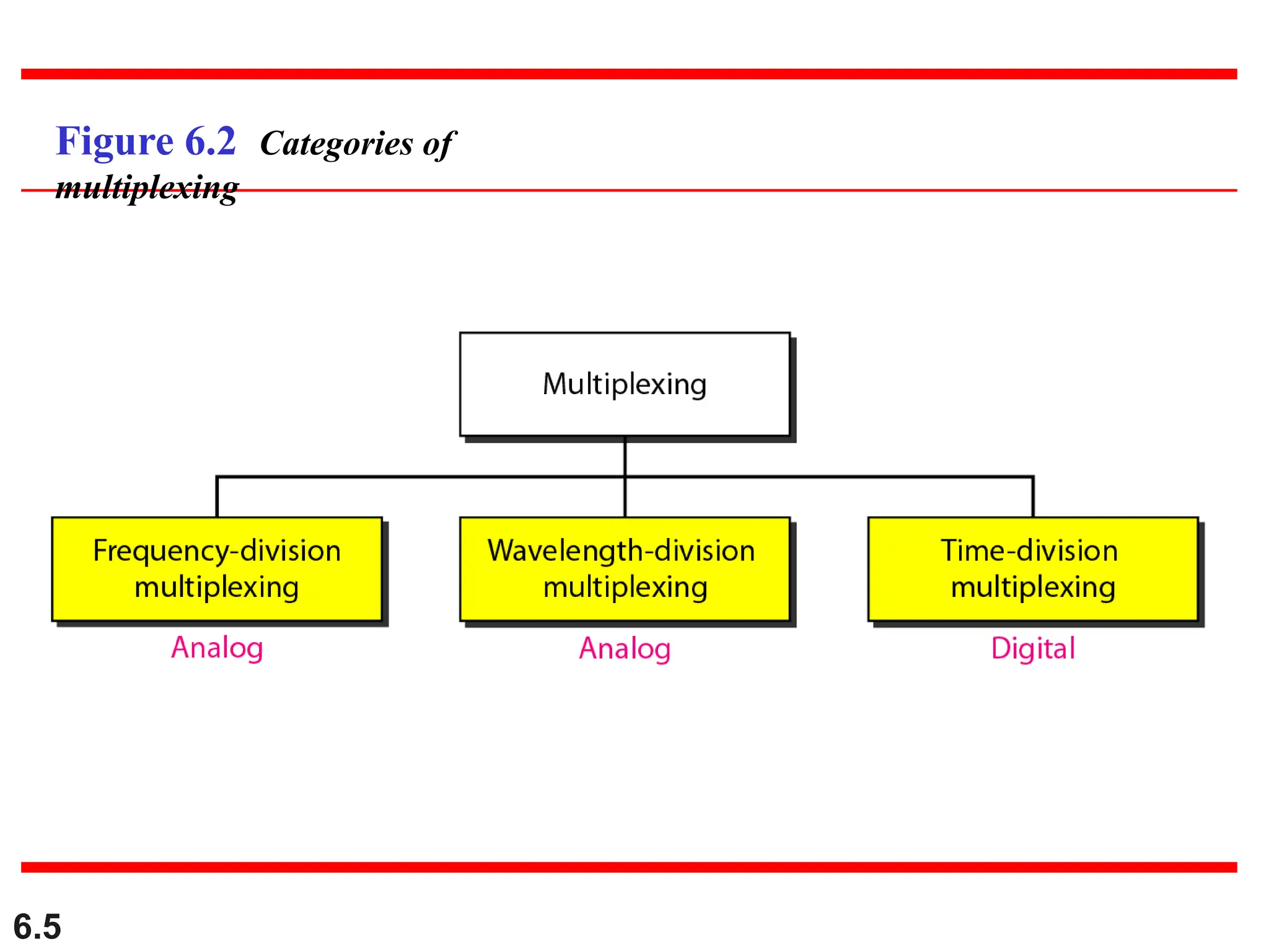
6-1 MULTIPLEXING
Whenever thebandwidth of a medium linking two
devices is greater than the bandwidth needs of the
devices, the link can be shared. Multiplexing is the set
of techniques that allows the (simultaneous)
transmission of multiple signals across a single data
link. As data and telecommunications use increases, so
does traffic.
❑ Frequency-Division Multiplexing
❑ Wavelength-Division Multiplexing
❑ Synchronous Time-Division Multiplexing
❑ Statistical Time-Division Multiplexing
Topics discussed in this section:
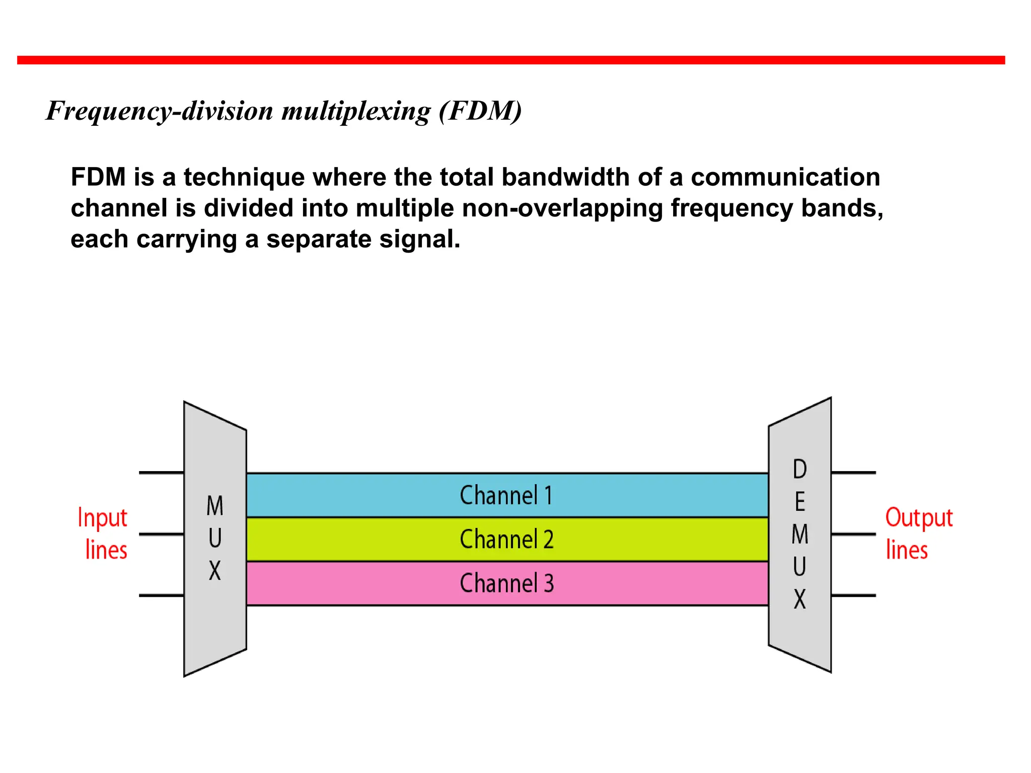
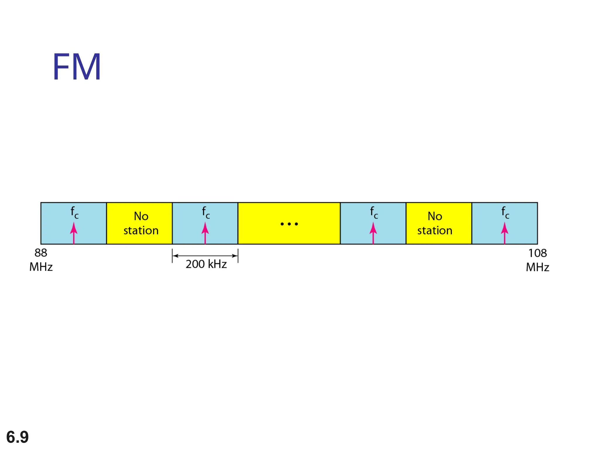
Frequency-division multiplexing (FDM)
FDMis a technique where the total bandwidth of a communication
channel is divided into multiple non-overlapping frequency bands,
each carrying a separate signal.
7.
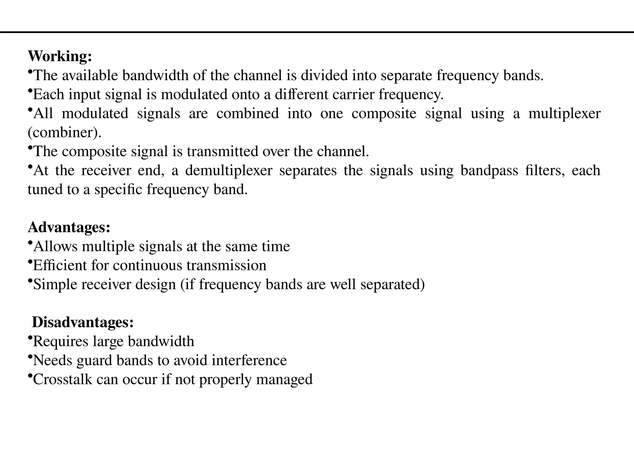
Working:
•The available bandwidthof the channel is divided into separate frequency bands.
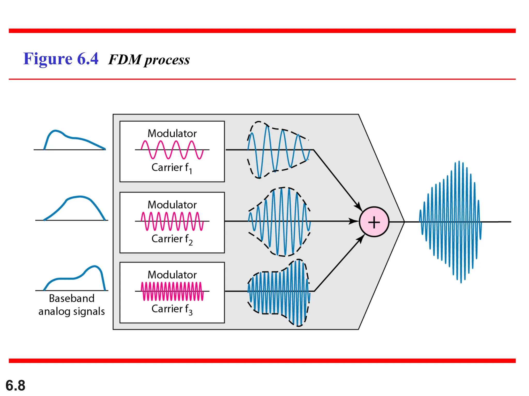
•Each input signal is modulated onto a different carrier frequency.
•All modulated signals are combined into one composite signal using a multiplexer
(combiner).
•The composite signal is transmitted over the channel.
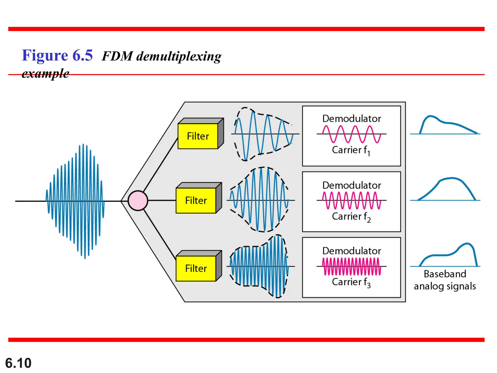
•At the receiver end, a demultiplexer separates the signals using bandpass filters, each
tuned to a specific frequency band.
Advantages:
•Allows multiple signals at the same time
•Efficient for continuous transmission
•Simple receiver design (if frequency bands are well separated)
Disadvantages:
•Requires large bandwidth
•Needs guard bands to avoid interference
•Crosstalk can occur if not properly managed
6.11
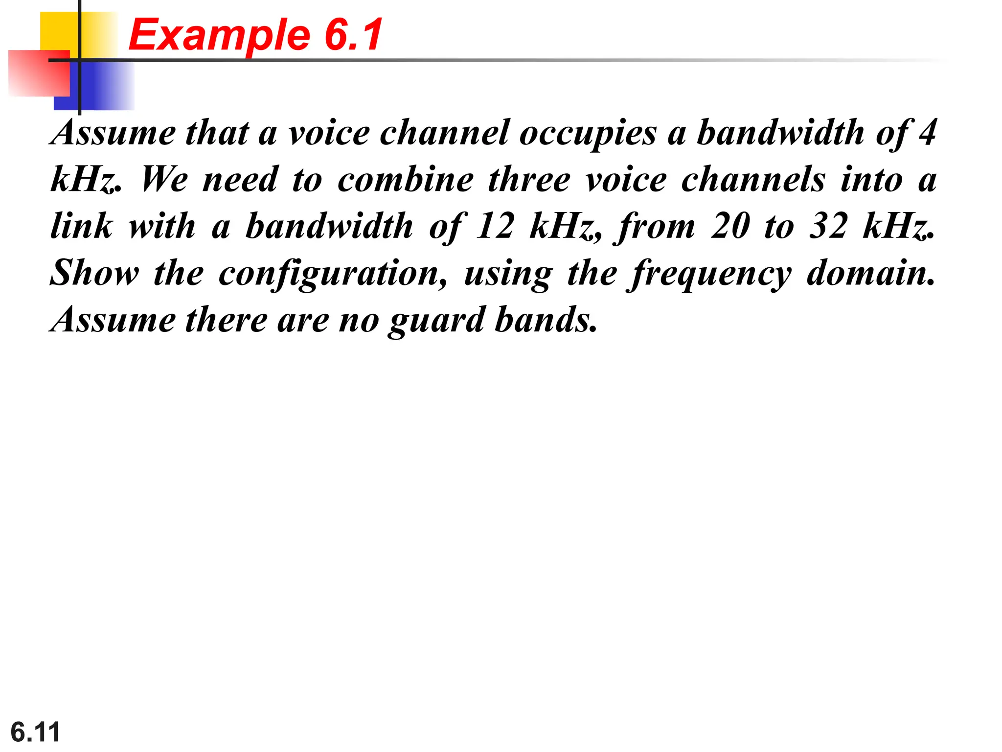
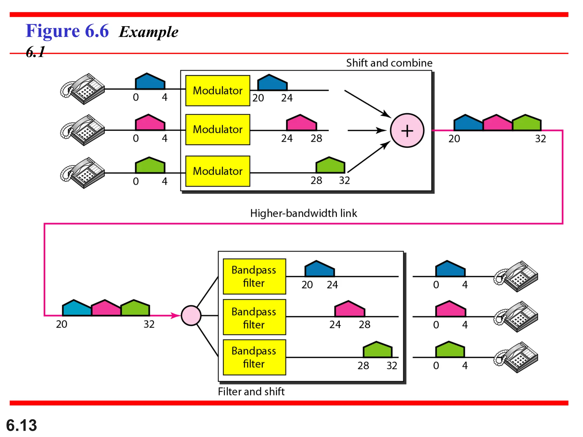
Assume that avoice channel occupies a bandwidth of 4
kHz. We need to combine three voice channels into a
link with a bandwidth of 12 kHz, from 20 to 32 kHz.
Show the configuration, using the frequency domain.
Assume there are no guard bands.
Example 6.1
12.
6.12
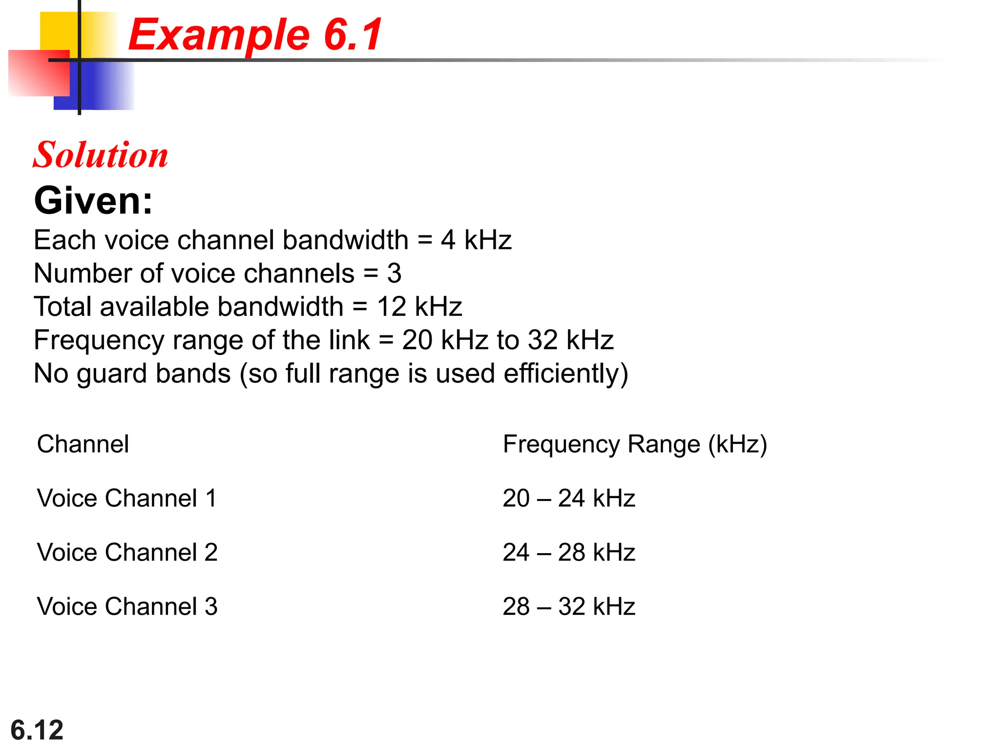
Solution
Given:
Each voice channelbandwidth = 4 kHz
Number of voice channels = 3
Total available bandwidth = 12 kHz
Frequency range of the link = 20 kHz to 32 kHz
No guard bands (so full range is used efficiently)
Example 6.1
Channel Frequency Range (kHz)
Voice Channel 1 20 – 24 kHz
Voice Channel 2 24 – 28 kHz
Voice Channel 3 28 – 32 kHz
6.14
Five channels, eachwith a 100-kHz bandwidth, are to be
multiplexed together. What is the minimum bandwidth of
the link if there is a need for a guard band of 10 kHz
between the channels to prevent interference?
Example 6.2
15.
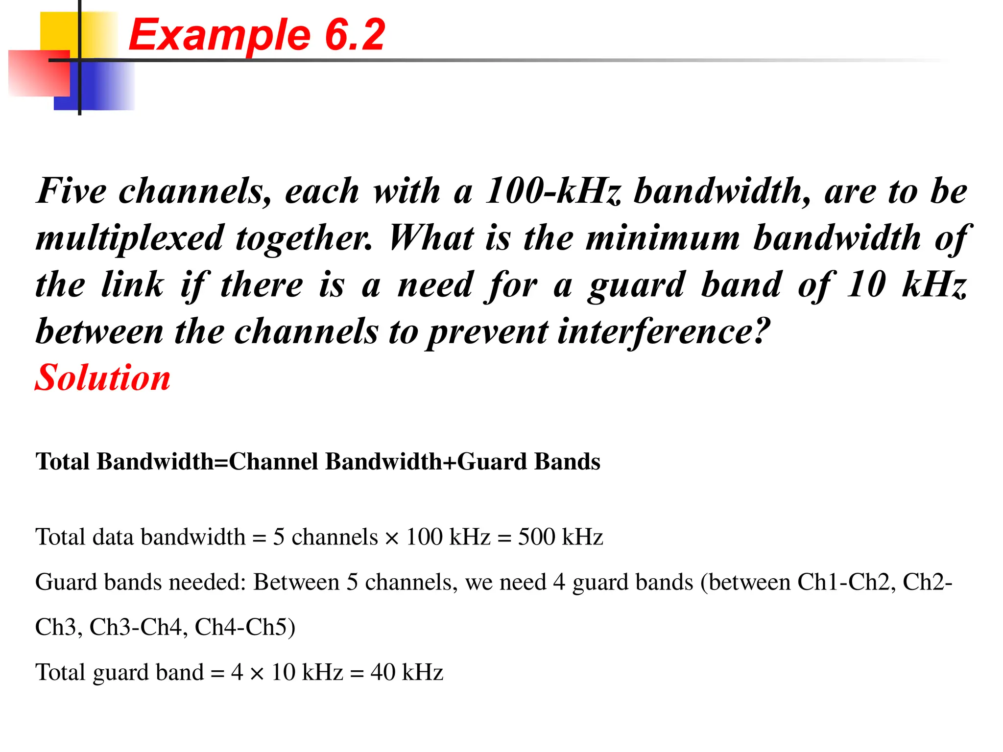
Five channels, eachwith a 100-kHz bandwidth, are to be
multiplexed together. What is the minimum bandwidth of
the link if there is a need for a guard band of 10 kHz
between the channels to prevent interference?
Solution
Total Bandwidth=Channel Bandwidth+Guard Bands
Total data bandwidth = 5 channels × 100 kHz = 500 kHz
Guard bands needed: Between 5 channels, we need 4 guard bands (between Ch1-Ch2, Ch2-
Ch3, Ch3-Ch4, Ch4-Ch5)
Total guard band = 4 × 10 kHz = 40 kHz
Example 6.2
16.
6.16
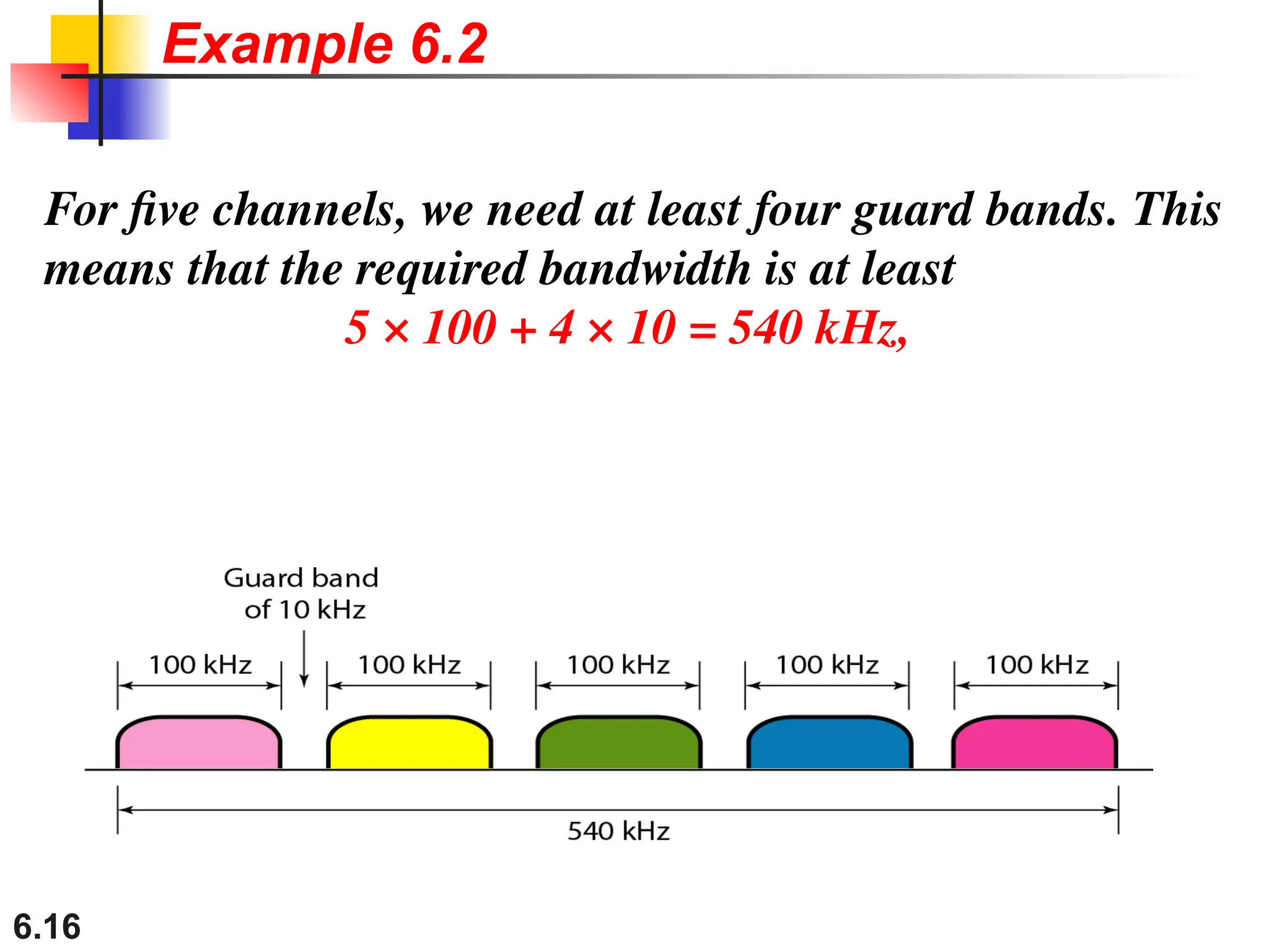
For five channels,we need at least four guard bands. This
means that the required bandwidth is at least
5 × 100 + 4 × 10 = 540 kHz,
Example 6.2
17.
6.17
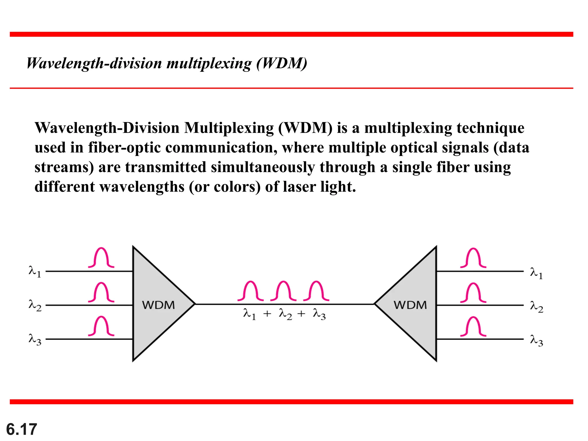
Wavelength-division multiplexing (WDM)
Wavelength-DivisionMultiplexing (WDM) is a multiplexing technique
used in fiber-optic communication, where multiple optical signals (data
streams) are transmitted simultaneously through a single fiber using
different wavelengths (or colors) of laser light.
18.
6.18
Advantages:
1.Maximizes fiber bandwidthutilization.
2.Enables scalable network growth.
3.Supports bi-directional communication over the same fiber.
4.No interference between channels (due to different λ).
Application Areas:
•Internet backbone and metro networks.
•Long-haul telecom networks.
•Data centers and cloud computing.
•Cable TV transmission.
6.20
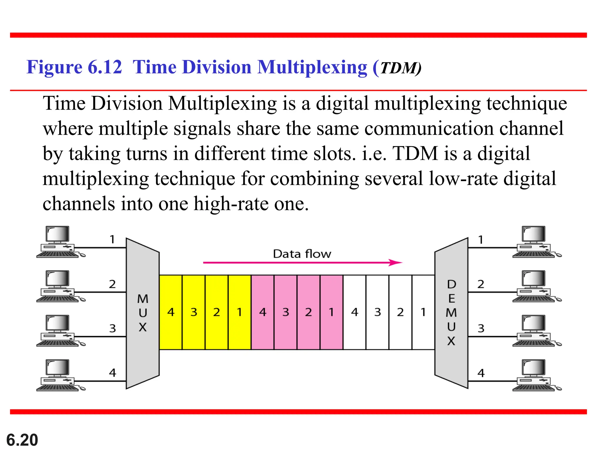
Figure 6.12 TimeDivision Multiplexing (TDM)
Time Division Multiplexing is a digital multiplexing technique
where multiple signals share the same communication channel
by taking turns in different time slots. i.e. TDM is a digital
multiplexing technique for combining several low-rate digital
channels into one high-rate one.
21.
6.21
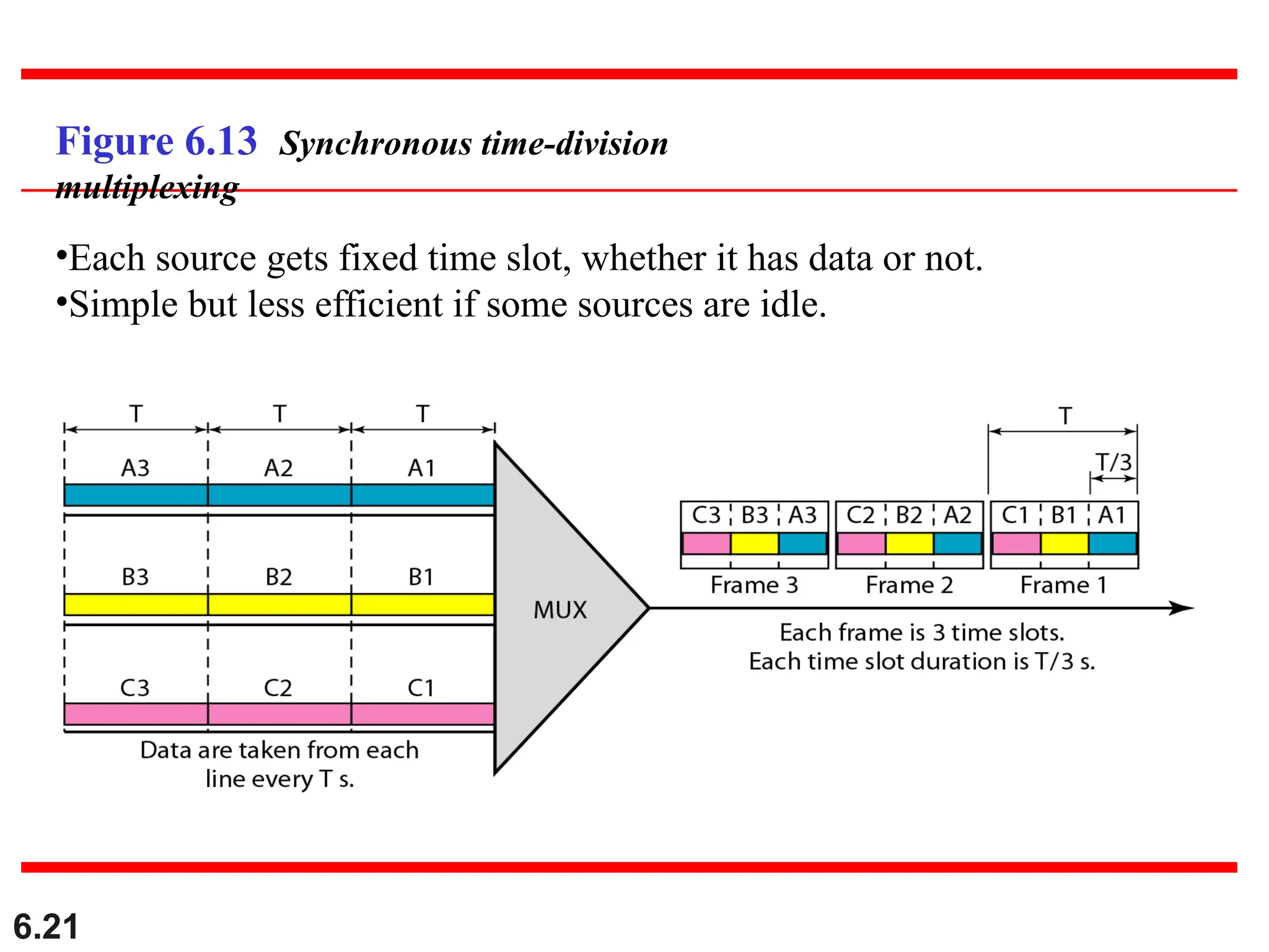
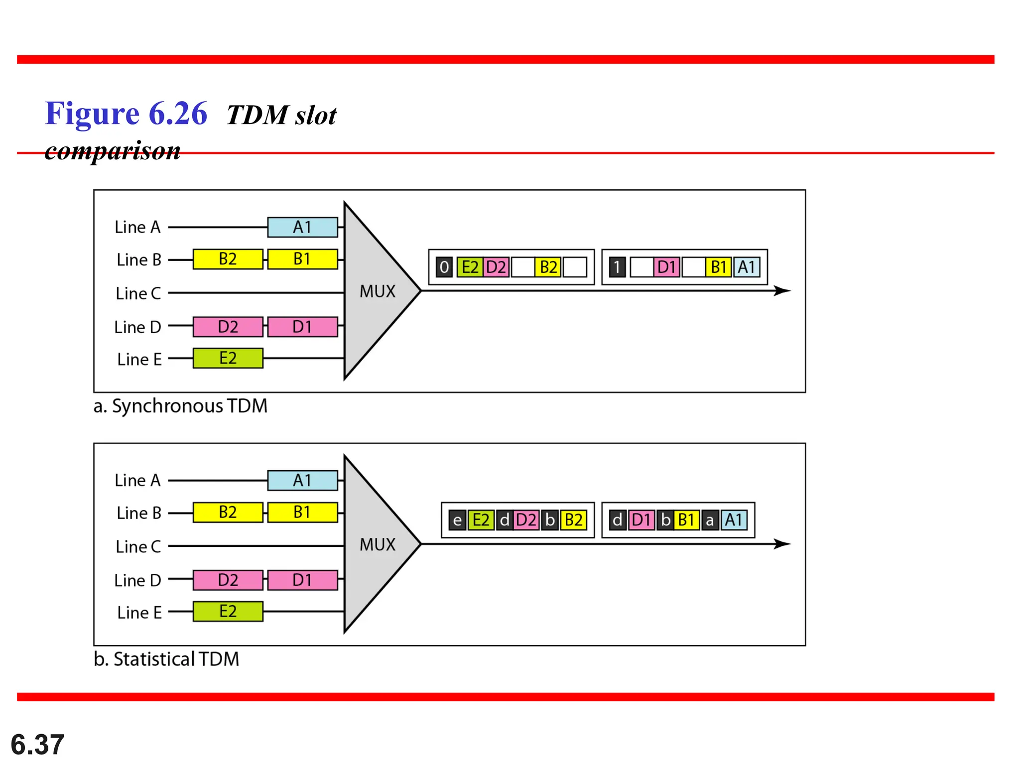
Figure 6.13 Synchronoustime-division
multiplexing
•Each source gets fixed time slot, whether it has data or not.
•Simple but less efficient if some sources are idle.
22.
6.22
Advantages:
No interference betweensignals.
Fully digital, easy to implement with modern electronics.
Can be used with both analog and digital signals.
Disadvantages:
Needs precise synchronization.
Not efficient in synchronous TDM if users are idle.
Delay may occur if many users are transmitting.
Applications:
Digital telephony systems (e.g., E1/T1 lines)
Satellite communication
Multiplexing audio/video streams
4G/5G networks (as part of hybrid systems)
23.
6.23
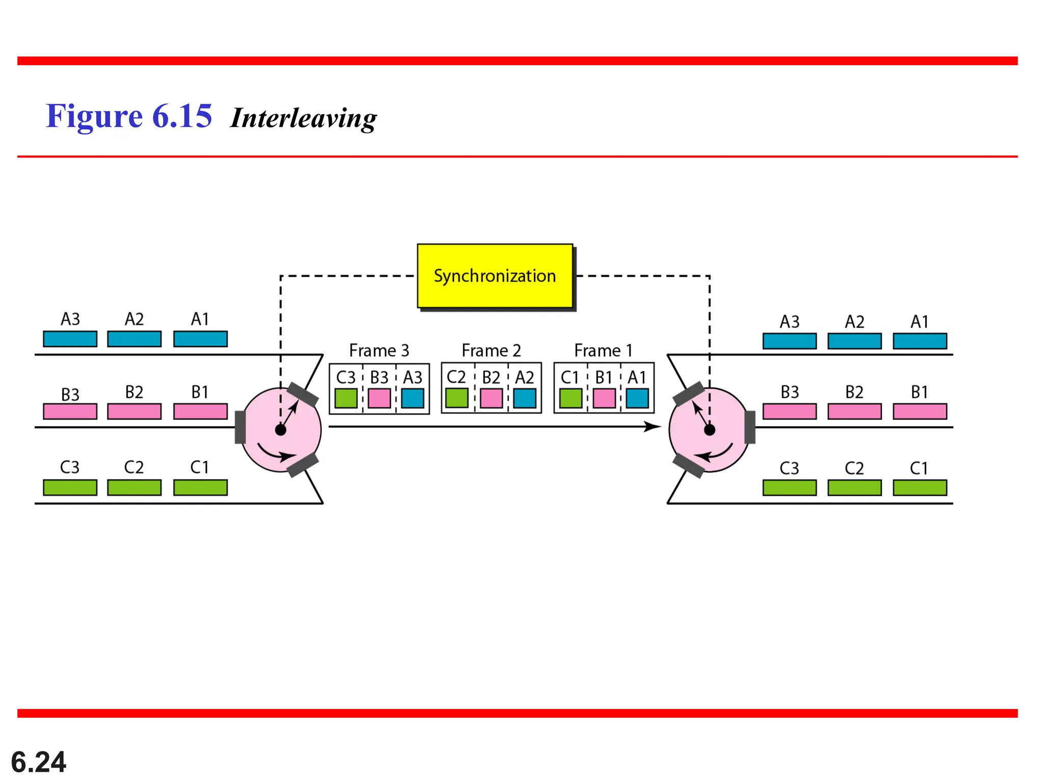
Interleaving
■The process oftaking a group of bits
from each input line for multiplexing
is called interleaving.
■We interleave bits (1 - n) from each
input onto one output.
6.26
Data Rate Management
■Notall input links maybe have the
same data rate.
■Some links maybe slower. There
maybe several different input link
speeds
■There are three strategies that can be
used to overcome the data rate
mismatch: multilevel, multislot and
pulse stuffing
27.
6.27
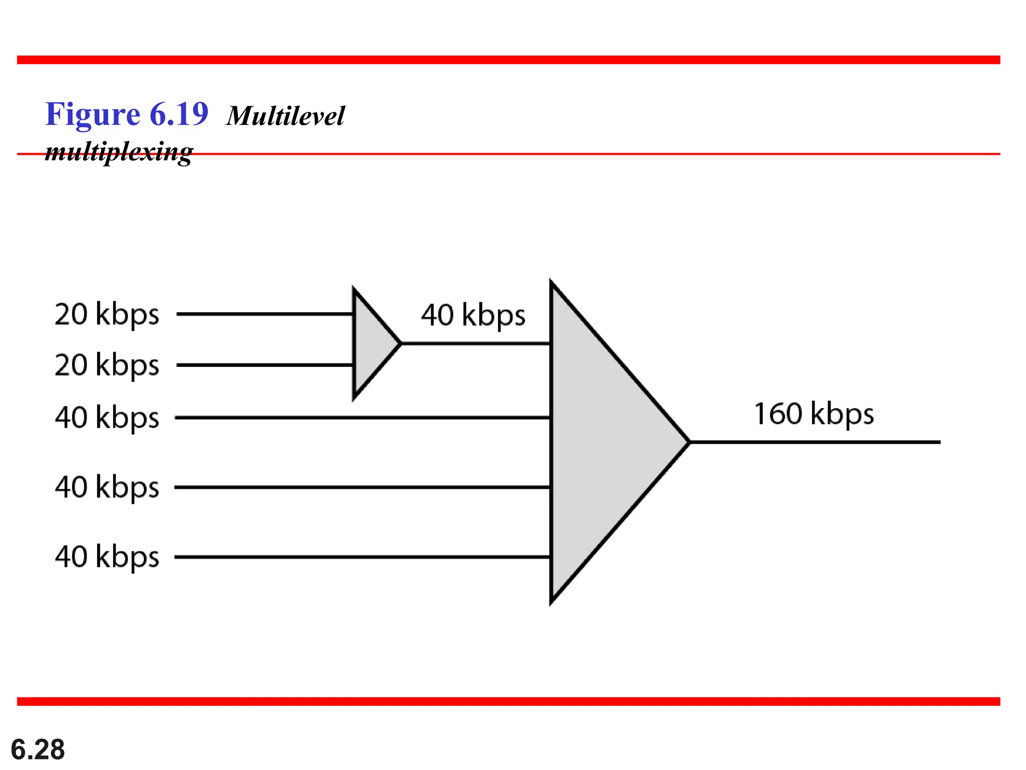
Data rate matching
■Multilevel:used when the data rate of the
input links are multiples of each other.
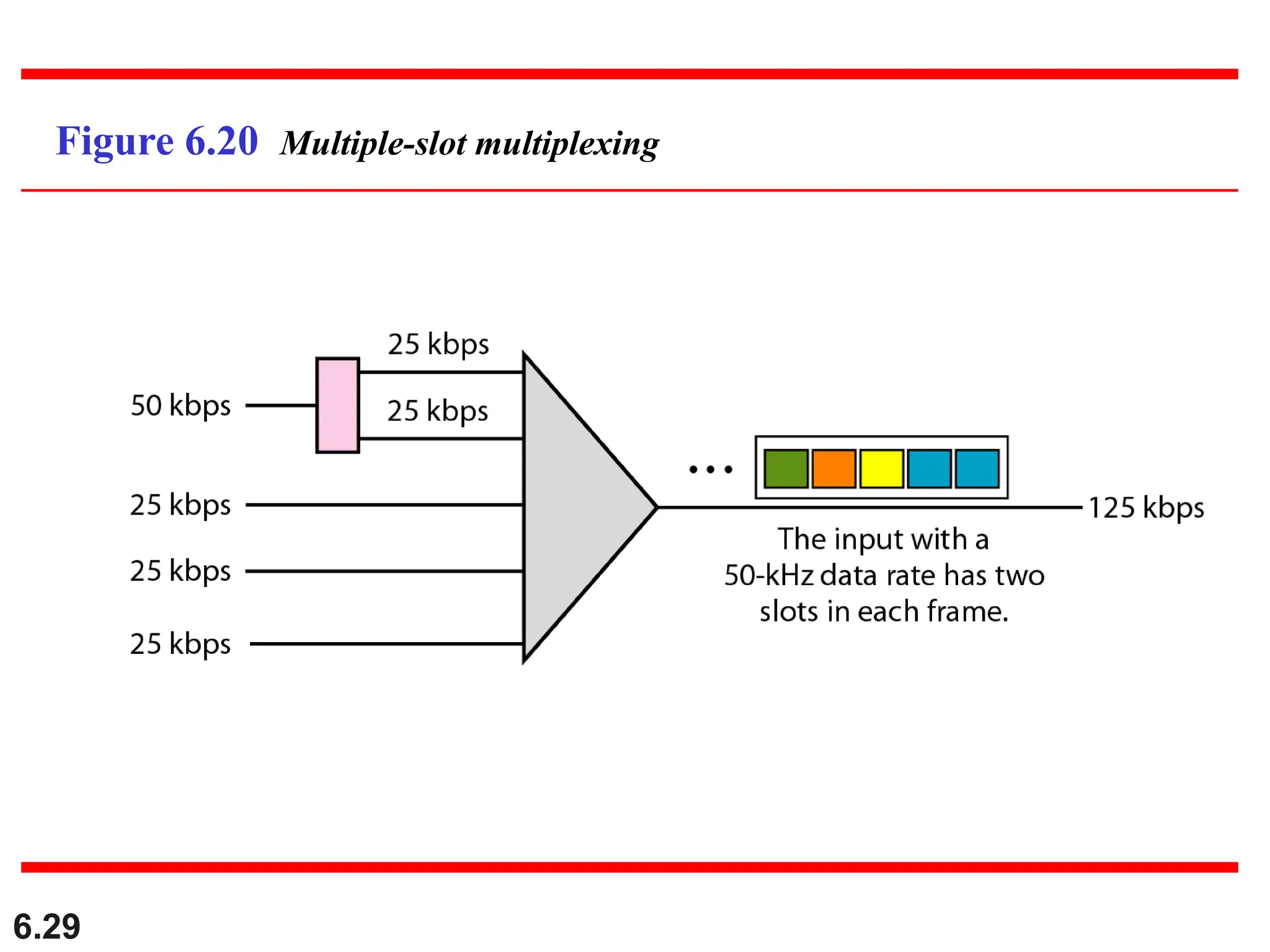
■Multislot: used when there is a GCD
between the data rates. The higher bit rate
channels are allocated more slots per
frame, and the output frame rate is a
multiple of each input link.
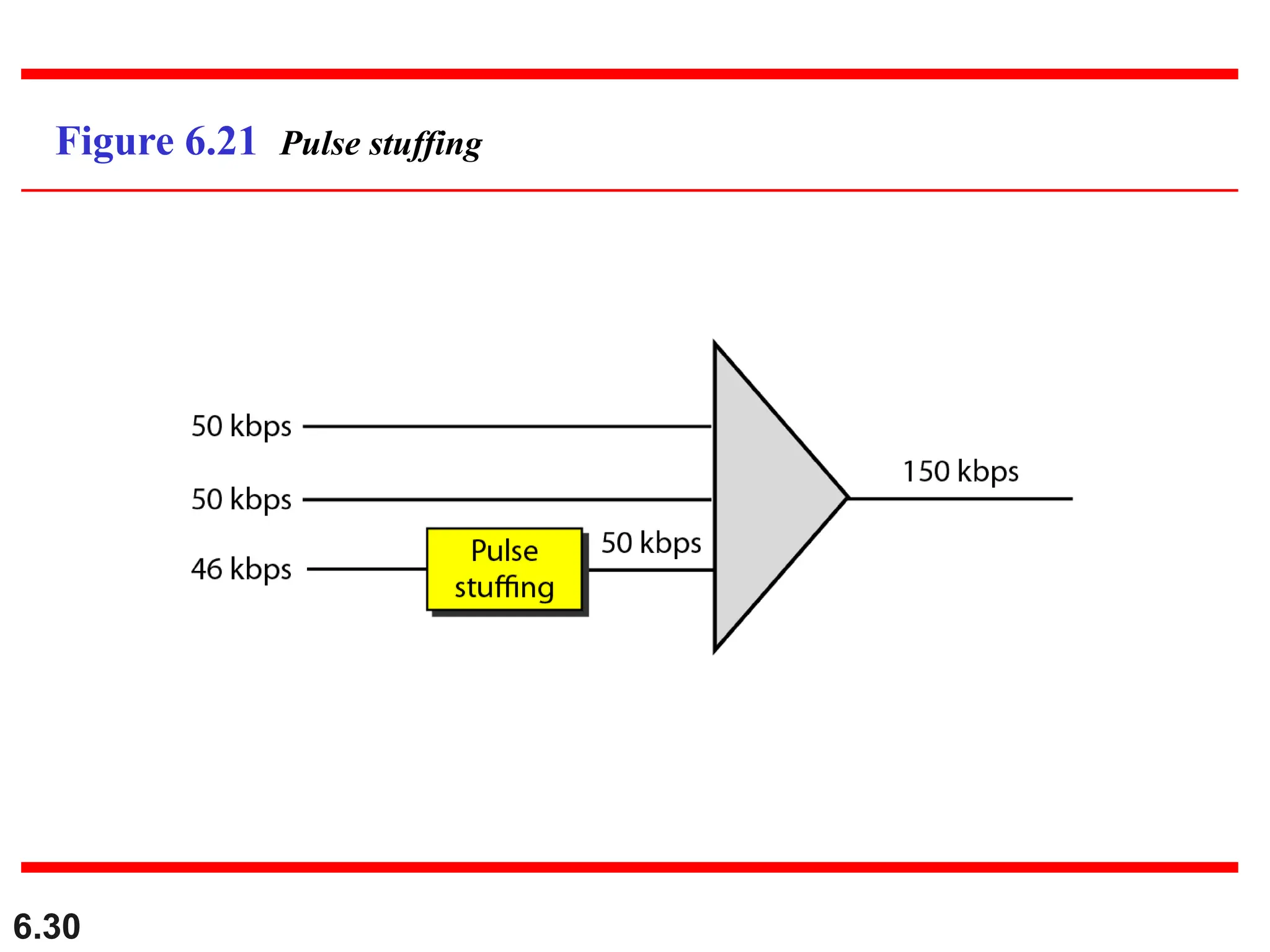
■Pulse Stuffing: used when there is no GCD
between the links. The slowest speed link
will be brought up to the speed of the
other links by bit insertion, this is called
pulse stuffing.
6.31
Synchronization
■To ensure thatthe receiver correctly reads the
incoming bits, i.e., knows the incoming bit
boundaries to interpret a “1” and a “0”, a known
bit pattern is used between the frames.
■The receiver looks for the anticipated bit and starts
counting bits till the end of the frame.
■Then it starts over again with the reception of
another known bit.
■These bits (or bit patterns) are called
synchronization bit(s).
■They are part of the overhead of transmission.
6.33
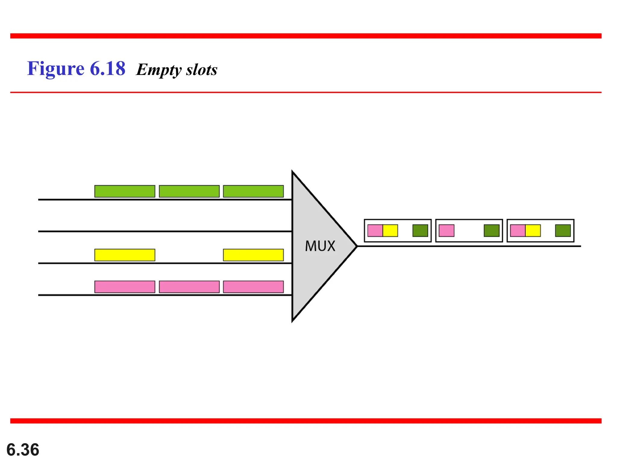
Inefficient use ofBandwidth
■Sometimes an input link may have no
data to transmit.
■When that happens, one or more
slots on the output link will go
unused.
■That is wasteful of bandwidth.
34.
6.34
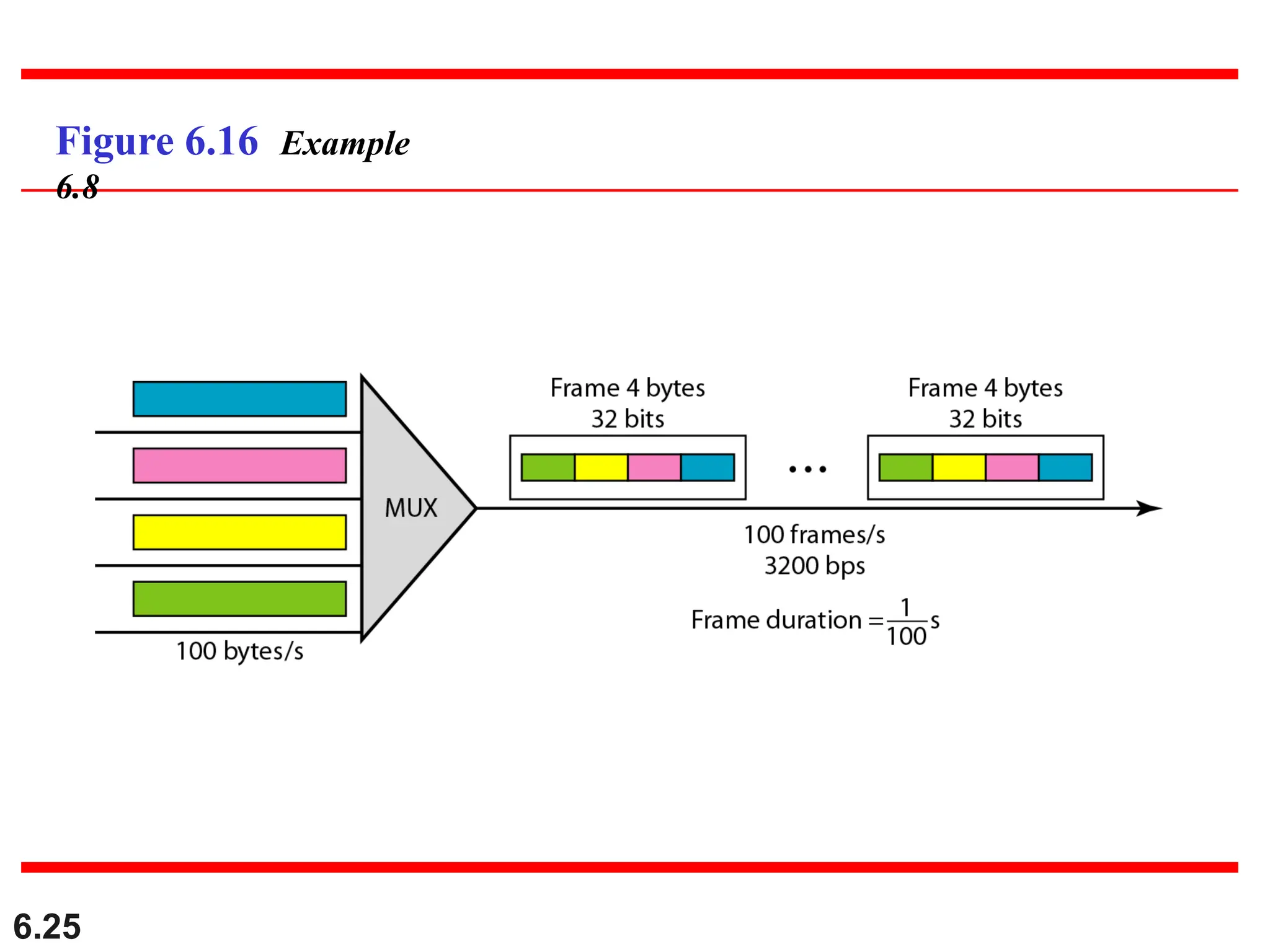
We have foursources, each creating 250 8-bit characters
per second. If the interleaved unit is a character and 1
synchronizing bit is added to each frame, find (a) the data
rate of each source, (b) the duration of each character in
each source, (c) the frame rate, (d) the duration of each
frame, (e) the number of bits in each frame, and (f) the
data rate of the link.
Example 6.10
35.
6.35
Two channels, onewith a bit rate of 100 kbps and
another with a bit rate of 200 kbps, are to be multiplexed.
How this can be achieved? What is the frame rate? What
is the frame duration? What is the bit rate of the link?
Example 6.11
6.38
In Figure 6.13,the data rate for each one of the 3 input
connection is 1 kbps. If 1 bit at a time is multiplexed (a
unit is 1 bit), what is the duration of (a) each input slot,
(b) each output slot, and (c) each frame?
Example 6.5
39.
6.39
Solution
We can answerthe questions as follows:
a. The data rate of each input connection is 1 kbps. This
means that the bit duration is 1/1000 s or 1 ms. The
duration of the input time slot is 1 ms (same as bit
duration).
Example 6.5
40.
6.40
b. The durationof each output time slot is one-third of
the input time slot. This means that the duration of the
output time slot is 1/3 ms.
c. Each frame carries three output time slots. So the
duration of a frame is 3 × 1/3 ms, or 1 ms.
Note: The duration of a frame is the same as the duration
of an input unit.
Example 6.5 (continued)
41.
6.41
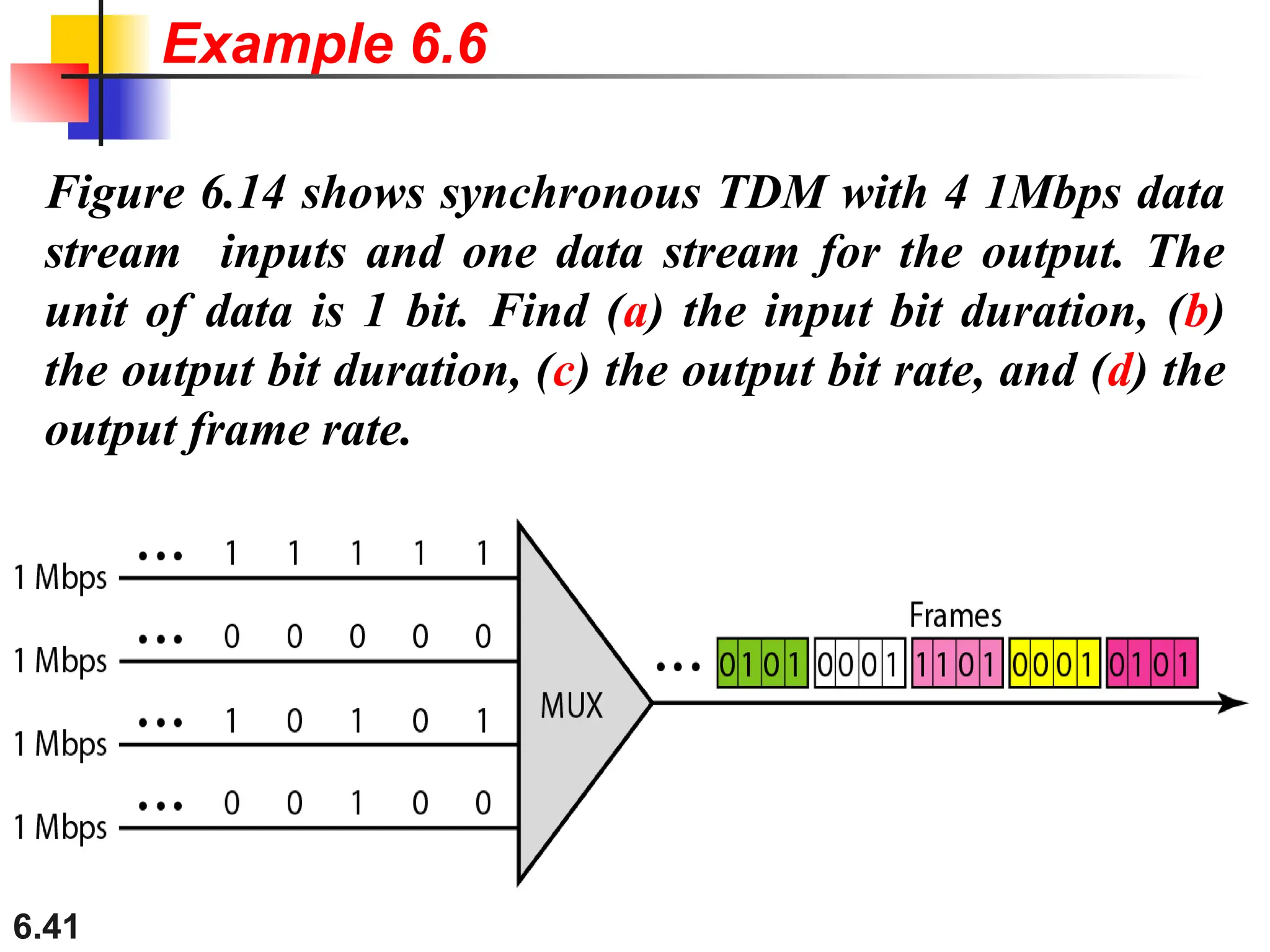
Figure 6.14 showssynchronous TDM with 4 1Mbps data
stream inputs and one data stream for the output. The
unit of data is 1 bit. Find (a) the input bit duration, (b)
the output bit duration, (c) the output bit rate, and (d) the
output frame rate.
Example 6.6
42.
6.42
Solution
We can answerthe questions as follows:
a. The input bit duration is the inverse of the bit rate:
1/1 Mbps = 1 μs.
b. The output bit duration is one-fourth of the input bit
duration, or ¼ μs.
Example 6.6
43.
6.43
c. The outputbit rate is the inverse of the output bit
duration or 1/(4μs) or 4 Mbps. This can also be
deduced from the fact that the output rate is 4 times as
fast as any input rate; so the output rate = 4 × 1 Mbps
= 4 Mbps.
d. The frame rate is always the same as any input rate. So
the frame rate is 1,000,000 frames per second.
Because we are sending 4 bits in each frame, we can
verify the result of the previous question by
multiplying the frame rate by the number of bits per
frame.
Example 6.6 (continued)
44.
6.44
Four 1-kbps connectionsare multiplexed together. A unit
is 1 bit. Find (a) the duration of 1 bit before multiplexing,
(b) the transmission rate of the link, (c) the duration of a
time slot, and (d) the duration of a frame.
Example 6.7
45.
6.45
Solution
We can answerthe questions as follows:
a. The duration of 1 bit before multiplexing is 1 / 1 kbps,
or 0.001 s (1 ms).
b. The rate of the link is 4 times the rate of a connection,
or 4 kbps.
Example 6.7
46.
6.46
c. The durationof each time slot is one-fourth of the
duration of each bit before multiplexing, or 1/4 ms or
250 μs. Note that we can also calculate this from the
data rate of the link, 4 kbps. The bit duration is the
inverse of the data rate, or 1/4 kbps or 250 μs.
d. The duration of a frame is always the same as the
duration of a unit before multiplexing, or 1 ms. We
can also calculate this in another way. Each frame in
this case has four time slots. So the duration of a
frame is 4 times 250 μs, or 1 ms.
Example 6.7
(continued)
47.
6.47
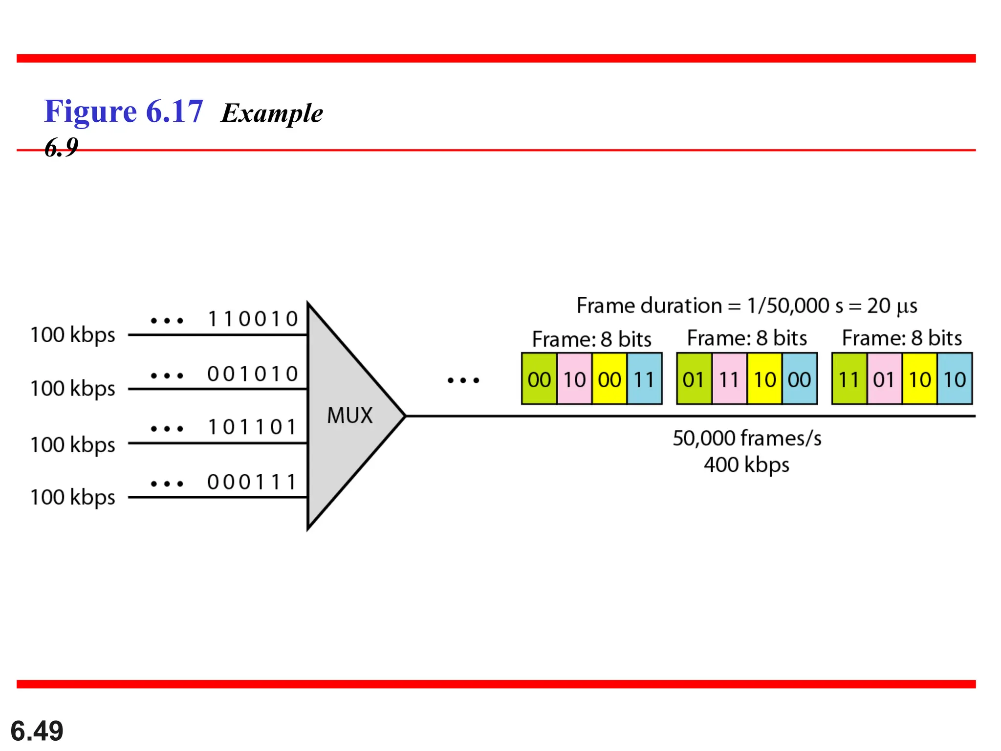
A multiplexer combinesfour 100-kbps channels using a
time slot of 2 bits. Show the output with four arbitrary
inputs. What is the frame rate? What is the frame
duration? What is the bit rate? What is the bit duration?
Example 6.9
48.
6.48
Solution
Figure 6.17 showsthe output (4x100kbps) for four
arbitrary inputs. The link carries 400K/(2x4)=50,000
2x4=8bit frames per second. The frame duration is
therefore 1/50,000 s or 20 μs. The bit duration on the
output link is 1/400,000 s, or 2.5 μs.
Example 6.9