Downloaded 90 times
![Reference
[Online].Available: https://learn.adafruit.com/setting-up-a-raspberry-pi-as-a-wifi-
accesspoint
[Online].Available: https://blog.bitify.co.uk/2013/11/reading-data-from-mpu-6050-
on-raspberry.html
[Online].Available: https://www.raspberrypi.org/documentation
[Online].Available: https://github.com/vjaunet/QUADCOPTER_V2
[Online].Available: https://github.com/vjaunet/QUADCOPTER
[Online].Available: https://www.dropbox.com/sh/yu5a21jszu9l56i/auMp69raLM
[Online].Available: https://en.m.Wikipedia.org/](https://image.slidesharecdn.com/autonomousdroneprojectpart1-170427101037/75/Autonomous-drone-project-part-1-16-2048.jpg)

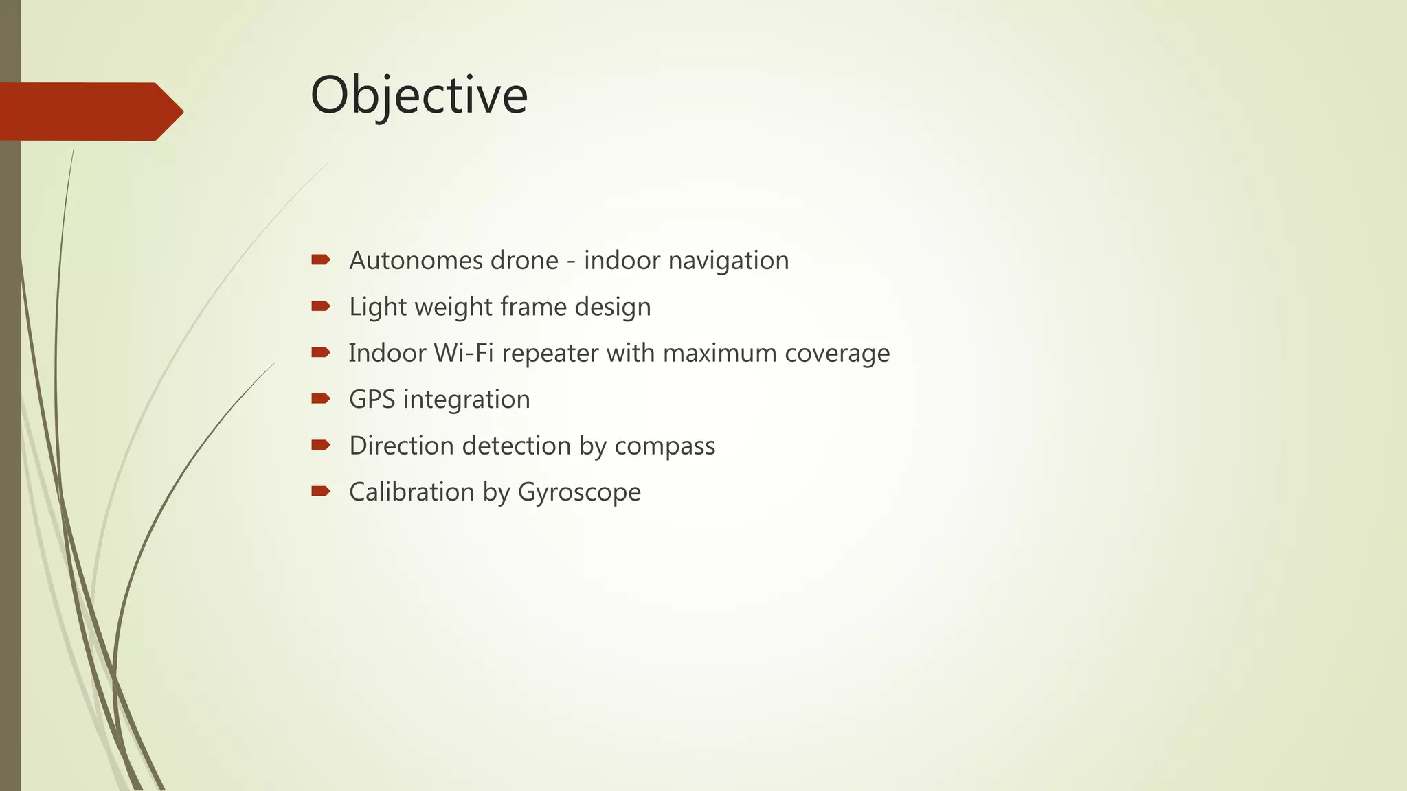
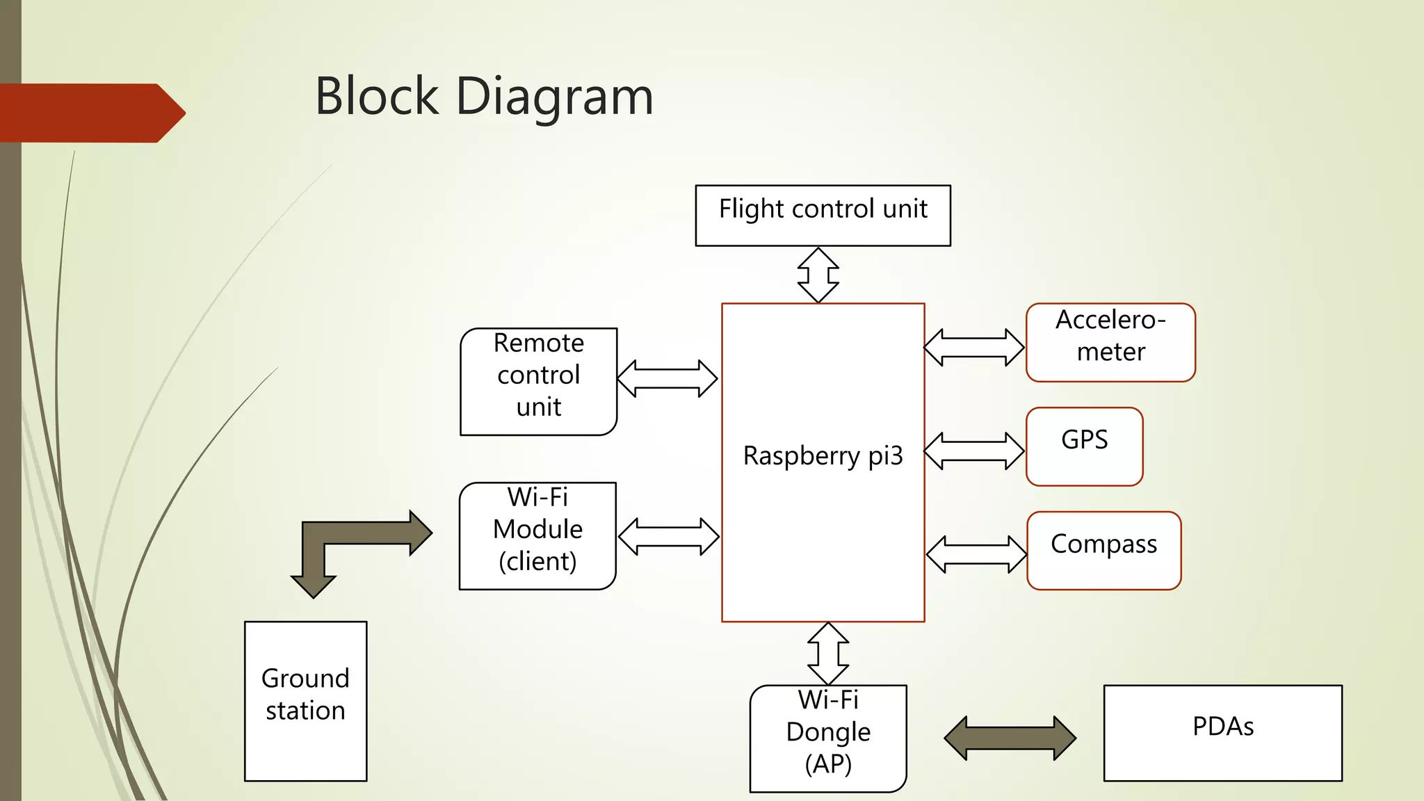
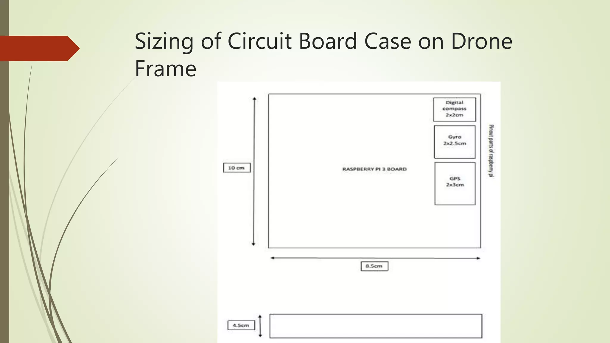
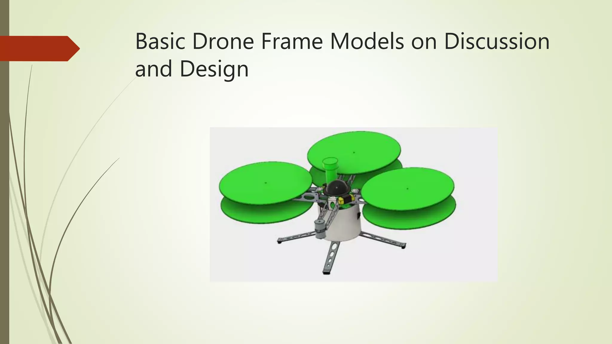
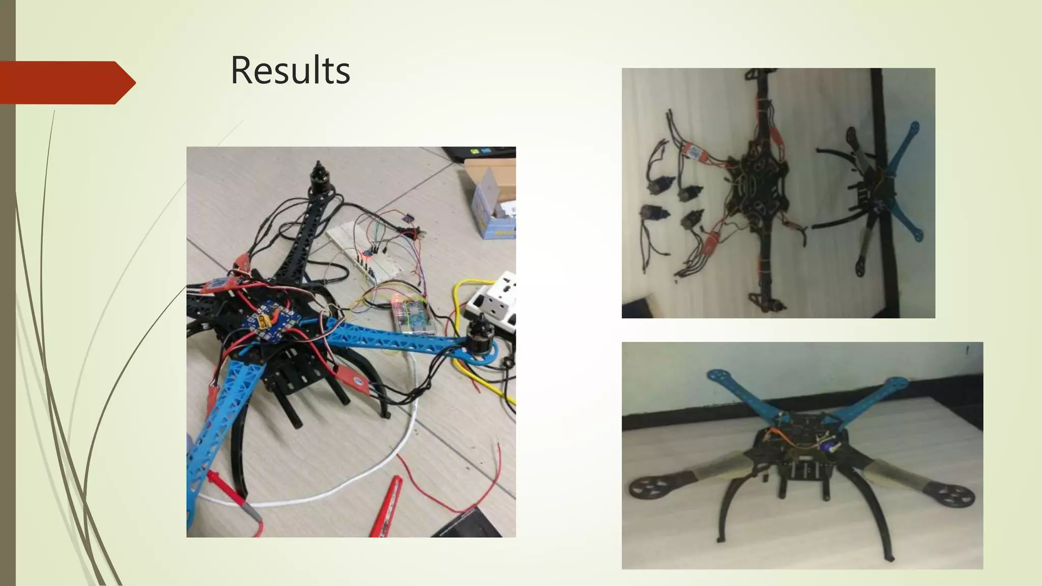
This document outlines an autonomous drone project focusing on indoor navigation, featuring a lightweight design, GPS integration, and various sensors for directional detection. Key components include a Raspberry Pi for flight control, electronic speed controllers, and a lithium polymer battery system for power. The project emphasizes the importance of accurate sensor calibration and includes various resources for further information.


![Vibe Coding vs. Spec-Driven Development [Free Meetup]](https://cdn.slidesharecdn.com/ss_thumbnails/vibecodingvsspecdrivendevelopment-251209105622-43f455e7-thumbnail.jpg?width=640&height=640&fit=bounds)


