Download as PDF, PPTX
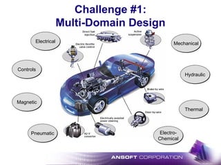
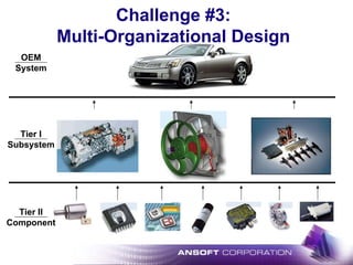
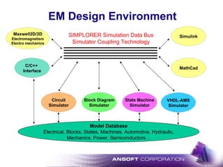
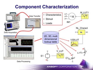
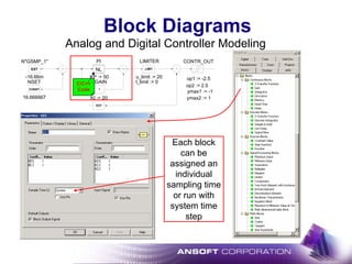
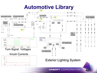

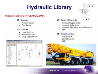
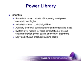
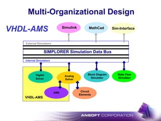
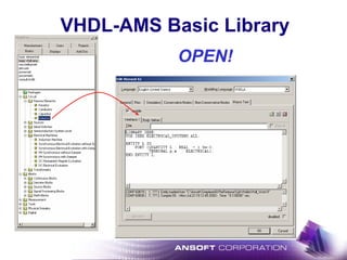
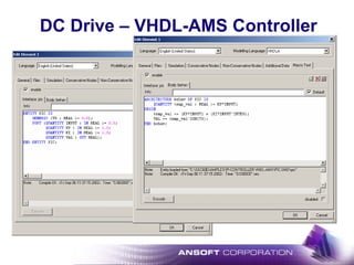
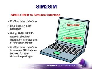
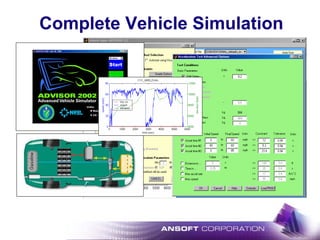
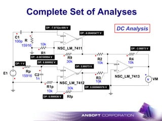
![VHDL-AMS Multi Domain Design
L
dia := 1
len := 1/4
rho := MATH_PI
vol := 1
b := 1
k := 10
EQU
crank_radius:= 0.2
pipe_area:= 0.05
Fluidic
torque force pressure
flow_meter rhyd1 lhyd1
chyd1
spring_rotb damp_rotb T
fm_rotb
ω
+
vm_rotb
ω
+
v_rotb
mass_rotb
CONST CONST
1/pipe_areacrank_radius
P
Spped
damp_rotb.omega
t [s]
40
-40
0
-25
25
0 0.1k50
QuickGraph2
flow_meter.q
t [s]
1Meg
-1Meg
0
0 0.1k50
Mechanic](https://image.slidesharecdn.com/automotiveelectricalandelectromechanicalsystemdesign-130601172124-phpapp02/85/Automotive-electrical-and-electromechanical-system-design-42-320.jpg)
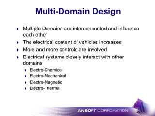
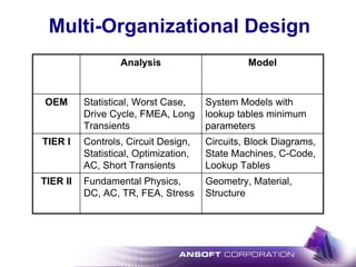
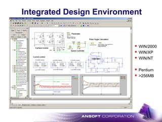
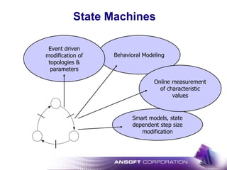
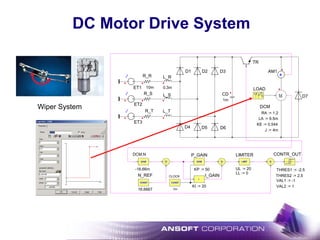
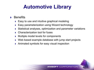
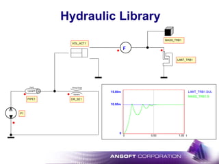
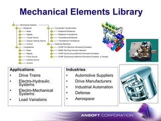
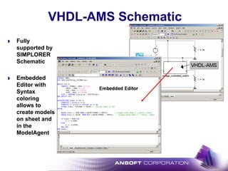
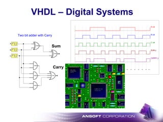
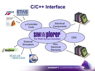
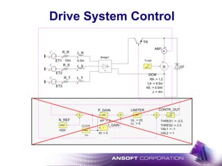
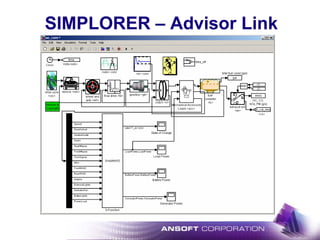
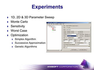
![DC Drive – VHDL-AMS Controller
L_R
0.3m
L_S
L_T
ET1
ET2
ET3
R_R
10m
R_S
R_T
t [s]
4.00e+001
0
2.00e+001
0
0
0.2
0.2
0.1
0.1
t [s]
1.50e+003
0
1.00e+003
0
0
0.2
0.2
0.1
0.1
motor
current
speed and
reference speed
LIMIT
LIMITER
LL := 0
UL := 20
GAIN
CONTR_OUT
THRES1 := -2.5
VAL1 := -1
THRES2 := 2.5
VAL2 := 1
CONST
N_REF
1000
M
DCM
J := 4m
LA := 9.5m
RA := 1.2
KE := 0.544
A
AM1
t [s]
1.00e+003
0
5.00e+002
0
0
0.2
0.2
0.1
0.1
DCM.MI [N·m]
TLoad.VAL
t [s]
2.00e+001
-1.00e+001
0
0
0
0.2
0.2
0.1
0.1
motor torque
and
load torque
DC Link
Voltage and
Current
D7
TR
TLoad
3
Bridge1
PIC
VHDL-AMS](https://image.slidesharecdn.com/automotiveelectricalandelectromechanicalsystemdesign-130601172124-phpapp02/85/Automotive-electrical-and-electromechanical-system-design-44-320.jpg)
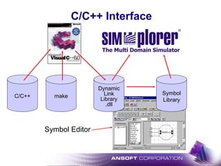
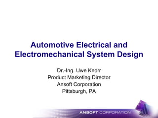
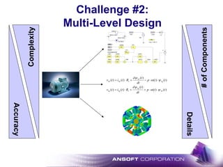
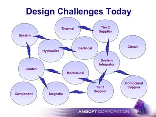
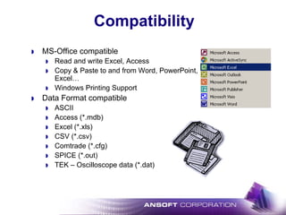
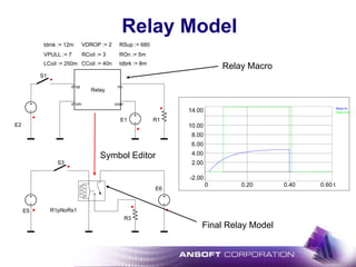
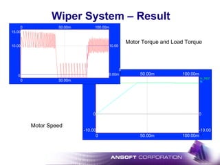
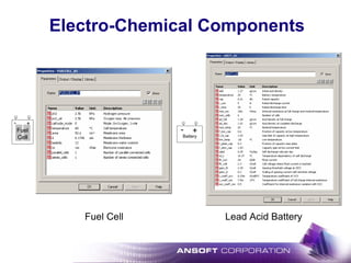
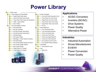
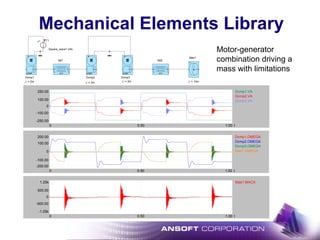
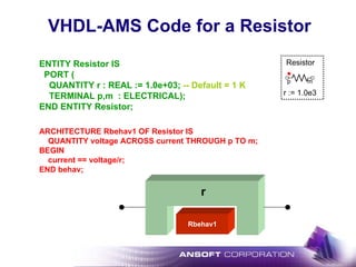
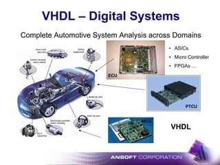
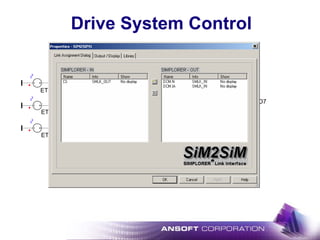
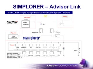
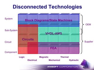
![DC Drive – C-Code Controller
L_R
0.3m
L_S
L_T
ET1
ET2
ET3
R_R
10m
R_S
R_T
DCM.IA [A]
t [s]
3.00e+001
0
2.00e+001
0
0
0.2
0.2
0.1
0.1
DCM.N [rpm]
N_REF.VAL
t [s]
1.50e+003
0
1.00e+003
0
0
0.2
0.2
0.1
0.1
motor
current
speed and
reference speed
LIMIT
LIMITER
LL := 0
UL := 20
GAIN
CONTR_OUT
THRES1 := -2.5
VAL1 := -1
THRES2 := 2.5
VAL2 := 1
CONST
N_REF
1000
M
DCM
J := 4m
LA := 9.5m
RA := 1.2
KE := 0.544
A
AM1
Bridge1.Vout [V]
Bridge1.Iout [A]
t [s]
1.00e+003
0
5.00e+002
0
0
0.2
0.2
0.1
0.1
DCM.MI [N·m]
TLoad.VAL
t [s]
2.00e+001
-1.00e+001
0
0
0
0.2
0.2
0.1
0.1
motor torque
and
load torque
DC Link
Voltage and
Current
D7
TR
TLoad
3
Bridge1
PIC
PIC1
IGain := 2
PGain := 3
C-Code](https://image.slidesharecdn.com/automotiveelectricalandelectromechanicalsystemdesign-130601172124-phpapp02/85/Automotive-electrical-and-electromechanical-system-design-48-320.jpg)
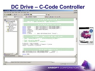
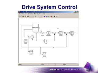
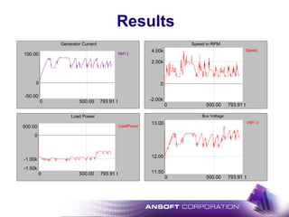
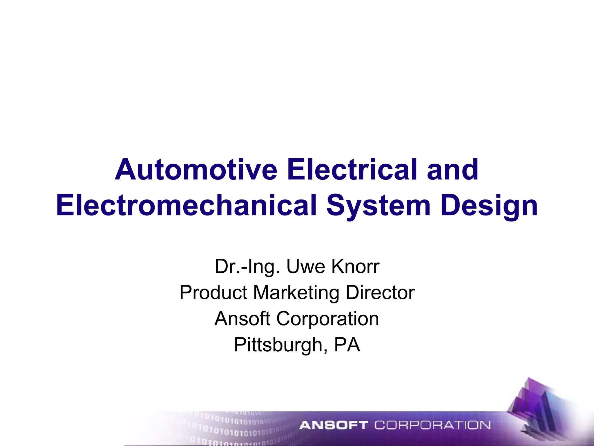
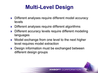
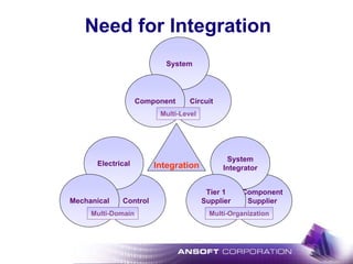
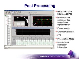
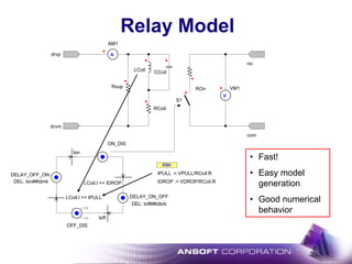
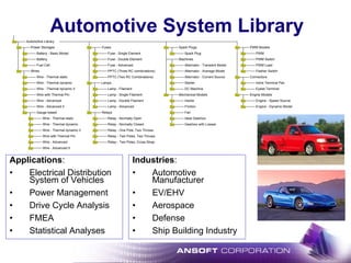
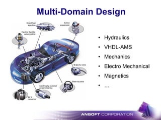
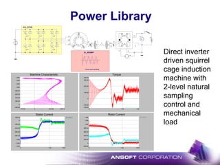
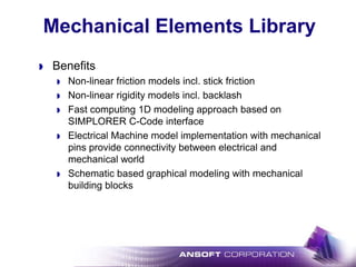
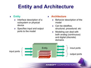
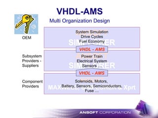
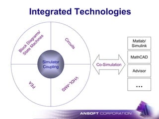
![E1 1
R1
500m
L1
R2 16
L2
C1 132.6u
31.83m
3.18m
OP: 0 V
OP: 0.969697 V
OP: 0.969697 V
OP: 1 V
Complete Set of Analyses
Bode
C1.VGain
Phase
100
100
1k
1k
200
200
300
300
400
400
500
500
600
600
700
700
800
800
900
900
100
100
1k
1k
200
200
300
300
400
400
500
500
600
600
700
700
800
800
900
900
-28.01
-20.00
0.00
20.00
-28.01
-20.00
0.00
20.00
0.00
0.79
1.57
2.36
3.14
0.00
0.79
1.57
2.36
3.14
f [Hz]
f [Hz]
[dB]
[rad]
AC Analysis](https://image.slidesharecdn.com/automotiveelectricalandelectromechanicalsystemdesign-130601172124-phpapp02/85/Automotive-electrical-and-electromechanical-system-design-59-320.jpg)


This document discusses the challenges of designing automotive electrical and electromechanical systems. It addresses multi-domain, multi-level, and multi-organizational design challenges. It promotes an integrated design environment to enable modeling of different domains, accuracy levels, and organizational interactions. Libraries of automotive-specific components are described to support electrical, hydraulic, and power system modeling.