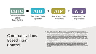
Automatic Train Control
Background
• A railway train is an ideal system for
automation. It uses a fixed guidance system,
its acceleration and braking can be
predicted, its position detected, its direction
confirmed and its timing regulated. However,
there are limitations:
• Train formations that can vary need to be
individually registered into the system;
• Not all existing railways are ideal for automation
and may need significant upgrades.
• Nevertheless, automation has considerable
benefits for safety and performance and can
offer better throughput of trains of up to 8% just
by the elimination of manual driving variability
Origins of
Automation
• The automation of train movements was to enforce
signal commands so that drivers could not allow
trains to pass beyond their limit of movement
authority (LMA).
• Originally, in Britain, the letters ATC referred to
"Automatic Train Control", which was the title given
to the warning system tried on some UK lines before
the general introduction of the AWS (Automatic
Warning System) in the 1960s. In the US it also
refers to Automatic Train Control but it refers to a
more modern concept where the system includes
ATP (Automatic Train Protection), ATO (Automatic
Train Operation) and ATS (Automatic Train
Supervision). ATC has been adopted around the
world to describe the architecture of the
automatically operated railway.
The ATC Package
• The first part of an ATC system is Automatic Train Protection (ATP), where the
train is given a Limit of Movement Authority (LMA). This is based on the
train’s current speed, its braking capability and the distance it can go before it
must stop.
• The second part of an ATC system is Automatic Train Operation (ATO). This is
the driving part of the operation. Looking at a manually driven train, we will
see that the driver initiates the starting of the train, allows its acceleration to
the permitted speed, slows it where necessary for speed restrictions and
stops at designated stations in the correct location. the ATO functions require
some form of on-board route map.
• The data received by the ATP control unit is usually limited to indicating that a
train is in the block or the speed limit currently imposed in the block. This
data is sent to the ATS computer where it is compared with the timetable to
determine if the train is running according to schedule or is late or early.
• The ATO spots, which can be short transmission loops or small boxes called
beacons or "balises", give the train its station stop commands.
• Some systems leave the ATO spots alone - i.e their data is always fixed - but
use the ATP system to prevent the train from starting or restrict its speed. The
ATS computer tells the ATP control unit to transmit a restricted speed or zero
speed to the track.
In the context of railways, "ATP" and "ATO" typically refer to specific systems related to train control and automation.
• ATP (Automatic Train Protection): ATP is a safety system designed to prevent accidents by automatically controlling the speed
and movement of trains. It monitors the train's speed and location and enforces speed restrictions and automatic braking if
necessary. The goal is to ensure that trains adhere to designated speed limits and maintain safe distances from other trains.
• ATO (Automatic Train Operation): ATO is a system that automates train operation functions, including acceleration, braking, and
stopping. ATO can work in conjunction with ATP to provide a higher level of automation. In some cases, ATO systems may also
include features like automatic door control, station stopping, and precise control of train movements.
These systems, when implemented together, enhance the safety and efficiency of railway operations. ATP focuses on safety by
preventing collisions and enforcing speed restrictions, while ATO contributes to operational efficiency by automating various aspects of
train control.
The Overlap
• If a line is equipped with a simple ATP system which automatically stops a
train if it passes a red signal, it will not prevent a collision with a train in
front if this train is standing immediately beyond the signal.
• There must be room for the train to brake to a stop. This is known as a "safe
braking distance" and space is provided beyond each signal to
accommodate it. In reality, the signal is placed in rear of the entrance to the
block and the distance between it and the block is called the "overlap".
Signal overlaps are calculated to allow for the safe braking distance of the
trains using this route.
Communications
Based Train
Control
• Much of the development effort in the area of new signalling systems is concentrated on
removing reliance on track-based equipment. Generically, this type of technology is referred
to as Communications Based Train Control (CBTC) and is broadly similar to ETCS Levels 2 or
even 3 in as much as conventional track circuits are not necessarily required for train
detection. Where trains do not report their own location using tachometers, Doppler radar
and balises, detection can be provided additionally by combinations of track circuits, or by
means of Global Positioning by Satellite (GPS) or Global Navigation Satellite Systems (GNSS)
as they are now called.
• Some CBTC systems use radio-based data bearers to transmit train locations to the central
control computers. These are now being used on some metros and people-mover systems
like the Las Vegas Monorail. However, some track-based data is still usually considered
essential in locations where track separation for parallel tracks and turnout (point) locking is
required.
ATP Code Transmission
• ATP signalling codes contained in the track circuits
are transmitted to the train. They are detected by
pick-up antennae (usually two) mounted on the
leading end of the train under the driving cab. This
data is passed to an on-board decoding and safety
processor. The permitted speed is checked against
the actual speed and, if the permitted speed is
exceeded, a brake application is initiated. In the
more modern systems, distance-to-go data will be
transmitted to the train as well. The data is also sent
to a display in the cab which allows the driver of a
manually driven train to respond and drive the train
within the permitted speed range.
• At the trackside, the signal aspects of the sections
ahead are monitored and passed to the code
generator for each block. The code generator sends
the appropriate codes to the track circuit. The code
is detected by the antennae on the train and passed
to the on-board computer. As we have seen, the
computer will check the actual speed of the train
with the speed required by the code and will cause a
brake application if the train speed is too high.
Beacon
Transmission
• The ATP data from the track to the train is
transmitted by using coded track circuits
passing through the running rails. It is
known as the "continuous" transmission
system. However, it does have its
limitations.
• There are transmission losses over
longer blocks and this reduces the
effective length of a track circuit to
about 350 metres.
• The equipment is also expensive
and vulnerable to bad weather,
electronic interference, damage,
vandalism and theft.
Data processing and the other ATP
functions are similar to the continuous
transmission system.
Operation With
Beacons
• the first balise (beacon) for the red signal gives the approaching Train 2
room to stop. Train 2 will get its stopping command here so that it stops
before it reaches the signal. The second beacon causes an emergency stop if
the train attempts to pass while the signal is still at danger.
• A disadvantage of the beacon system is that once a train has received a
message indicating a reduced speed or stop, it will retain that message until
it has passed another beacon or has stopped.
• In reality, it will not move even then, since it requires the driver to reset the
system to allow the train to be restarted. For this reason, this type of ATP is
normally used on manually driven systems.
Intermittent
Updates
• To avoid the situation of an unnecessary stop, an intermediate beacon
maybe provided as an infill loop. This updates the train as it approaches the
stopping point and will revoke the stop command if the signal has cleared.
More than one intermediate beacon can be provided if necessary
Moving Block- The
Theory
• As signalling technology has developed, there have been many refinements to the block system but, in recent years, the emphasis has
been on attempts to get rid of fixed blocks altogether. Getting rid of fixed blocks has the advantage that you can vary the distances
between trains according to their actual speed and according their speeds in relation to each other.
• As long as each train is travelling at the same speed as the one in front and they all have the same braking capabilities, they can, in
theory, run as close together as a few metres.
• Just allow some room for reaction time and small errors. What is worth doing, is making the the block locations and lengths
consistent with train location and speed, i.e. making them movable rather than fixed. This flexibility requires radio transmission,
sometimes called Communications Based Train Control (CBTC) or Transmission Based Signalling (TBS) rather than track circuit
transmission, to detect the location, speed and direction of trains and to tell trains their permitted operating speed.
• Thank you

Automatic Train Control for railway.pptx

  • 1.
  • 2.
    Background • A railwaytrain is an ideal system for automation. It uses a fixed guidance system, its acceleration and braking can be predicted, its position detected, its direction confirmed and its timing regulated. However, there are limitations: • Train formations that can vary need to be individually registered into the system; • Not all existing railways are ideal for automation and may need significant upgrades. • Nevertheless, automation has considerable benefits for safety and performance and can offer better throughput of trains of up to 8% just by the elimination of manual driving variability
  • 3.
    Origins of Automation • Theautomation of train movements was to enforce signal commands so that drivers could not allow trains to pass beyond their limit of movement authority (LMA). • Originally, in Britain, the letters ATC referred to "Automatic Train Control", which was the title given to the warning system tried on some UK lines before the general introduction of the AWS (Automatic Warning System) in the 1960s. In the US it also refers to Automatic Train Control but it refers to a more modern concept where the system includes ATP (Automatic Train Protection), ATO (Automatic Train Operation) and ATS (Automatic Train Supervision). ATC has been adopted around the world to describe the architecture of the automatically operated railway.
  • 4.
    The ATC Package •The first part of an ATC system is Automatic Train Protection (ATP), where the train is given a Limit of Movement Authority (LMA). This is based on the train’s current speed, its braking capability and the distance it can go before it must stop. • The second part of an ATC system is Automatic Train Operation (ATO). This is the driving part of the operation. Looking at a manually driven train, we will see that the driver initiates the starting of the train, allows its acceleration to the permitted speed, slows it where necessary for speed restrictions and stops at designated stations in the correct location. the ATO functions require some form of on-board route map. • The data received by the ATP control unit is usually limited to indicating that a train is in the block or the speed limit currently imposed in the block. This data is sent to the ATS computer where it is compared with the timetable to determine if the train is running according to schedule or is late or early. • The ATO spots, which can be short transmission loops or small boxes called beacons or "balises", give the train its station stop commands. • Some systems leave the ATO spots alone - i.e their data is always fixed - but use the ATP system to prevent the train from starting or restrict its speed. The ATS computer tells the ATP control unit to transmit a restricted speed or zero speed to the track.
  • 5.
    In the contextof railways, "ATP" and "ATO" typically refer to specific systems related to train control and automation. • ATP (Automatic Train Protection): ATP is a safety system designed to prevent accidents by automatically controlling the speed and movement of trains. It monitors the train's speed and location and enforces speed restrictions and automatic braking if necessary. The goal is to ensure that trains adhere to designated speed limits and maintain safe distances from other trains. • ATO (Automatic Train Operation): ATO is a system that automates train operation functions, including acceleration, braking, and stopping. ATO can work in conjunction with ATP to provide a higher level of automation. In some cases, ATO systems may also include features like automatic door control, station stopping, and precise control of train movements. These systems, when implemented together, enhance the safety and efficiency of railway operations. ATP focuses on safety by preventing collisions and enforcing speed restrictions, while ATO contributes to operational efficiency by automating various aspects of train control.
  • 6.
    The Overlap • Ifa line is equipped with a simple ATP system which automatically stops a train if it passes a red signal, it will not prevent a collision with a train in front if this train is standing immediately beyond the signal. • There must be room for the train to brake to a stop. This is known as a "safe braking distance" and space is provided beyond each signal to accommodate it. In reality, the signal is placed in rear of the entrance to the block and the distance between it and the block is called the "overlap". Signal overlaps are calculated to allow for the safe braking distance of the trains using this route.
  • 7.
    Communications Based Train Control • Muchof the development effort in the area of new signalling systems is concentrated on removing reliance on track-based equipment. Generically, this type of technology is referred to as Communications Based Train Control (CBTC) and is broadly similar to ETCS Levels 2 or even 3 in as much as conventional track circuits are not necessarily required for train detection. Where trains do not report their own location using tachometers, Doppler radar and balises, detection can be provided additionally by combinations of track circuits, or by means of Global Positioning by Satellite (GPS) or Global Navigation Satellite Systems (GNSS) as they are now called. • Some CBTC systems use radio-based data bearers to transmit train locations to the central control computers. These are now being used on some metros and people-mover systems like the Las Vegas Monorail. However, some track-based data is still usually considered essential in locations where track separation for parallel tracks and turnout (point) locking is required.
  • 8.
    ATP Code Transmission •ATP signalling codes contained in the track circuits are transmitted to the train. They are detected by pick-up antennae (usually two) mounted on the leading end of the train under the driving cab. This data is passed to an on-board decoding and safety processor. The permitted speed is checked against the actual speed and, if the permitted speed is exceeded, a brake application is initiated. In the more modern systems, distance-to-go data will be transmitted to the train as well. The data is also sent to a display in the cab which allows the driver of a manually driven train to respond and drive the train within the permitted speed range. • At the trackside, the signal aspects of the sections ahead are monitored and passed to the code generator for each block. The code generator sends the appropriate codes to the track circuit. The code is detected by the antennae on the train and passed to the on-board computer. As we have seen, the computer will check the actual speed of the train with the speed required by the code and will cause a brake application if the train speed is too high.
  • 9.
    Beacon Transmission • The ATPdata from the track to the train is transmitted by using coded track circuits passing through the running rails. It is known as the "continuous" transmission system. However, it does have its limitations. • There are transmission losses over longer blocks and this reduces the effective length of a track circuit to about 350 metres. • The equipment is also expensive and vulnerable to bad weather, electronic interference, damage, vandalism and theft. Data processing and the other ATP functions are similar to the continuous transmission system.
  • 10.
    Operation With Beacons • thefirst balise (beacon) for the red signal gives the approaching Train 2 room to stop. Train 2 will get its stopping command here so that it stops before it reaches the signal. The second beacon causes an emergency stop if the train attempts to pass while the signal is still at danger.
  • 11.
    • A disadvantageof the beacon system is that once a train has received a message indicating a reduced speed or stop, it will retain that message until it has passed another beacon or has stopped. • In reality, it will not move even then, since it requires the driver to reset the system to allow the train to be restarted. For this reason, this type of ATP is normally used on manually driven systems.
  • 12.
    Intermittent Updates • To avoidthe situation of an unnecessary stop, an intermediate beacon maybe provided as an infill loop. This updates the train as it approaches the stopping point and will revoke the stop command if the signal has cleared. More than one intermediate beacon can be provided if necessary
  • 13.
    Moving Block- The Theory •As signalling technology has developed, there have been many refinements to the block system but, in recent years, the emphasis has been on attempts to get rid of fixed blocks altogether. Getting rid of fixed blocks has the advantage that you can vary the distances between trains according to their actual speed and according their speeds in relation to each other. • As long as each train is travelling at the same speed as the one in front and they all have the same braking capabilities, they can, in theory, run as close together as a few metres. • Just allow some room for reaction time and small errors. What is worth doing, is making the the block locations and lengths consistent with train location and speed, i.e. making them movable rather than fixed. This flexibility requires radio transmission, sometimes called Communications Based Train Control (CBTC) or Transmission Based Signalling (TBS) rather than track circuit transmission, to detect the location, speed and direction of trains and to tell trains their permitted operating speed.
  • 14.

Editor's Notes

  • #3 As a definition, ATC refers to the whole system which includes all the other automatic functions and, for some of these functions at least, also includes a degree of manual intervention. ATC therefore, is the package which includes ATP, ATO and ATS
  • #4 . On a manually driven train, the driver manages this through a combination of route and stock knowledge and the visual information received from wayside signals. On the automated train, the data for the LMA is transmitted from the track to the train where the on-board computer registers the current speed and calculates the target speed that the train must reach and by when. This is electronically plotted in the form of a braking curve. If the train is allowed to exceed the profile of the curve, the brakes will automatically apply to bring the train to a stand (or at least to within the permitted speed).  Both ATP and ATO commands are picked up by receivers on the train and translated into motoring, braking or coasting commands.  Where a train can be manually driven, the ATP will still ensure the safety requirement but the ATO is overridden, the driver stopping the train in the stations by use of the cab controls. There are lots of variations of ATC around the world but all contain the basic principle that ATP provides safety and is the basis upon which the train is allowed to run.  ATO provides controls to replace the driver, while ATS checks the running times and adjusts train running accordingly The spots usually contain fixed data but some, usually the last one in a station stop sequence, transmit data about the time the train should stop (the dwell time) at the station and may tell it how fast to go to the next station (ATP permitting). 
  • #5 It's worth noting that the specific implementations and technologies used for ATP and ATO can vary between different railway systems and regions. These systems contribute to the overall goal of creating safer, more efficient, and automated railway transportation.
  • #6 Of course, lengths vary according to the s Overlaps are often provided on main line railways too. In the UK, it is the practice to provide a 200 yard (185 m) overlap beyond each main line signal in a colour light installation. Back in 1972 when it was decided upon, it was, after a review of many instances where trains had overrun stop signals, considered the maximum normally required. It was a rather crude risk analysis but it was the best they could afford. ite; gradient, maximum train speed and train brake capacity are all used in the calculation. In the US, the overlap is considered so important that a whole block is provided as the overlap. It is referred to as "absolute block". This means that there is always a vacant block between trains. It's rather wasteful of space and it reduces capacity but it saves the need to calculate and then build in overlaps for each signal, so it's cheaper. Like a lot of things in life, you get what you pay for. 
  • #9 To overcome some of these drawbacks, a solution using intermittent transmission of data has been introduced. It uses electronic beacons placed at intervals along the track. there are usually two beacons, a location beacon to tell the train where it is and a signalling beacon to give the status of the sections ahead. The beacons are sometimes referred to as "balises".
  • #11 This means that if the block ahead is cleared before Train 2 reaches its stopping point and the signal changes to green, the train will still have the stop message and will stop, even though it doesn't have to. Why, might you ask, can't the driver cancel the stop message like he does when the train has stopped and the signal changes to green? If he could cancel the stop message while the train was moving, the system would be no better than the AWS with its cancel button. ATP is "vital" or "fail-safe" and must not allow human intervention to reduce its effectiveness. 
  • #13 It’s rather like applying the freeway rules for speed separation - you don’t need to be a full speed braking distance from the car in front because he won’t stop dead. If you are moving at the same speed as he is, you could, in theory, travel immediately behind him and, when he brakes, you do. If you allow a few metres for reaction time to his brake lights and variations in braking performance, it works well. Although it only needs a few spectacular collisions on the freeways to disprove the theory for road traffic, in the more regulated world of the railway, although it could  not be applied without a full safe braking distance between trains, it has possibilities. trains could run as close together as 50 metres at 50 km/h. Well, that’s OK in theory but, in practice, it’s a different matter and, as yet, no one has taken moving block design this far and they are unlikely to do so in the near future. The recent ICE high speed accident in Germany where a train derailed, struck a bridge and stopped very quickly, effectively negates the safety value of the theoretical moving block system described above. This means that it is essential to maintain a safe braking distance between trains at all times.