
Recommended
Recommended
More Related Content
Similar to Minor_project.ppt.pdf
Similar to Minor_project.ppt.pdf (20)
Recently uploaded
Recently uploaded (20)
Minor_project.ppt.pdf
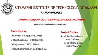
- 1. SITAMARHI INSTITUTE OF TECHNOLOGY, SITAMARHI MINOR PROJECT AUTOMATIC ROOM LIGHT CONTROLLER USING IR SENSOR Dept. of Electrical Engineering (2019-23) Project Guide:- Mr . Prabhakar kumar Ass. Professor. Dept. of Elec. Engg. S.I.T SITAMARHI Submitted by:- Surya sharma(18103127032) Raushankumar (18103127036) Raja raman (18103127044) Ravishankar kumar (18103127035)
- 2. Introduction Wastage of electricity is one of the main problems which we are facing nowadays. In our home, school, colleges or industry we see that fan/lights are kept on even if there is nobody in the room or area/passage. This happens due to negligence or because we forgot to turn lights off or when we are in a hurry. T o avoid all such situations we have designed this project called “Automatic room light controller using IR Sensor counter”. The main concept behind this project is known as “Visitor counter” which measures the number of persons entering any room like seminar hall, conference room, classroom. This function is implemented using a pair of Infrared sensors. LCD display placed outside the room displays this value of person count. Thisperson count will be incremented if somebody enters the room and at that time lights are turned on.And in a reverse way, person count willbe decremented ifsomebody leaves the room. When the number of persons inside the room is zero, lights inside the room are turned off using a relay interface. In this way Relay does the operation of “Automatic room light controller . The digital World we are living in allows us to use different technologies to automatically perform certain tasks. Such automation is very useful in certain areas like energy consumption, reducing human efforts,improving standard of living etc. The aim of this project is to automatically turn on or off the lights in a room by detecting the human movement. We implemented this project using 8051 microcontroller and two Infrared (IR) sensors.
- 3. USED HARDWARES Arduino UNO(1) Relay (5v)(1) R esisters (3), IR Sensor module(2) 16x2 LCD display(1) Bread Board(2) Connecting Wires (M toM-10, F to F-10,M to F-10) Led BC547 Transistor(5) Arduino Uno/MEGA Programming Cable(1) Arduino Uno R3ATmega328PArduino (1)
- 4. ARDUINO UNO Arduino is an open source physical processing which is base on a microcontroller board and an incorporated development environment for the board to be programmed. It takes in a few inputs, for instance,switches or sensors and monitors a few multiple outputs, for example, lights, engine and others. Arduino is a cross- platform app as its programs ca n run on Windows, Macintosh and Linuxoperating systems (OS) contrary to most microcontrollers' frameworks which run only on Windows. It is a very sophisticated physical processing stage focused around a straightforward microcontroller board. Fig. (01) ARDUINO UNO
- 5. Relay Relays are most commonly used switching devices used in electronics. It c a n be used to switch high current loads easily unlike transistors which are limited by the maximum current that c an flow through them and also can’t switchAC loads. This 5V 1A Relay Module can switch bothAC and DC loads. It is an Electromagnetic switch, when the coil inside is energized with a small current, it c an switch ON or OFF the high current circuit. It has PCB screw terminals to directly connect. They c an be used in Home automation to switch O N or OFF the appliances, in Electronic circuits to perform switching operations, in safety circuits to disconnect or connect the heavy loads in case of any dangerous situation, inAutomobile applications like turning on windscreen wipers, power windows fuel pump, cooling fan etc. Fig:- (02)
- 6. IR Sensor module Series are miniaturized receivers for infrared control systems. PIN diode and preamplifier are assembled on lead frame, the epoxy package designed IR filter .the demodulated output signal can directly be decoded by a microprocessor. TSOP17.. is the standard IR remote control receiver series, supporting all major transmission codes. Features: Photo detector and preamplifier in one package internal filter for PCM frequency -Improved shielding against electrical field disturbance -TTLa nd C M OS com p atibility -Output active low -Low power consumption -High immunity against ambient light -Continuous data transmission possible (up to 2400 bps) -Suitable burst length 10 cycles/burst fig. (03) IR Sensor module
- 7. Fig. (04) 16*2 LCD display LCD (Liquid Crystal Display) screen is an electronic applications. A 16x2 LCD disp la y is ve ry ba display module and find a wide range of sic module a nd is ve ry com monly used in various devices and circuits. These modules are preferred over seven segments and other multi segment LEDs. The reasons being: LCDs are economical: easily programmable; have no limitation of displaying special & even custom characters (unlike in seven segments), animations and so on. A 16x2 LCD mea ns it c a n disp la y 16 cha racters per line a nd there a re 2 such lines. In this LCD each character is displayed in 5x7 pixel m atrix.This LCD has two registers,nam ely , Co mma nd a nd Data. The command register stores the command instructions given to the LCD. A command is an instruction given to LCD to do a predefined task like initializing it, clearing its screen, setting the cursor position, controlling display etc. The data register stores the data to be displayed on the LCD. The data is the ASCII value of the character to be displayed on the LCD. 16x2 LCD display
- 8. Bread Board This is a modern "solderle ss" brea d b oard tha t is used to connect components without the use of solder . It simplifies the process of prototyping circuits. It is required for basic electronics. This breadboard has two power rails on both sides as well as 400 contact points. These contact points are holes on the breadboard into which wires and components can be inserted. Fig. (05) Bread Board
- 9. BC547 Transistor Basics of BC547 Here are the key points which you must know about BC547: BC 547 is a Bipola r Junction Transistor , a bbrevia ted a s BJT .Itis a n NPN transistor.Ithas three terminals named as: Emitter Collector BaseThe maximum current gain of BC547 is 800mA.Collector- Emitter Voltage is 65V.Collector-Base Voltage is 80n Emitter- Base Voltage is 8V.Working of BC547 BC547 has two working states which are: Forward Biased.Reverse Biased.In a forward biased state, the collector and emitter are connected allowing current to pass through. While in a reverse biased state, it works as an open switch and doesn't allow the current to pass. Applications of BC547 BC547 is normally used for: Current Amplification.Fast switching.Pulse Width Modulation. So if you have some project in which you wanna control the speed of a motor or actuator then you can easily do that by using this transistor. Moreover, it is also used as a switch i.e. if you want to turn on or off DC appliances then you can easily do that using this Fig.(06) BC547 T ransistor
- 10. Principle of operation This project is divided in four parts: sensors, controller , counter display and gate. The sensor would observe an interruption and provide an input to the controller which would run the counter increment or decrement depending on entering or exiting of the person. And counting is displayed on a 16x2 LCD through the controller. •When any one enters in the room, IR sensor will get interrupted by the object then other sensor will not work because we have a dde d a delay for a while.
- 13. Applications For counting purposes. For automatic room light control. It can be used at homes and other places to keep a check on the number of persons entering a secured place. Itcan also be used as home automation system to ensure energy saving by switching on the loads and fan on when needed.
- 14. Conclusion This is the controller based model to count the number of persons visitinga particular room/mall and accordingly light up the room. It counts the number of persons entering and leaving the room.