1.1 Launching AutoCAD
1.Choose Start from the Windows program manager.
2. Choose Programs, Autodesk ,AutoCAD 2009.
3. Click the AutoCAD 2009 for Windows icon.
4.
1.2 Text andGraphics Screens
The graphics screen and the text screen are two different screens available
in the drawing editor.
1. Press Function key F2 on the keyboard.
TIPS:
The Cursor must be in the drawing window in order to select objects.
Maximize the AutoCAD windows to be full screen. This will make the
drawings bigger and easier to read.
Use ALT + TAB to move between Windows applications.
5.
1.3 Cursor
Controls thesize of the crosshair. The allowable range is from 1 to 100
percent of the total screen. At 100% the ends of the crosshair are never
visible. When the size is decreased to 99% or below, the crosshairs
have a finite size, and the crosshairs’ ends are visible when moved to
the edge of the graphics area. The default size is 5%.
1. Choose Tools, Options…
2. Click the Display TAB.
3. Drag the slider bar in under crosshair size to set the cursor size.
6.
1.4 Canceling aCommand
1. Press the ESCAPE (ESC) key on the keyboard.
TIP: Pressing ESC twice clears nested commands.
7.
1.5 Menus andColors
Menu Browser
1. Click on the A icon in the upper left corner of the drawing area.
2. Click the desired pulldown menu.
3. Click on the command to be executed from the pulldown.
8.
Quick Access Toolbar
1.Click on one of the following icons for quick access to commands
QNEW, OPEN, SAVE, PLOT, and UNDO/REDO.
.
Right-click the Quick Access toolbar and click Customize Quick
Access Toolbar. The Customize User Interface dialog opens and
displays the list of commands available.
Drag commands you want to add from the command list pane in the
Customize User Interface dialog box to the Quick Access toolbar.
Info Center
Quickly search for a variety of information sources, access product updates
and announcements, and save topics with InfoCenter.
Ribbon
The ribbon provides a single, compact placement for operations that are relevant
to the current workspace. It eliminates the need to display multiple toolbars,
reducing clutter in the application window. The ribbon maximizes the area
available for work using a single compact interface.
The ribbon can be displayed horizontally, vertically, or as a floating palette. The
horizontal ribbon is displayed at the top of the drawing window by default when
you create or open a drawing.
You can create your own panels to display on the ribbon; you can also modify
the commands and controls on existing ribbon panels.
9.
1.6 Workspaces
You canswitch between the workspaces from the menu browser.
1. Click the Workspace switching icon in the lower left corner of the screen.
2. Click on one of the following workspace options
AutoCAD classic workspace
10.
1.7 AutoCAD ClassicToolbars
Toolbarscan be docked on the screen or they can float about the screen.
To Float a Toolbar:
1. Choose the gray border surrounding each tool.
2. Drag the toolbar to any area on the screen.
To Dock a Toolbar:
1. Choose the title or gray border of the toolbar.
2. Drag the toolbar to the top, bottom, left, or right area of the
graphics display.
Docked
Toolbars
Floating
Toolbars
TIP:
TIP:
-Holding the CTRL key while dragging will prevent docking.
-Holding the CTRL key while dragging will prevent docking.
11.
Loading Toolbars
Right-clicking onan icon in any toolbar
This will show a list of all available toolbars.
Help Tooltips
1. Move the mouse to the toolbar but do not pick the button.
12.
1.8 Status Barand Command Prompt
The Status Bar is the area below the command line that shows messages
as well as coordinates, modes, and the current time.
To activate SNAP, GRID, ORTHO, OSNAP, MSPACE, PSPACE, and TILE,
you must double-click on the mode to change.
Status Bar
TIP:
• Right click on the blank area of the status bar to see the tools to turn
off/on.
13.
1.9 Typing Commands
Typinga Command
All AutoCAD commands can be typed in at the command line. Many
commands also have one or two letter aliases that can also be typed as
shortcuts to the commands.
1. Type the desired command at the command prompt.
Command : LINE
or
2. Type the command’s alias.
Command: L
3. Press ENTER.
4. Type an option at the command prompt.
TIP:Many AutoCAD commands require you to press ENTER to complete
the command. You know you are no longer in an AutoCAD command when
you see a blank command line.
Reissuing the Last Command
The last used AutoCAD command can be re-entered by one of the following
three methods of ENTER. The ENTER key on the keyboard will always act
as ENTER, the SPACEBAR and RIGHT MOUSE will act as enter most of
the time (exceptions include placing TEXT).
1. Press the ENTER key on the keyboard
or
2. Press the Space bar on the keyboard.
or
3. Click the right mouse button.
14.
1.10 Pointing Device(Mouse)
AutoCAD uses either a mouse or digitizing tablet to select objects in a
drawing.
zing tablet to select objects in a
drawing.
Left Mouse Button
Left Mouse Button
Used to pick or select objects
Used to pick or select objects
1. Click the left mouse button to select an object area in the
drawing.
1. Click the left mouse button to select an object area in the
drawing.
2. Press ESC twice to deselect an object (or to cancel a
command).
2. Press ESC twice to deselect an object (or to cancel a
command).
Right Mouse Button
Right Mouse Button
Used to enter a command, repeat last command, or access shortcut menus.
Used to enter a command, repeat last command, or access shortcut menus.
1. Click the right mouse button.
1. Click the right mouse button.
LEFT
MOUSE
RIGHT
MOUSE
TIPS:
TIPS:
• SHIFT + the right mouse button brings up the object snap menus.
• SHIFT + the right mouse button brings up the object snap menus.
• Various screen locations for the mouse brings up different menus.
• Various screen locations for the mouse brings up different menus.
15.
1.11 Undo andRedo
Reverses the last action.
1. Choose Edit, Undo.
or
2. Click the Undo icon.
or
3. Press CTRL + Z.
4. Type U at the command prompt to undo the last command.
Command: U
Redo
Reverses the effects of a single UNDO or U command.
1. Choose Edit, Redo.
or
2. Click the Redo icon.
or
3. Type REDO at the command prompt to redo the last undo command.
Command: REDO
TIPS:
-UNDO has no effect on some commands and system variables, including
those that open, close, or save a window or a drawing, display information,
change the graphics display, regenerate the drawing, or export the drawing
in a different format.
-REDO must immediately follow the U or UNDO command.
1.13 On-Line Help
1.Choose Help, AutoCAD Help.
or
2. Click the Help icon.
or
3. Type HELP at the command prompt
Command: HELP
or
4. Press Function Key F1
2.1 Open ExistingDrawings
1. Choose File, OPEN.
or
2. Press CTRL + O.
or
3. Click the OPEN icon.
or
4. Type OPEN at the command prompt.
Command: OPEN
5. Press ENTER
6. Double Click the desired directory to find the drawing to
open.
7. Click the drawing name to open.
8. Click The OK button.
TIP:
-Preview shows a bitmap image of the drawing selected. This image is the
view that was last saved in the drawing. It will not show a preview of
drawings saved before R13 AutoCAD.
20.
2.2 Creating aNew Drawing
NEW Command
Creates a new drawing file.
1. Choose File, New.
or
2. Press CTRL + N
or
3. Click the New icon.
or
4. Type NEW at the Command prompt.
Command: NEW
5. Choose One of the options for creating a new drawing.
6. Click The OK button.
7. Save the drawing as another name.
TIP:
New drawings can also be created from Template Files.
21.
2.3 Saving Drawings
Savesthe most recent changes to a drawing. The first time an unnamed
drawing is saved the “Save As” dialog box appears. AutoCAD saves its
drawings as files with extensions ending in .DWG.
1. Choose File, Save or Saveas.
or
2. Type SAVE or SAVEAS at the command prompt.
Command: SAVE or SAVEAS
3. Press ENTER
4. Type A new drawing name or keep the existing drawing
name.
5. Click The OK button.
Various file types
the drawings
can be saved as
TIP:
Clicking the dropdown list for File type changes the format that the drawing
can be saved in.
22.
Quick Save
The QSAVEcommand is equivalent to clicking Save on the File menu.
If the drawing is named, AutoCAD saves the drawing using the file format
specified on the Open and Save tab of the Options dialog box and does not
request a file name. If the drawing is unnamed, AutoCAD displays the Save
Drawing As dialog box (see SAVEAS) and saves the drawing with the file
name and format you specify.
1. Press CTRL + S.
or
2. Click the Save icon.
or
3. Type QSAVE at the command prompt,
Command:QSAVE
TIPS:
Drawings can be saved as different versions of AutoCAD (e.g. R13, R14, R
2000, etc.)
AutoSave settings under Tools, Options…
23.
2.4 File SafetyPrecautions
Autosave
AutoCAD automatically saves information in .SV$ files; however, users
should save their drawings to .DWG files every 10 minutes. A value of zero
(0) disables autosave.
Temporary Files
These files have the extensions .ac$ (temporary drawing file).
After a system failure, if you are on a network, you should not delete
temporary files until you have verified that they are not part of an active
editing session.
Other temporary files may be left in the drawing directory or the temporary
file directory.
AutoSave and SV$ under Tools, Options...., Open and Save
TIP:AutoCAD creates .BAK files that can be renamed to .DWG files.
24.
Security Options
Specifies securitysettings to be used when your drawing is saved. The
Password option adds a password to a drawing when it is saved.
25.
2.5 Exiting AutoCAD
1.Choose File, Exit.
or
2. Type QUIT at the command prompt.
Command: QUIT
3. Press ENTER
4. Click Yes to save changes or No to discard changes.
3.1 Line Command
Createssingle straight line segments
1. Choose Draw, Line.
or
2. Click the Line icon.
or
3. Type LINE from the command prompt
Command: LINE or L
4. Press ENTER
5. Pick From point: (point)
6. Pick Specify next point or [Close/Undo]:(point)
7. Pick Specify next point or [Close/Undo]:(point)
8. Press ENTER to end line sequence
or
9. Type U to undo the last segment
To point: U (undo)
or
10. Type C to create a closed polygon
To point : C (close)
TIPS:
• You can continue the previous line or arc by responding to
the From point: prompt with a space or ENTER.
• Choose the right mouse button for the line pop-up menu to
appear while in the line command
28.
3.2 Cartesian CoordinateSystem
AutoCAD provides the user with an infinite two dimensional area to work
with. Any entities place on the working two dimensional plane can be
defined relative to the Cartesian coordinate system.
The Cartesian coordinate system divides a two dimensional plane with two
perpendicular axis. The X axis runs horizontal across the bottom of the
screen. The Y axis runs vertically along the left side of the screen. These
two axis intersect at the bottom left corner of the screen.
Each of these axis is further divided into segments. Each segment is given a
value. The X axis segments increase in value to the right. The positive X
values are to the right of the intersection of the two axis. The negative X
values are to the left. The positive Y values are above the intersection and
increase up. The negative Y values are below.
29.
Absolute Coordinates
1. Typex,y coordinate when AutoCAD asks for a point.
From point: 1,1
To point: 2,1
To point: 2,2
To point: 1,2
To point: 1,1
NOTE: If dynamic input (F12) is on, you must type the # sign before
entering absolute coordinates (e.g.#1,1).
Relative Coordinates
1. Type @deltax,deltay when AutoCAD asks for a point.
From point pick point
To point: @1,0
To point: @0,1
To point: @-1,0
To point: @0,-1
Polar Coordinates
1. Type @distance<angle when AutoCAD asks for a point.
From point: pick point
To point:@1<0
To point:@1<90
To point:@1<180
To point:@1<270
30.
3.3 Dynamic Input
DynamicInput provides a command interface near the cursor to help you keep
your focus in the drafting area.
When Dynamic Input is on, tooltips display information near the cursor that is
dynamically updated as the cursor moves. When a command is active, the tooltips
provide a place for user entry.
Turning Dynamic Input ON/OFF
1. Click Dyn on the status bar
or
2. Press F12
Tip: Right-click Dyn and click Settings to control what is displayed by each
component when Dynamic Input is on.
31.
3.4 Orthogonal Lines
Controlslines from being drawn at various angles to straight lines. When the
snap grid is rotated, ortho mode rotates accordingly.
1. Press Function Key F8.
or
2. Double Click ORTHO from the Status Bar.
or
or
3. Press CTRL + L.
3. Press CTRL + L.
Line drawn
with
ORTHO ON
Line drawn
with
ORTHO
OFF
32.
3.5 Polar Tracking
PolarSnaps work independently from snaps. With Polar Snaps on,
AutoCAD shows the distances and angles being displayed as the cursor
moves.
1. Choose Tools, Drafting Settings
or
2. Type DDSETTINGS at the command prompt.
Command : DDESTTINGS
3. Choose the Polar trackingTAB from the dialog box.
4. Select the desired incremental angle from the
dropdown list (or create a new angle).
5. Pick OK to exit the dialog box.
6. Draw a LINE using the Polar Snap references.
33.
3.6 Circles
Circle Command
1.Choose Draw, Circle.
or
2. Click the Circle icon.
or
3. Type CIRCLE at the command prompt.
Command: CIRCLE
4. Type One of the following options:
3P/2P/TTR/<<center point>>:
Circle, Center Radius
Circle, Center Diameter
Circle, Tangent, Tangent Radius
Circle, Tangent, Tangent, Tangent
or
5. Pick A center point.
6. Type A radius or diameter.
or
7. Pick A radius or diameter
Diameter/<<radius>>:
TIPS:
- To create circles that are the same size, press
ENTER when asked for the circle radius.
- When selecting a circle with a pickbox, be sure
to select the circumference of the circle.
34.
3.7 Arc Command
1.Choose Draw, Arc.
or
2. Click the Arc icon.
or
3. Type ARC at the command prompt
Command: ARC
4. Draw One of the arcs.
TIPS:
-Except for 3 point arcs, arcs are drawn in a COUNTERCLOCKWISE
direction.
- While in the arc command, press the right mouse button to select the
following options for arcs:
Arc Examples
3 point arc Start ,center, chord length
start, center, end Start, end, radius
Start , center, included angle Start, end, direction
4.1 Erase andSelection Sets
4.1 Erase and Selection Sets
Erasing Objects
Erasing Objects
1. Choose Modify, Erase.
1. Choose Modify, Erase.
or
or
2. Click the Erase icon.
2. Click the Erase icon.
or
or
3. Type ERASE at the command prompt.
3. Type ERASE at the command prompt.
Command : ERASE or E
Command : ERASE or E
4. Pick Object at the select object prompt.
4. Pick Object at the select object prompt.
Select objects: (pick object)
Select objects: (pick object)
5. Press ENTER when you are done choosing objects.
5. Press ENTER when you are done choosing objects.
Select objects: ENTER
Select objects: ENTER
Select
objects with
pickbox
TIP:
TIP:
• If the cursor is not touching an object, AutoCAD will create a crossing or
window selection as defined on the following pages.
• If the cursor is not touching an object, AutoCAD will create a crossing or
window selection as defined on the following pages.
37.
4.2 Selection SetOptions
Type one of the following options at the Select objects: prompt: (point)One
object.
ALL All objects within the drawing are selected
unless they are on frozen or locked layers.
Multiple Multiple objects selected without high
lighting (faster edits).
Last Last object.
Previous All objects in the previous selection-set.
Group Objects in a named group.
AUto Automatic BOX (if pick in empty area).
SIngle One selection (any type).
Add Add mode: adds following objects to selection-set.
Remove Remove mode: removes following objects
from selection-set.
Window and Crossing
Window
Objects fully enclosed within Window.
Crossing
Objects within or Crossing a window.
38.
WPolygon
All entities withinthe boundaries of a
polygon created by inputted points.
CPolygon
All entities within or touching the
boundaries of a polygon created by input.
Fence
Objects that are crossed by a temporary line.
Remove from Selection Set
1. Press SHIFT and select entities to remove them from the
selection set.
39.
4.3 OOPS
Reinserts thelast erased set of objects or block even if it was not the last
command issued. Otherwise Oops acts like UNDO.
1. Type OOPS at the command prompt to reinsert erased
objects
Command: OOPS
4.4 Selection Preview
SELECTIONPREVIEW
Controls the display of selection previewing
5.1 ZOOM
Increases ordecreases the apparent size of objects in the current viewport
1. Choose View, Zoom.
or
2. Click a Zoom icon.
or
3. Type ZOOM at the command prompt.
Command: Zoom or Z
4. Type One of the following zoom options:
The following are basic zoom options:
All Places entire drawing (all visible layers) on
display at once. Forces a regeneration.
Extents Displays current drawing content as large as possible.
Previous Restores previous view.
Window Designates rectangular area to be drawn as large as
possible.
Number Magnification relative to ZOOM All display
Number X Magnification relative to current display (1X)
Center Specifies center point and new display height.
Dynamic Permits you to pan a box representing the viewing
screen around the entire generated portion of the
drawing and enlarge or shrink it.
TIPS:
-While in the ZOOM command, click with the right mouse button to see the
menu to the right.
42.
5.2 PAN
Shifts thelocation of a view.
1. Choose View, Pan.
or
2. Click the Pan icon.
or
3. Type PAN from the command prompt.
Command: PAN or P
TIPS:
- While in the PAN command, click with the right mouse button to see the
following menu.
- Panning can also be done by using the window scroll bars
43.
5.3 Redraw andRegen
Redraw refreshes the current view.
1. Type Redraw at the command prompt
Command: Redraw or R
REGEN regenerates the entire drawing and recomputes the screen
coordinates for all objects. It also re-indexes the drawing database for
optimum display and object selection performance.
1. Type REGEN at the command prompt.
Command: REGEN or RE
TIP: When BLIPMODE is on, marker blips left by editing commands are
removed from the current viewport
Blips showing Blips removed after redraw
5.4 Blipmode
Controls the display of marker blips. When Blip mode is on, a temporary
mark in the shape of a plus sign (+) appears where points are specified.
BLIPMODE is off by default.
1. Type BLIPMODE at the command prompt.
Command: BLIPMODE
6.1 SNAP Command
1.Choose Tools, Drafting Settings...
or
2. Type SNAP at the command prompt.
Command: SNAP or SN
3. Type One of the following options: Snap
spacing or
[ON/OFF/Aspect/Style/Type]:
Turn Snap On/OFF
1. Press Function Key F9 to turn the snap
ON/OFF.
or
2. Double Click SNAP on the Status Bar.
or
3. Press CTRL + B.
TIP:
Click with the right mouse button on the SNAP
option from the status bar as a shortcut to changing
the snap settings.
46.
6.2 Grid Command
1.Choose Tools, Drafting Settings...
or
2. Type DSETTINGS at the command prompt.
Command : DSETTINGS (DS)
or
3. Type GRID at the command prompt.
Command: GRID
4. Type One of the following options:
Grid spacing(X) or ON/OFF/Snap/Aspect
<0000>:
Turn Grid On/Off
1. Press Function Key F7 to turn the grid ON/OFF.
or
2. Double Click GRID on the Status Bar.
or
3. Press CTRL + G.
47.
7.1 Running ObjectSnaps
An object snap mode specifies a snap point at an exact location on an
object. OSNAP specifies running object snap modes, which remain
active until you turn them off.
1. Choose Tools, Drafting Settings...
or
2. Type DDOSNAP at the command prompt
Command: DDOSNAP
or
3. Click OSNAP on the Status Bar.
4. Right Click the Object Snap TAB.
5. Choose an object snap to turn ON/OFF from the dialog
box.
48.
7.2 Case byCase (Temporary Mode)
1. Press SHIFT + the RIGHT MOUSE BUTTON.
or
2. Click one of the object snaps located Object Snap
toolbar icon.
or
3. Type The object snap at the prompt line.
Command: Line
From pt: ENDP
To pt: MID
To pt: CEN
TIP:
Case by Case objects snaps will override running mode object snaps
49.
7.3 Osnap Settings
Whenyou use any of the object snap settings, AutoSnap displays a marker
and a Snap tip when you move the cursor over a snap point.
1. Choose Tools, Options...
2. Select the Drafting tab in the Options dialog box.
3. Change settings and choose OK.
The following are object snap modes:
CENter Center of Arc or Circle
ENDpoint Closest endpoint of Line/Arc
INSertion Insertion point of Text/Block/Shape/
Attribute
INTersection Intersection of Lines/Arcs/Circles
MIDpoint Midpoint of a line/Arc or midpoint
NEAerst Nearest point on a Line/Arc/Circle/Point
APParent Int Finds where two entities would intersect
NODe Nearest point entity (or Dimension defini
tion point)
NONe None (off)
PERpendicular Perpendicular to a Line/Arc/Circle
QUAdrant Quadrant point on an Arc/Circle
QUIck Quick mode (first find, not closest)
TANgent Tangent to Arc or Circle
50.
7.4 Aperture
Controls thesize and appearance of the pickbox used for object snap
selection.
1. Type APERTURE at the command prompt
Command: APERTURE
2. Type The size of the target box ( 3-8 is a good size)
Size of target box in pixels (1-50): (number)
or
Aperture
AutoCAD 2D Tutorial
ListCommand 8.1
1. Choose Tools, Inquiry, List.
or
2. Click the List icon from the Inquiry Toolbar.
or
3. Type LIST at the command prompt.
Command: LIST or LI
4. Pick The object or objects to list.
Select objects: (select)
5. Press ENTER when you are finished choosing objects:
- 54 -
53.
AutoCAD 2D Tutorial
MeasuringDistances 8.2
1. Choose Tools, Inquiry, Distance.
or
2. Click the Distance icon from the Inquiry Toolbar.
or
3. Type DIST at the command prompt
Command: DIST
4. Pick The first point to measure from
First point: pick point
5. Pick The second point to measure to
Second point: pick point
Distance Between Circle Centers
TIP:
Be sure to use Object Snaps with the MEASURE command.
- 55 -
54.
AutoCAD 2D Tutorial
CalculatingAreas 8.3
1. Choose Tools, Inquiry, Area.
or
2. Click the Area icon.
or
3. Type AREA at the command prompt
Command: AREA
4. Pick The first point for area calculation
<First point>/Object/Add/Subtract: pick
5. Pick Next point: pick
6. Pick Next point: pick
7. Press ENTER when you are finished choosing points.
Area of Rectangle
Object Allows user to pick an object to calculate
area (circle or polyline).
Add Adds separate areas for a total area calculation
Subtract Subtracts areas from each other.
TIPS:
Be sure to use Object Snaps with the MEASURE command
To subtract an area, you must first be in “add” mode to add the first area.
- 56 -
55.
AutoCAD 2D Tutorial
IDCommand 8.4
1. Choose Edit, Inquiry, Locate Point.
or
2. Click the Locate Point Icon from the Inquiry Toolbar.
or
3. Type ID at the command prompt.
Command: ID
4. Pick A point to identity
Point : pick point
Using ID at the corner
of the box rests the
“0,0” origin for relative
coordinates
TIP:
AutoCAD returns the X,Y, and Z coordinates as well as making this the
last point entered in the drawing (to move relative from)
Be sure to use Object Snaps with the ID command.
- 57 -
56.
AutoCAD 2D Tutorial
UNITSCommand 8.5
1. Choose Format, Units...
or
2. Type DDUNITS at the command prompt.
Command: DDUNITS or UN
3. Choose a units and angle setting.
4. Choose a precision setting.
- 58 -
57.
AutoCAD 2D Tutorial
DrawingLimits 8.6
The drawing limits are two-dimensional points in the World Coordinate
System that represent a lower-left limit and an upper-right limit.
The drawing limits also govern the portion of the drawing covered by the
visible grid and determine the minimum area a ZOOM All displays.
1. Choose Format, Drawing Limits.
or
2. Type LIMITS at the command prompt
Command: LIMITS
3. Type One of the following options
On/Off/Lower left corner <.000,0.000>: 0,0
4. Type One of the following options for the
upper right limit:
Upper right corner <12.0000,9.0000>:36,24
Drawing with lower left limit of 0,0 and upper right limit of
36,24
TIPS:
You can also pick points to define the limits.
The limcheck variable controls whether or not you can draw outside the
limits that are set. A setting of 0 (off) indicates that you can draw outside
the limits and a setting of 1(on) indicates that you cannot.
- 59 -
58.
AutoCAD 2D Tutorial
PlotScales and Paper Sizes 8.7
The following is an example of setting up an AutoCAD drawing for a D
size sheet of paper (36 x24) with a scale of 1/16=1').
1. Size the object you’re drawing.
2. Border Size 36 x 24 plotted, 576' x 384' drawn.
For some plotters, deduct a 1/2 margin
on top, bottom, and left,and a 1 margin on
the right.
3. Limits Lower left limit 0,0.
Upper right limit 576', 384'.
4. Text Height for 1/8 notes, multiply by 192 which is
the reciprocal of the plot scale.
1/8 plotted, 24” drawn.
5. Hatch Scale for patterns other than architectural.
Hatch Scale = 192
6. Dimension Scale Dimscale = 192
7. Ltscale Ltscale = 96
Determine your object size
- 60 -
59.
AutoCAD 2D Tutorial
DecideBorder (Paper) Size
Decide the Scale Factor for Object which is at least 212’, 212’. To do this,
multiply the scale factor x paper size. (i.e.: 1/16”=1’-0’ has scale factor
192)
- 61 -
60.
AutoCAD 2D Tutorial
SetDrawing Limits
Determine Dim Scale, Hatch Scale, Ltscale, and Text Height
DIMSCALE
192 TEXT HEIGHT
HATCHSCALE
192
LTSCALE
96 (1/2 scale)
- 62 -
AutoCAD 2D Tutorial
PlotCommand 9.1
1. Choose File, Plot.
or
2. Click the Plotter icon.
or
3. Type PLOT at the command prompt.
Command: PLOT or PRINT
or
4. Press CTRL + P
- 64 -
63.
AutoCAD 2D Tutorial
PlotSettings
1. Choose the Plot Settings tab.
2. Choose the appropriate paper size based on the
chosen plotter.
3. Choose the paper units (inches or mm).
4. Choose the drawing orientation (Portrait, Landscape,
Upside down).
5. Choose the plotting area.
6. Choose the plot scale.
7. Choose plot to center or specify an x or y offset.
8. Click OK.
- 65 -
64.
AutoCAD 2D Tutorial
Addinga Plotter 9.2
Plotter Manager Wizard
1. Choose File, Plotter Manager
2. Double-Click the Add a Plotter Wizard icon.
AutoCAD adds a plotter configuration to a
saved plot file called ?.PC3. You can then load
from this file later.
3. Click Next >
4. Choose My Computer.
My Computer will configure a plotter using
Autodesk Drivers. System Printer will configure
AutoCAD using Window’s printer drivers that
are already installed.
5. Click Next >
- 66 -
65.
AutoCAD 2D Tutorial
Choosinga Plotter Driver
6. Choose one of the Autodesk Plotter options.
Your purchased plotter should be listed here.
If it is not, you can choose “Have Disk...” and
specify a location for a plotter driver.
You can also plot to a file by choosing the
DXB, Autodesk ePlot, or Raster File options.
Importing a .PCP or .PC2 file
7. Choose Import File...if you wish to import a previously
saved plot configurationfile.
8. Click Next >
- 67 -
66.
AutoCAD 2D Tutorial
Definea Port
9. Choose an available port.
NOTE: You can plot to a specific file name or
“Autospool” to a file which can be
automatically sent to the plotter at a later date.
10. Choose Next >
Saving a Plot Configuration Name
11. Type the file name you wish to save.
12. Choose Next >
13. Click Finish
AutoCAD will save
a new Plot configuration
icon.
- 68 -
67.
AutoCAD 2D Tutorial
PlotStyles 9.3
Add a Plot Style
A plot style controls how an object or layer is plotted by determining
plotted properties such as lineweight, color, and fill style. Plot style tables
collect groups of plot styles. The Plot Style Table Manager is a window
that shows all the plot style tables available in AutoCAD.
There are two plot style types: color-dependent and named. A drawing
can only use one type of plot style table. You can convert a plot style table
from one type to the other. You canalso change the type of plot style table
a drawing uses once it has been set.
1. Choose File, Plot Style Manager.
2. Double-Click Add a Plot Style Table Wizard icon.
3. Click Next >
4. Choose Start from Scratch to create a new Plot
Style.
You can also use a previously configured plot
style, import a style from a previous release of
AutoCAD, or import a pen table.
5. Click Next >
- 69 -
68.
AutoCAD 2D Tutorial
6.Choose Color-Dependent Plot Style Table
7. Click Next >
8. Type a name for the plot style table.
9. Click Next>
- 70 -
69.
AutoCAD 2D Tutorial
10.Choose “Plot Style Table Editor...”
11. Pick an AutoCAD color and assign properties to it.
For example, if you want all RED objects to
be plotted with a pen width of .25 mm, choose
that lineweight.
12. Choose Save and Close
13. Choose Finish
AutoCAD will save the file called COLORPLOTSTYLE.CBT
- 71 -
70.
AutoCAD 2D Tutorial
NamedPlot Styles 9.4
1. Choose File, Plot Style Manager.
2. Double-Click Add a Plot Style Table Wizard icon.
3. Click Next >
4. Choose Start from Scratch to create a new Plot Style.
5. Click Next >
6. Choose Named Plot Style Table
7. Click Next >
8. Type a name for the plot style table.
9. Click Next>
10. Choose “Plot Style Table Editor...”
11. Create names for various styles.
12. Choose Save and Close.
- 72 -
AutoCAD 2D Tutorial
MoveCommand 10.1
1. Choose Modify, Move.
or
2. Click the Move icon.
or
3. Type MOVE at the command prompt
Command: MOVE or M
4. Pick Objects to move
Select objects: (select)
5. Pick A point to move from
Base point or displacement: (pick point)
6. Pick A point to move to
Second point of displacement: (pick point)
Circle before move Circle after move
TIP:
To move an object a specified distance, type adistance at the second
point of displacement prompt: @1<0
- 74 -
73.
AutoCAD 2D Tutorial
CopyCommand 10.2
1. Choose Modify, Copy.
or
2. Click the Copy icon.
or
3. Type COPY at the command prompt.
Command: COPY or CP
4. Pick Objects to copy.
Select objects: (select)
5. Pick A point to move from.
Base point or displacement/Multiple: (pick point).
6. Pick A point to copy to.
Second point of displacement: (pick point)
or
7. Type A point to copy to.
Second point of displacement: @ 1<0
Duplicate objects copied Multiple objects copied
TIP:
• To copy many objects in the same copy command, type M for Multiple at
the “Base point or displacement/Multiple” option.
- 75 -
74.
AutoCAD 2D Tutorial
PreviousSelection 10.3
Places selected objects in the Previous selection set
1. Choose Modify, Move.
or
2. Click the Move icon.
or
3. Type MOVE at the command prompt.
Command: MOVE or M
4. Pick Objects to move.
Select objects: (P)
Previous Selection Set Highlighted
TIP:
AutoCAD requires that objects be selected in order to be processed. The
Select Objects prompt occurs after many commands, including the
SELECT command itself.
- 76 -
75.
AutoCAD 2D Tutorial
OffsetCommand 10.4
Offset Distance
To offset a specified distance:
1. Choose Modify, Offset.
or
2. Choose the Offset icon.
or
3. Type OFFSET at the command prompt.
Command: OFFSET or O
4. Type The distance to offset.
Offset distance or <Through point>: (number)
5. Pick The object to offset.
Select object to offset: (select object)
6. Pick A side to offset object to.
Side to offset: (pick side)
7. Pick Another object to offset
Select object to offset: (pick side)
or
8. Press Enter to end the command.
Offsetting objects by specifying a distance
- 77 -
76.
AutoCAD 2D Tutorial
OffsetThrough Point
To offset through point :
1. Type OFFSET at the command prompt
Command: OFFSET
2. Type T to specify a through point
Offset distance or <Through point>: (T)
3. Pick A point to offset through (HINT: use object
snaps) Select object to offset: (pick)
Through point: (select object)
Offset through a point
- 78 -
77.
AutoCAD 2D Tutorial
EXTEND10.5
1. Choose Modify, Extend.
or
2. Click the Extend icon.
or
3. Type EXTEND at the command prompt
Command: EXTEND
Select boundary edge(s)...
4. Pick The BOUNDARY edge to extend to
Select objects: (select)
5. Press ENTER to accept the boundary edge
Select objects: (press enter)
6. Pick The objects to extend
<Select object to extend> / Project /
Edge / Undo: Select an object, enter
an option, or press enter : (select)
7. Press ENTER when you are done choosing objects
Lines Extended
to an Arc
(Arc is boundary edge)
TIP:
- Use the object selection option FENCE to choose multiple objects
- 79 -
78.
AutoCAD 2D Tutorial
TRIM10.6
The TRIM command allows you to trim objects in a drawing so they end
precisely at a cutting edge defined by one or more other objects in the
drawing.
1. Choose Modify, Trim.
or
2. Click the Trim icon.
3. Type TRIM at the command prompt
Command: TRIM
Select cutting edge(s)...
4. Pick The CUTTING edge to extend to
Select objects: (select)
5. Press ENTER to accept the cutting edge
Select objects: (press enter)
6. Pick Objects to trim
<Select object to trim> / Project / Edge / Undo:
Select an object, enter an option, or press enter
7. Press ENTER when you are done choosing objects
Select object to trim/Undo: (press enter)
Lines Trimmed
to an Arc
(Arc is cutting
edge)
TIP: Hold the SHIFT key to interactively extend instead of trim.
- 80 -
79.
AutoCAD 2D Tutorial
Edgemode
Controlshow the TRIM and EXTEND commands determine cutting and
boundary edges.
0 Uses the selected edge without an extension.
1 Extends the selected edge to its natural boundary.
- 81 -
80.
AutoCAD 2D Tutorial
MIRROR10.7
1. Choose Modify, Mirror.
or
2. Click the Mirror icon.
or
3. Type MIRROR at the command prompt.
Command: MIRROR
4. Pick Objects to mirror.
Select objects:(select)
5. Pick First point of mirror line: (point)
6. Pick Second point: (point)
7. Type Yes to delete the original objects and
No to keep them.
Delete old objects? Y or N
Mirror Line
- 82 -
81.
AutoCAD 2D Tutorial
Mirrtext10.8
Mirror reflects (mirrors) text if 1, retains text direction if 0.
1. Type MIRRTEXT at the command prompt.
Command: MIRRTEXT
2. Type 1 to reflect the text and 0 to retain the text.
Current value <0> New value: 1 or 0
MIRRTEXT=ON
MIRRTEXT=OFF
- 83 -
82.
AutoCAD 2D Tutorial
ROTATE10.9
1. Choose Modify, Rotate.
or
2. Click the Modify icon.
or
3. Type ROTATE at the command prompt
Command : ROTATE
4. Pick Objects to rotate:
Select objects:(select)
5. Pick A pivot point to rotate around
Base point: (point)
6. Type A rotation angle<Rotation angle>/Reference:
(number)
or
7. Pick A rotation angle<Rotation angle>/Reference: (point)
- 84 -
83.
AutoCAD 2D Tutorial
ReferenceAngle Rotation
A positive angle causes counterclockwise rotation, and a negative angle
produces clockwise rotation. If you respond to the last prompt with r, you
can specify the current rotation and the new rotation you want. AutoCAD
prompts:
1. Type R for a rotation angle<Rotation angle>/Reference: (R)
2. Choose An existing rotation angle Rotation angle:
(number or points)
3. Choose A new rotation angle New angle:
(number or points)
TIP:
You can show AutoCAD the reference angle (by pointing to the two
endpoints of a line to be rotated), and then specify the new angle. You can
specify the new angle by pointing or by dragging the object.
- 85 -
84.
AutoCAD 2D Tutorial
SCALE10.10
1. Choose Modify, Scale.
or
2. Click the Scale icon.
or
3. Type SCALE at the command prompt
Command: SCALE
Select objects: (select objects)
4. Pick A pivot point to scale about Base point: (point)
5. Type A rotation angle<Scale factor>/Reference:(number)
or
6. Pick A scale factor<Scale factor>/Reference:
(point)
Scale factor/Reference: (points)
- 86 -
85.
AutoCAD 2D Tutorial
Scaleby Specifying Length
You can show AutoCAD the reference length (by pointing to the two
endpoints of a line to be scaled), and then specify the new length. You can
specify the new length by pointing, or by dragging the object.
1. Type R to define a reference length
Scale factor/Reference: (R)
2. Choose A reference scale factor
Reference length : (number or points)
3. Choose A new scale factor
New length: (number or points)
- 87 -
AutoCAD 2D Tutorial
TextCommand 11.1
Text
Creates a single-line text object
1. Type TEXT at the command prompt
Command: TEXT
or
2. Pick the Single Line Text icon from the Text Toolbar.
3. Pick A start point
Justify/Style/<Start Point>: (point)
or
4. Type J to change the justification or S to change the text
style.
5. Type A text height
Height <default>: (type value or pick two points)
6. Type A rotation angle
Rotation angle <default>: (angle or point)
7. Type A text string
Text: (type text string)
8. Press enter to exit the Text: prompt.
DTEXT (Dynamic Text)
Creates a single-line text object, showing the text dynamically on the
screen as it is entered.
1. Choose Draw, Text, Single Line Text.
or
2. Type DTEXT at the command prompt
Command : DTEXT
3. Follow the steps 3-8 from above.
- 89 -
88.
AutoCAD 2D Tutorial
TextJustification 11.2
1. Type JUSTIFYTEXT at the command prompt
Command: JUSTIFYTEXT
or
2. Pick the Justify Text icon from the Text Toolbar.
- 90 -
89.
AutoCAD 2D Tutorial
TextJustifications
A Aligns text between two designated endpoints (height and angle are not
requested in this case).
C Centers the text around a specified point.
F Aligns the text between two designated endpoints with a specified height
that varies only in its X scale factor.
M Centers the text both horizontally and vertically around a specified point.
R Right justifies the text at a designated endpoint.
S Selects a different text style.
TL Starts the top left portion of text at a given point.
TC Centers the top center of the text at a given point.
TR Ends the top of text at a given point.
ML Starts the middle left portion of the text at a given point.
MC Centers the middle of text at a given point.
MR Ends the text at the middle right portion at a given point.
BL Starts the bottom left portion of the text at a given point.
BC Centers the bottom center portion of the text at a given point.
BR Ends the bottom of text at a given point.
- 91 -
90.
AutoCAD 2D Tutorial
TextStyles 11.3
Style Command
1. Choose Format, Text Style...
or
2. Type STYLE at the command prompt.
Command: STYLE
3. Pick the Text Style icon from the Text Toolbar.
4. Choose a style from the menu or create a NEW style.
5. Choose a font file.
6. Type a height for the text (set to zero to vary heights)
7. Type a width factor for each character.
Width factor <1>: (enter)
8. Type an obliquing (slant) angle.
Obliquing angle <0>: (angle or enter)
9. Type Yes or No to place characters backwards.
Backwards? (Y or N)
10. Type Yes or No to draw characters upside down.
Upside down? (Y or N)
11. Type Yes or No to draw characters vertically
- 92 -
91.
AutoCAD 2D Tutorial
FontFiles
AutoCAD supports the following font types:
.SHX AutoCAD Fonts
.PFB Adobe Type I Fonts
.PFA
.TTF Windows True Type Fonts
TIP:
To replace the font globally in a drawing, type style at the command
prompt and keep the same style name but replace the font file with the
new font. When AutoCAD regenerates, it will replace all text drawn with
that style with the new font.
- 93 -
92.
AutoCAD 2D Tutorial
MultilineText 11.4
Mtext Command
1. Choose Draw, Text, Multiline Text...
or
2. Pick the Mtext icon.
or
3. Type MTEXT at the command prompt.
Command: MTEXT
4. Type One of the following options
Height/Justify/Rotation/Style/Width:
or
5. Pick 2Points to define the text window.
6. Type text or change an MTEXT setting.
- 94 -
93.
AutoCAD 2D Tutorial
MTEXToptions:
Rotation Controls the rotation angle of the text boundary.
Style Specifies the text style to use in paragraph text.
Height Specifies the height of uppercase text
Direction Specifies whether text is vertical or horizontal.
Width Specifies the width of the text boundary.
MTEXT Editor
- 95 -
94.
AutoCAD 2D Tutorial
EditingText 11.5
DDEDIT
1. Choose Modify, Text...
or
2. Click the Edit Text icon from the Text toolbar.
or
3. Type DDEDIT at the command prompt.
Command: DDEDIT or ED
4. Pick The text to edit.
Select objects: (pick text)
5. Pick Additional text or ENTER to end the
command.
Select objects: ENTER
Text Edit Dialog Box for TEXT and DTEXT Commands
Text Edit for MTEXT command
- 96 -
95.
AutoCAD 2D Tutorial
SpecialControl Codes 11.6
AutoCAD provides special control codes to return drafting symbols when
using text.
1. Type The following characters to return equivalent
symbol:
%%d degree symbol (°)
%%c diameter symbol (Ø)
%%p plus minus symbol (±)
%%u to start and stop underlining
(NOTE)
%%o to start and stop overscoring
(NOTE)
The MTEXT command has additional symbols that can be accessed by
right-clicking in the MText Editor for more Special Symbols.
- 97 -
96.
AutoCAD 2D Tutorial
SpellCheck 11.7
1. Choose Tools, Spelling
or
2. Type SPELL at the command prompt.
Command: SPELL
3. Pick The text to spell check.
Select objects: (pick text)
4. Choose Change or Ignore to modify or accept the spelling
of a word.
5. Pick Change Dictionaries to create your own dictionary.
- 98 -
97.
AutoCAD 2D Tutorial
AnnotativeText
Use annotative text for notes and labels in your drawing. You create annotative
text by using an annotative text style, which sets the height of the text on the
paper.
The current annotation scale automatically determines the display size of the text
in model space or paper space viewports.
For example, you want text to display at a height of 3/16" on the paper, so you can
define a text style to have a paper height of 3/16". When you add text to a viewport
that has a scale of 1/2"=1'0", the current annotation scale, which is set to the same
scale as the viewport’s, automatically scales the text to display appropriately at
4.5".
1. Create an Annotative text style using the STYLE command.
- 99 -
AutoCAD 2D Tutorial
Introductionto Layers and Layer Dialog Box12.1
1. Choose Format, Layer.
or
2. Type LAYER at the command prompt.
Command: LAYER (or LA)
or
3. Pick the layers icon from the Layer Control box
on the object properties toolbar.
AutoCAD 2005
Layer Properties
- 101 -
103.
AutoCAD 2D Tutorial
LayerOptions 12.2
? Lists layers, with states, colors and linetypes.
Make Creates a new layer and makes it current.
Set Sets current layer.
New Creates new layers .
ON Turns on specified layers.
OFF Turns off specified layers.
Color Assigns color to specified layers.
Ltype Assigns linetype to specified layers.
Freeze Completely ignores layers during regeneration.
Thaw Unfreezes specified layers Ltype.
Lock Makes a layer read only preventing entities from being
edited but available visual reference and osnap functions.
Unlock Places a layer in read write mode and available for edits.
Plot Turns a Layer On for Plotting
No Plot Turns a Layer Off for Plotting
LWeight Controls the line weight for each layer
TIP:
Layers can be set using the command line prompts for layers. To use this,
type –LAYER or -LA at the command prompt
1. Type Command: -LAYER or LA
2. Type One of the following layer options
?/Make/Set/New/ON/OFF/Color/Ltype/Freeze/Thaw:
- 102 -
104.
AutoCAD 2D Tutorial
LayerShortcuts 12.3
Changing the Layer of an Object
1. Click Once on the object to change.
2. Select the desired layer from the Layer Control Box
dropdown.
AutoCAD will move the object to the new
layer.
Select layer
Select object first
- 103 -
105.
AutoCAD 2D Tutorial
Makinga Layer Current
1. Click once on the Make Object’s Layer Current icon.
2. Select object whose layer will become current:
Match Properties
1. Choose Modify, Match Properties.
or
2. Click the Match Properties Icon from the Standard
toolbar.
or
3. Type Command : MATCHPROP or MA
4. Select the object whose properties you want to
copy (1).
5. Select the objects to which you want to apply the
properties (2).
- 104 -
106.
AutoCAD 2D Tutorial
LayerPrevious 12.4
1. Open an AutoCAD drawing with layers.
2. Turn layers on/off.
3. Zoom or perform any AutoCAD Command.
4. Type LAYERP at the command prompt.
Command: LAYERP
or
5. Click the Layer Previous icon.
- 105 -
107.
AutoCAD 2D Tutorial
LayerStates 12.5
1. Choose the layer icon.
2. Select various layers to be ON,OFF,FROZEN,LOCKED,
etc.
3. Choose the Save State button.
4. Choose Restore State to restore the layer settings.
- 106 -
108.
AutoCAD 2D Tutorial
ColorCommand 12.6
1. Choose Format, Color.
or
2. Type DDCOLOR at the command prompt.
Command: DDCOLOR or COL
or
3. Choose Color on the Object Properties toolbar and then
select a color from the list or select Other to display
the Select Color dialog box.
TIP:
These settings ignore the current layer settings for color.
By Layer
If you enter bylayer, new objects assume the color of the layer upon which
they are drawn.
By Block
If you enter byblock, AutoCAD draws new objects in the default color (white
or black, depending on your configuration) until they are grouped into a block.
When the block is inserted in the drawing, the objects in the block inherit the
current setting of the COLOR command.
- 107 -
109.
AutoCAD 2D Tutorial
Linetypes12.7
Loading and Changing Linetypes
1. Choose Format, Linetype...
or
2. Type DDLTYPE at the command prompt.
Command:DDLTYPE or LT
3. Choose Load... to see a list of available linetypes.
4. Choose the desired linetype to assign.
5. Click OK.
- 108 -
110.
AutoCAD 2D Tutorial
Lineweights12.8
Loading and Changing Lineweights
1. Choose Format, Lineweight...
or
2. Type LINEWEIGHT at the command prompt.
Command: LINEWEIGHT or LWEIGHT
or
4. Pick a lineweight to make current from the Object
Properties menu.
TIPS:
- Lineweights can also be assigned to layers.
- The Display Lineweights feature can be turned on/off on the status bar to
show or not show lineweights in the drawing, thus making regenerations
faster.
- Lineweights are displayed using a pixel width in proportion to the real-
world unit value at which they plot. If you are using a high-resolution
monitor, you can adjust the lineweight display scale to better display
different lineweight widths.
- 109 -
111.
AutoCAD 2D Tutorial
ObjectProperties 12.9
1. Choose Modify, Properties.
or
2. Click the Properties icon.
or
3. Type DDCHPROP or DDMODIFY at the command prompt.
Command: DDCHPROP (CH) or
DDMODIFY (MO)
4. Pick Objects whose properties you want to change
Pick a window for DDCHPROP, single object
for DDMODIFY.
Select objects:(select)
5. Press ENTER to accept objects.
Select objects: (press enter)
6. Choose One of the following properties to change.
- 110 -
AutoCAD 2D Tutorial
Break13.1
1. Choose Modify, Break.
or
2. Click the Breakicon.
or
3. Type BREAK at the command prompt. Command: BREAK
4. Pick Object tobreak.
Select object:(select oneobject)
5. Pick A second break point.
Enter second point: (point)
or
6. Type F to choose a different break point
Entersecond point (or F for first point):(F)
- 112 -
114.
AutoCAD 2D Tutorial
7.Pick The firstbreakpointonthe object
Enterfirstpoint: (point)
8. Pick A second break point
TIP:
Youcan also type coordinates instead of picking a
break point. Enter second point (or F for first point):
@3’<0
If you break a circle,it changes to an arc by deleting the portion
from the first point to the second, going counterclockwise.
Breaking a Polyline with nonzero width will cause the ends to
be cut square.
- 113 -
115.
AutoCAD 2D Tutorial
Stretch13.2
1. Choose Modify, Stretch.
or
2. Click the Stretchicon.
3. Type STRETCHatthe command prompt.
Command : STRETCH Select
objectsto stretchbywindow...
4. Type C to choose CROSSING window
Select objects: C
5. Pick A firstcorner tostretch. Firstcorner: (point)
6. Pick The opposite corner to windowthe objects to
stretch.
Othercorner:(point)
7. Press ENTERto acceptobjects to stretch.
8. Pick A base point to stretchfrom Base point:
(point)
- 114 -
116.
AutoCAD 2D Tutorial
9.Pick A point tostretch to Newpoint: (point)
or
10. Type Adistance tostretch. Newpoint: @1<0
TIP:
The Stretchcommand must usea CROSSING windowor aCROSSING
POLYGON window.
- 115 -
117.
AutoCAD 2D Tutorial
Fillet13.3
1. Choose Modify, Fillet.
or
2. Click the Filleticon.
or
3. Type FILLETat the command prompt. Command: FILLET
4. Pick Firstobject to fillet. Polyline/Radius/Trim<Selecttwo
objects>: selectfirstobject.
5. Pick Second objectto fillet.
Selectsecond object:select second object.
or
6. Type One ofthe following options:
P FilletsanentirePolyline.
R Sets the filletradius.
T Sets the trimmode(trimcuts the fillet
corner and no trimkeeps the fillet corner).
TIP:
• Youcanalso filletPARALLEL lines as well as PLINES with LINES
• Type a radius of zero (0) to create a clean90 degree corner.
- 116 -
118.
AutoCAD 2D Tutorial
Chamfer13.4
1. Choose Modify, Chamfer.
or
2. Click the Chamfer icon.
or
3. Type CHAMFERatthe command prompt.
Command: CHAMFER
4. Pick First objecttochamfer.
Polyline/Distance/Angle/Trim/Method<Selectfirst
line>:select firstobject
5. Pick Second object to chamfer.
Selectsecond object:select second object.
or
6. Type One ofthe following options:
P ChamfersentirePolyline.
D Setschamfer distances.
A Uses a distance and angle method instead of
twodistances.
T Sets the trimmode
M Sets the method todistance or angle.
Chamfer with equal distances Chamfer with different
distances
- 117 -
119.
AutoCAD 2D Tutorial
Array13.5
Rectangular Array
To draw rectangular array:
1. Choose Modify, Array.
or
2. Click theArrayicon.
or
3. Type ARRAYatthecommandprompt. Command : ARRAY
4. Pick Objectstoarray. Select
objects : (select)
5. Type Thenumberofrows topto bottom. Number ofrows(---)
<1>: (number)
6. Type The numberofcolumns left toright. Numberofcolumns
(|||)<1>:(number)
7. Type The unitcelldistancebetweenitemsineachrow.
Distance between rows:(+ number=up,-number
=down)
8. Type The unitcelldistancebetweenitems ineach column.
Distancebetweencolumns:(+number=right, - number
=left)
- 118 -
120.
AutoCAD 2D Tutorial
UnitCell
Distance
Between Rows
Unit Cell Distance
Between Columns
Polar Array
To draw a polar array:
1. Choose Modify, ARRAY.
or
2. Click the Arrayicon.
or
3. Type ARRAY atthecommandprompt. Command:ARRAY
4. Pick Objects toarray. Select
objects:(select)
5. Type P to drawa polararray. Rectangular orPolararray
(R/P): P
6. Pick Acenterpointfor the array. Center pointofarray: pick
point
7. Type The TOTAL number ofitemsinthe array. Number of
items: number
8. Type The number ofdegrees to rotate the objects. Degrees
tofill (+=CCW,-+CW)<360>:
number
- 119 -
121.
AutoCAD 2D Tutorial
9.Type Yesor No to rotate objects.
Rotate objectsas theyare copied?<y> Yor N
Center
point of
array
- 120 -
122.
AutoCAD 2D Tutorial
Lengthen13.6
1. Choose Modify, LENGTHEN.
o
r
2. Type LENGTHENatthe command
prompt. Command: _lengthen
Selectanobjector[DElta/Percent/Total/
Enterdelta lengthor [Angle]<0.0000>:2
Select anobject tochange or [Undo]: pickobject
Object before lengthen
Object after lengthen
- 121 -
AutoCAD 2D Tutorial
TransparentCommands 14.1
Transparent commands are those started while another is in progress.
Precede transparent commands with an apostrophe.
1. Type LINE at the command prompt.
Command: LINE
Specify first point: (pick point)
Specify next point or [Undo]: 'zoom
>>Specify corner of window, enter a scale factor
(nX or nXP), or
[All/Center/Dynamic/Extents/Previous/Scale/ Window]
<real time>: (pick corner)
>>>>Specify opposite corner: (pick other corner)
Resuming LINE command.
Specify next point or [Undo]: (pick point)
TIP:
Commands thatdo notselect objects, create newobjects,or
end the drawing sessionusuallycanbeusedtransparently.
- 123 -
125.
AutoCAD 2D Tutorial
MultipleCommand 14.2
Multiple repeats the specified command until canceled
If you want to repeat a command that you have just used,
press ENTER or SPACEBAR, or right-click your pointing
deviceat the Command prompt.
Youalsocanrepeatacommand byentering multiple,a space,and
the command name,asshowninthe following example:
1.Type MULTIPLEbeforeeachcommand
Command:multiple circle
- 124 -
126.
AutoCAD 2D Tutorial
Calculator(CAL Command) 14.3
Evaluates mathematicaland geometricexpressions
1. Type CAL atthe command
prompt. Command: cal
(or ‘cal) Initializing...>>
Expression:1+1
2
Numeric operators
( ) Groups expressions
^ Indicates exponentiation
* , / Multiplies, divides
+, - Adds, subtracts
Vector operators
( ) Groups expressions
& Determines the vector product of vectors (as a vector)
[a,b,c]&[x,y,z] = [ (b*z) - (c*y) , (c*x) - (a*z) , (a*y) - (b*x) ]
* Determines the scalar product of vectors (as a real number)
[a,b,c]*[x,y,z] = ax + by + cz
*, / Multiplies, divides a vector by a real number a*
[x,y,z] = [a*x,a*y,a*z]
+ , - Adds, subtracts vectors (points)
[a,b,c] + [x,y,z] = [a+x,b+y,c+z]
- 125 -
127.
AutoCAD 2D Tutorial
Convertsunits of measure
1. Type CAL atthe command prompt.
Command: cal(or ‘cal)
Initializing...>>Expression:cvunit(1,inch,cm)
2.54
Determines Angles
1. Type CAL atthe command prompt.
Command: cal(or ‘cal)
Initializing...>>Expression:ang(end,end,end)
45
- 126 -
AutoCAD 2D Tutorial
PlineCommand 15.1
A polyline is a connected sequence of line segments created as a single
object. You can create straight line segments, arc segments, or a
combination of the two.
1. Choose Draw,Polyline.
or
2. Pick the Pline icon.
3. Type PLINE atthe command prompt
Command : PLINE or PL
4. Pick Apoint onthe drawing tostartthe polyline
Frompoint:(select)
5. Type One ofthe following options
Arc/Close/Halfwidth/Length/Undo/Width/<endpointof
line>:
or
6. Pick Apoint to continue drawing
Arc/Close/Halfwidth/Length/Undo/Width/<endpointof
line>: (pickpoint)
Polyline as one segment
- 128 -
130.
AutoCAD 2D Tutorial
PLINEoptions:
ArcToggles to arc mode and you receive the follow
ing:Angle/CEnter/CLose/Direction/Halfwidth/
Line/ Radius /Second Pt/Undo/Width/<endpt of arc>:
Close Closes a polyline as it does in the line command.
Halfwidth Specifies the halfwidth of the next polyline seg ments.
Can be tapered.
Length Specifies the length to be added to the polyline in the
current direction.
Undo Undoes the previous pline segment as with the line
command.
Width Specifies the width of the next polyline segments. Can
be tapered.
Polyline with arcs Polyline with width .125
Tapered width polyline Tapered width arc polyline
- 129 -
131.
AutoCAD 2D Tutorial
EditingPolylines 15.2
1. Choose Modify, Polyline.
or
2. Pick the Pediticonfrom the ModifyII toolbar.
3. Type PEDIT at the command prompt
Command: PEDIT
4. Pick Pick a polyline to edit
SelectPolyline:(pick)
5. Type One ofthe following options:Close/Join/ Width/Edit
vertex/FitCurve/Spline/Curve/
Decurve/Undo/eXit
PEDIT options:
Close Closes open polyline segments
Join Connects polylines, lines, and arcs to existing polylines.
Width Changes the width for all polyline segments.
Fit curve Creates curved arc segments around pline vertices at the
direction you specify.
Spline Curve Creates a curve through control points on a polyline.
Decurve Straightens curved segments.
Edit Vertex Displays the following Edit Vertex Options:
Polyline widthchange SplinedPolyline
- 130 -
132.
AutoCAD 2D Tutorial
PLINEGEN
Setshow linetype patterns are generated around the vertices of a two-
dimensional polyline. Does not apply to polylines with tapered segments.
0 Polylines are generated to start and end with a dash at each
vertex
1 Generates the linetype ina continuous patternaround the
vertices of the polyline.
Edit Vertex Options
1. Type One ofthe following vertexoptions:
Next/Previous/Break/Insert/Move/Regen/Straighten/
Tangent/Width/eXit<N>:
Next Moves the X to the next vertex
Previous Moves the X to the previous vertex
Break Remembers the currently marked vertex and allows you
to move to another vertex. You can then remove the
segments between these vertices. Closed plines will
open.
Insert Adds a new vertex after the currently marked vertex.
Move Moves the locationofthe currently marked vertex.
Regen Regenerates the pline. Used with the widthoption.
Straighten Remembers the currently marked vertex and allows
youto move to another vertex. You can then replace
the segments between these vertices with a straight
one.
Tangent Attaches a tangent direction to the current vertex for later
use in curve fitting.
Width Changes starting and ending widths for the segment
following the marked vertex.
eXit Exits from editing vertices.
- 131 -
133.
AutoCAD 2D Tutorial
EditingMultiple Polylines 15.3
1. Type the PEDIT atthe command
prompt. Command: PEDIT
Selectpolyline or [Multiple]:M
Pickmultiple polylinesto edit.
- 132 -
134.
AutoCAD 2D Tutorial
ExplodeCommand 15.4
1. Choose Modify,Explode.
or
2. Pick theExplodeicon.
3. Type EXPLODE atthe command prompt.
Command: EXPLODE
or
4. Pick Theobjecttoexplode. Select objects: (pick)
Polyline before
explode
Polyline (line)
after explode
- 133 -
135.
AutoCAD 2D Tutorial
TurningLines into Polylines 15.5
Use the PEDIT command to pick lines. AutoCAD will ask if you want to turn
these lines into polylines. You can then use the JOIN option under PEDIT to join
additional lines to the polyline.
1. Command: pedit
Select polyline or [Multiple]: pick line
Object selected is not a polyline
Do you want to turn it into one? <Y>
Enter an option [Close/Join/Width/Edit
vertex/Fit/Spline/Decurve/Ltype gen/Undo]: j
TIP:
• Lines and Arcs must have a common endpoint to join them together.
- 134 -
AutoCAD 2D Tutorial
Polygon16.1
1. Choose Draw,Polygon.
or
2. Click the Polygonicon.
or
3. Type Polygonatthe command prompt.
Command:POLYGON
4. Type The number ofsidesfor the polygon
(3-1024)
Number ofsides<default>:number
5. Pick The centerofthe polygon. Edge/<Centerofpolygon>:
pick
or
6. Type E to define the polygonby two edges.
7. Type I or C to place the polygoninside or outside ofan
imaginarycircle. Inscribedincircle/Circumscribed
about circle (I/C):
Polygon Inscribed in an Polygon drawn with Edge
imaginary circle
Polygon circumscribed
around an imaginary circle
- 136 -
138.
AutoCAD 2D Tutorial
Rectangle16.2
1. Choose Draw, Rectangle.
or
2. Click the Rectangle icon.
or
3. Type Rectang at the command prompt Command:
RECTANG Chamfer/Elevation/Fillet/Thickness/Width/
<First corner>:
4. Pick first corner.
5. Pick other corner or type coordinates (i.e. @4,2).
- 137 -
139.
AutoCAD 2D Tutorial
Spline16.3
The SPLINE command creates a particular type of spline known as a
nonuniform rational B-spline (NURBS) curve. A NURBS curve produces a
smooth curve between control points
1. Choose Draw,Spline.
or
2. Click the Spline icon.
or
3. Type SPLINE at the command prompt
Command: SPLINE
4. Pick A start pointfor the spline
Object / <Enter firstpoint>:(pickpoint)
5. Pick Points untilyouaredone drawing splines
Enterpoint:(pickpoints)
6. Press Enter or close to complete the spline
7. Pick Starting tangentpointforthe spline
Enterstart tangent (pickpoint)
8. Pick Ending tangentpointforthe spline
Enterend tangent: (pickpoint)
- 138 -
140.
AutoCAD 2D Tutorial
Splineoptions:
ObjectConverts 2D or 3D spline-fit polylines to equivalent
Splines
Points Points that define the spline
Close Closes a spline.
Fit Tolerance Allows you to set a tolerance value that creates a
smooth spline.
TIP: Refer to AutoCAD online help topic for more information on spline options.
- 139 -
141.
AutoCAD 2D Tutorial
EditingSplines 16.4
1. Choose Modify,Object,Spline.
TIP: Drawings containing splines use less memory and disk space than those
containing spline-fit polylines of similar shape.
- 140 -
142.
AutoCAD 2D Tutorial
CovertPLINE to Spline 16.5
1. Draw a PLINE.
2. Type PEDIT to edit the polyline as a spline.
3. Choose Draw, Spline.
4. Type Object at the command prompt.
5. Click once on the polyline to turn it into a spline.
TIP: Use the LIST command to determine if an object is a PLINE or SPLINE.
- 141 -
143.
AutoCAD 2D Tutorial
Donut16.6
Donuts are filled rings or solid-filled circles that actually are closed
polylines with width.
1. Choose Draw,Donut.
or
2. Type Donutatthe command prompt.
Command: DONUT
3. Type A value for the insidediameter.
Insidediameter <last>: .5
4. Type A value for the outsidediameter.
Outsidediameter<last>: 1
5. Pick Apoint for the center ofthe donut.
Centerofdoughnut: (point)
- 142 -
144.
AutoCAD 2D Tutorial
Ellipse16.7
Creates an ellipse or an elliptical arc.
1. Choose Draw,Ellipse.
or
2. Choose the EllipseorPartialEllipseicon.
or
3. Type ELLIPSE atthe command prompt
Command: ELLIPSE
4. Type One ofthe following options: Arc/Center/Isocircle /<Axis
endpoint1>:
Ellipseoptions:
Axis endpoint 1 Defines the first axis by two specified endpoints. The
angle of the first axis determines the angle ofthe
ellipse. The first axis can define either the major or
the minor axis of the ellipse.
Axis endpoint 2: <Other axis distance> / Rotation: Specify a point or
enter a distance
Arc Creates an elliptical arc. The angle of the first axis
determines the angle of the elliptical arc. The first
axis can define either the major or the minor axis of
the elliptical arc.
Center Creates the ellipse by a specified center point.
Isocircle Creates an isometric circle in the current isometric
drawing plane.
Rotation The major axis is now treated as the diameter of a
circle that will be rotated a specified amount around
the axis. You enter an angle between 0 and 89.4
degrees.
- 143 -
AutoCAD 2D Tutorial
Multilines16.8
MLINECommand
Createsmultiple parallel lines.
1. Choose Draw, Multiline.
or
2. Type MLINE at the command prompt.
Command: MLINE
3. Pick A point to start the multiline.
Justification/Scale/STyle/<From point>: pick point
4. Pick A second point to continue the multiline.
<To point>: pick point
5. Pick The next point to continue drawing multilines.
Undo/<To point>: pick point
6. Press ENTER to end the mulitline
Close/Undo/<To point>: press enter or
7. Type C to close the multiline back to the first point.
Close/Undo/<To point>: c
- 145 -
AutoCAD 2D Tutorial
ConstructionLine 16.11
Creates aninfinite line.
1. Choose Draw,ConstructionLine
or
2. Choose the XLINE icon.
or
3. Type XLINE at the command prompt.
Command: XLINE
Specifyapointor[Hor/Ver/Ang/Bisect/Offset]:
XLINE Options
HOR Createsa horizontalxline passing throughaspecifiedpoint.
VER Createsa vertical xline passing throughaspecified point
ANG Createsan xline ata specifiedangle.
BISECT Createsanxline thatpasses throughthe selected angle vertex
and bisects the angle betweenthe first and second line
OFFSET Createsanxline paralleltoanotherobject.
- 149 -
151.
AutoCAD 2D Tutorial
RayCommand 16.12
Creates an infinite line in one direction.
1. Choose Draw, RAY
or
2. Type RAYatthe command
prompt.
Command:RAY
Specify a point :(pick through point)
- 150 -
AutoCAD 2D Tutorial
BHATCHCommand 17.1
1. Choose Draw,Hatch...
or
2. Click the Hatchicon.
or
3. Type BHATCHat the command prompt
Command: BHATCH
- 152 -
154.
AutoCAD 2D Tutorial
BHATCHoptions:
PatternType Sets the current pattern type by using
AutoCAD's predefined patterns or user defined
patterns.
Pattern Properties Sets the current pattern, scale, angle, and
spacing. Controls if hatch is double spaced or
exploded.
Pick Points Constructs a boundary from existing objects that
form an enclosed area.
Select Objects Selects specific objects for hatching. The
Boundary Hatch dialog box disappears and
AutoCAD prompts for object selection.
Inherit Properties Applies the properties of an existing
associative hatchto the current Pattern Type and
Pattern Properties options.
Preview Hatch Displays the hatching before applying it.
AutoCAD removes the dialog box and hatches
the selected areas.
Associative Controls associative hatching.
Apply Creates the crosshatching in the boundary.
- 153 -
155.
AutoCAD 2D Tutorial
AdvancedHatch Options 17.2
1. Choose the Advanced... TABfromthe BHATCH dialog.
2. Choose one ofthe following advancedoptions:
Define Boundary Set
Defines the set of objects AutoCAD analyzes when defining a boundary
from a specified pick point.
Hatchstyle
Specifies the method used to hatch objects within the outermost hatch
bound- ary. If there are no internal objects selected, specifying a hatching
style has no effect.
Boundary Options
Specifies whether or not the temporary boundary objects will be added to
the drawing.
- 154 -
156.
AutoCAD 2D Tutorial
GradientHatch 17.3
1. Choose the Gradient...TABfrom theBHATCH dialog.
2. Choose one ofthe following advancedoptions:
- 155 -
157.
AutoCAD 2D Tutorial
HATCHEDIT17.4
1. Choose Modify, Hatch...
or
2. Click the HatchEditiconfrom the Modify II toolbar.
or
3. Type HATCHEDITatthe command prompt.
Command : HATCHEDIT
4. Choose One ofthe BHATCHoptions to modify.
5. Pick TheOKbutton.
- 156 -
158.
AutoCAD 2D Tutorial
InheritHatch 17.5
1. Choose Draw,Hatch...
or
2. Click the Hatchicon.
or
3. Type BHATCHat the command prompt
Command: BHATCH
4. Choose InheritProperties.
5. Pick the crosshatchofanexisting associative hatchto make
thecurrentPatternTypeand Pattern Properties
options. Preview Hatch Displays the hatchingbefore
applying it.
- 157 -
AutoCAD 2D Tutorial
BoundaryCommand 18.1
Definestheobject type,boundaryset, and island detectionmethod for defining
boundariesfrompointsyouspecify.
1. Choose Draw,Boundary
or
2. Type BOUNDARYatthe command prompt.
Command: BOUNDARY
Boundary created
Pick
internal
point
- 159 -
161.
AutoCAD 2D Tutorial
RegionCommand 18.2
Regions are two-dimensional areas you create from closed shapes or
loops. Closed polylines, lines, and curves are valid selections. Curves
include circular arcs, circles, elliptical arcs, ellipses, and splines.
1. Choose Draw, Region
2. Type REGION atthe command prompt.
Command: REGION
Select objects: (pick boundary)
Selectobjects:1 found
1loopextracted.
1Regioncreated.
Object created as a region
- 160 -
162.
AutoCAD 2D Tutorial
MassProperties 18.3
Calculates the mass properties of regions orsolids.
1. Choose Tools,Inquiry, Region/MassProperties
2. Type MASSPROP atthe command prompt.
Command: MASSPROP
Select objects: (pick region)
---------------- REGIONS ----------------
Area: 11.1328
Perimeter: 16.3734
Bounding box: X: 3.1508 -- 7.1352
Y: 2.8950 -- 6.8942
Centroid: X: 5.1508
Y: 4.8946
Moments of inertia: X: 276.6983
Y: 305.3510
Product of inertia: XY: 280.6701
Radii of gyration: X: 4.9854
Y: 5.2372
Principal moments and X-Y directions about centroid:
I: 9.9891 along [1.0000 0.0000] J: 9.9891 along
[0.0000 1.0000]
Write analysis to a file? [Yes/No] <N>:
- 161 -
AutoCAD 2D Tutorial
CreatingLocal Blocks (BMAKE) 19.1
1. Choose Draw, Block, Make.
or
2. Click the MakeBlock icon.
or
3. Type BMAKE atthe command prompt.
Command: BMAKE or BLOCK
4. Type the name of the block.
5. Pick an insertion point.
6. Select objects to be included in the block definition.
7. Click OK.
Insertion point
Note You cannot use DIRECT, LIGHT, AVE_RENDER, RM_SDB, SH_SPOT,
and OVERHEAD as valid block names.
- 163 -
165.
AutoCAD 2D Tutorial
InsertingBlocks 19.2
1. Choose Insert, InsertBlock
or
2. Click the Inserticonfromthe INSERT toolbar.
3. Type INSERT atthe command prompt.
Command: INSERT
4. Choose the name to insert a localblockand Browse...to insert a
Wblock.
5. Choose the insertion point, scale, and rotation of the block.
Block Inserted with
Block Inserted with a ninety degree
rotation angle
a zero degree rotation angle
- 164 -
166.
AutoCAD 2D Tutorial
TypingInsert (-INSERT)
1. Type - INSERTatthe
command prompt.
Command: -INSERT
2. Type Block name toinsert.
Insert block name or (?) typename
3. Pick Aninsertion
point. Insertion
point:pickpoint
4. Press ENTER to keep the same xscale
factor as the originalblock. X
scale factor <1>Corner / XYZ:
5. Press ENTER to keep the same xscale
factor as the originalblock.
Yscale factor
(default=X):
6. Press ENTERto keep a rotation
angle of zero. Rotationangle
<0>:
or
7. Pick Arotationangle.
- 165 -
167.
AutoCAD 2D Tutorial
Controlthe Color and Linetype of Blocks 19.3
The objects in an inserted block can retain their original properties, can inherit
properties from the layer on which they are inserted, or can inherit the properties
set as current in the drawing.
You have three choices for how the color, linetype, and lineweight properties of
objects are treated when a block reference is inserted.
- Objects in the block do not inherit color, linetype, and lineweight
properties from the current settings. The properties of objects in
the block do not change regardless of the current settings.
- For this choice, it is recommended that you set the color,
linetype, and lineweight properties individually for each object in
the block definition: do not use BYBLOCK or BYLAYER color,
linetype, and lineweight settings when creating these objects.
- Objects in the block inherit color, linetype, and lineweight
properties from the color, linetype, and lineweight assigned to the
current layer only.
- For this choice, before you create objects to be included in the
block definition, set the current layer to 0, and set the current
color, linetype, and lineweight toBYLAYER.
- Objects inherit color, linetype, and lineweight properties from the
current color, linetype, and lineweight that you have set explicitly,
that is, that you have set to override the color, linetype, or
lineweight assigned to the current layer. If you have not explicitly
set them, then these properties are inherited from the color,
linetype, and lineweight assigned to the current layer.
- For this choice, before you create objects to be included in the
block definition, set the current color or linetype to BYBLOCK.
- 166 -
168.
AutoCAD 2D Tutorial
WblockCommand 19.4
Writes objects to a new drawing file.
1. Type WBLOCK at the command prompt
Command: WBLOCK
2. Type Adrawing name(and location).
3. Type A block name if a localblock already
exists. Block name: name
or
4. Press ENTER to create a block.
5. Pick Aninsertionpointonthe object
Insertionbasepoint: picka point
6. Pick Objects tocreate the block.
Select objects: pick objects
7. Press ENTERto end the selectionset.
- 167 -
169.
AutoCAD 2D Tutorial
Purge19.5
1. Choose File,Drawing Utilities,Purge.
or
2. Type PURGE atthe command prompt
Command: PURGE
3. Choose One ofthe following purgeoptions:
Purgeunused
Blocks/Dimstyles/LAyers/ LTypes/
SHapes/STyles/Mlinestyles/All:
- 168 -
170.
AutoCAD 2D Tutorial
DefiningAttributes 19.6
1. Choose Draw,Block,Define Attributes...
or
2. Type ATTDEFatthe command prompt. Command: ATTDEF
3. Choose TAGtospecifyeachattribute occurrencein thedrawing.
4. Choose Prompttofillinthe promptthatthe user sees when
placingthe attribute.
5. Choose Value tofillinadefaultvalue.
6. Pick Aninsertionpoint for eachattribute
7. Create Ablockwhichincludesthe newattributes.
Toggle the following modesettings toonor off.
Invisible Doesnotdisplay,butallows extraction.
Constant AlloccurrencesofthisAttribute have the samevalue.
Verify Issuesextrapromptsto verifyapropervalue.
Preset Doesnotpromptfor thisAttribute during Blockinsertion.
- 169 -
171.
AutoCAD 2D Tutorial
EditingAttributes 19.7
1. Choose Modify, Object, Attribute,Single...
or
2. Click the Edit Attribute iconfromthe ModifyII Toolbar.
or
3. Type ATTEDITatthe command prompt
Command: ATTEDIT
4. Pick The blockto edit
Selectblock: pick
- 170 -
172.
AutoCAD 2D Tutorial
BlockAttribute Manager 19.8
1. Open adrawing withattributes.
2. Type BATTMANatthe command prompt.
Command:BATTMAN
or
3. Choose Modify,Object,Attribute, Block Attribute
Manager
or
4. Click the BlockAttribute Managericonfrom the
Modify II Toolbar
- 171 -
173.
AutoCAD 2D Tutorial
SynchronizeAttributes 19.9
Updatesallinstancesofaspecifiedblockwiththe currentattributes defined for
theblock
1. Open adrawing withattributes.
2. Type ATTSYNC atthe command prompt.
Command:ATTSYNC
3. Click the BlockAttribute Managericonfrom the
ModifyIItoolbar.
4. Press Enteranoption[?/Name/Select] <Select>:
enter and selecta blockwithattributes.
5. Press ATTSYNCblockcomputer?[Yes/No]<Yes>:
entertosynchronies. ATTSYNCcomplete.
- 172 -
174.
AutoCAD 2D Tutorial
EnhancedAttribute Extract 19.10
The Editorenables youtoeditthe attributes inanindividualblock as opposed
to the Block Manager whichis used to Block Definitions.
1. Open a drawing with block attributes.
2. Choose Tools, Attribute Extraction...
or
3. Click the Attribute Extract icon from the Modify II toolbar.
4. Choose the Current Drawing radio button and Next.
5. Click Next to choose Xrefs and nested blocks from the
Settings window.
6. Click Next to not choose an existing template.
7. Choose the Blocks and Attributes to extract and Next.
- 173 -
175.
AutoCAD 2D Tutorial
8.Choose the View output.
9. Click Next.
10. Save the file phone.xls
11. Open the template in Excel.
- 174 -
AutoCAD 2D Tutorial
DesignCenter Overview 20.1
The AutoCADDesignCenter findsand tranfersblocks, text styles, layers,
dimensionstyles,etcfromdrawings, WEB
1. Choose Tools, AutoCADDesignCenter.
or
2. Press CTL+2 onthe keyboard.
or
3. Type ADCENTER at the command prompt.
Command: adcenter
- 176 -
178.
AutoCAD 2D Tutorial
DesignCenter Blocks 20.2
1. Choose Blocks from one ofthe Design Center
menus.
2. Drag and drop a block from the DesignCenter into a
drawing.
TIP:
• Blockswith attributeswillbe promptedas theyareinserted into the
drawing
- 177 -
179.
AutoCAD 2D Tutorial
Hatchingfrom the Design Center 20.3
1. Choose acrosshatchpatternfromthe following
AutoCAD directory
AutoCADxxxxSupportacad.pat or
AutoCADxxxxBackup
2. Drag and drop apatterninto a drawing.
TIP:
• Be sure the HPSCALE is setbefore dropping a hatch patterninto a
drawing.
- 178 -
180.
AutoCAD 2D Tutorial
20.4Tool Palettes
1. Choose Tool, ToolPalettes Window
2. Choose Palettesiconfrom the Standard Toolbar
- 179 -
AutoCAD 2D Tutorial
PointStyles 21.1
Changes the appearance ofpointsand point sizes.
1. Choose Format, PointStyle...
or
2. Type DDPTYPE atthe command prompt.
Command : DDPTYPE
- 181 -
183.
AutoCAD 2D Tutorial
PointCommand 21.2
1. Choose Draw,Point,Single or Multiple Point.
or
2. Click the Pointicon.
or
3. Type POINT atthe command prompt.
Command : POINT
4. Pick A point onthe drawing.
Point(point)
- 182 -
184.
AutoCAD 2D Tutorial
Divide21.3
1. Choose Draw,Point, Divide.
or
2. Type DIVIDEatthe command prompt
Command: DIVIDE
3. Pick Object to divide
Select object to divide:(pick one object)
You can select a single Line, Arc, Circle, or
polyline. If you enter a segment count between 2
and 32,767, Point entities will be placed along
the object to divide it into that number of equal
segments.
4. Type The number ofequalsegments to dividethe
objectinto<Numberofsegments>/Block:
(number)
Objects divided using points
- 183 -
185.
AutoCAD 2D Tutorial
or
5.Type B to specifya block instead ofa point to insert.
6. Type The name ofthe block to insert
Block name to insert:(name)
7. Type Yesor No to alignthe block with anobject
Alignblock with object? Yor N Numberof
segments:
8. Type The number ofequalsegments to dividethe
object into<Numberofsegments>/Block:
(number)
TIP: The Block must currently be defined within the drawing. If you answer yes to
the Align block? prompt, the Block will be rotated round its insertion point so
thatit isdrawntan- gent to the object being divided.
Objects divided using block symbols
- 184 -
186.
AutoCAD 2D Tutorial
Measure21.4
1. Choose Draw,Point,Measure.
or
2. Type MEASURE atthe command
prompt. Command: MEASURE
3. Pick Object to measure:Selectobject to measure:
(pick one object)
4. Type The length ofeachsegmentalong the object.
<Lengthofsegment>/Block:(number)
or
5. Type B to specifya block instead ofa point to insert.
Points placed along measured distance
(remaining length is on the right side of the line)
- 185 -
AutoCAD 2D Tutorial
GripsOverview 22.1
EntityGrips
Entity grips allow AutoCAD drawings to be edited in an entirely new way.
Without entering any edit commands, you can stretch, move, copy, rotate,
scale, and mirror entities. You can also snap to geometric features such as
endpoints,midpoints, centers,quadrants withoutentering objectsnaps.
Gripsare the small squares thatappear whenobjects are selected withthe
crosshairs directlyfrom thecommand prompt.
Unselected Grip
An unselected grip is one that has not yetbeenpicked withthe cursor,but is
anitem in the currentselectionset(itis highlighted).Pick anobject to see
grips.
- 187 -
189.
AutoCAD 2D Tutorial
SelectedGrip
A selected grip is the grip box that youselectwith the cursorto define the
base point to edit from. It has a solid filled color and is the grip location
thatediting is done from.
The red grip at the line endpoint is the selected grip
Cancelling Grips
1. Press ESC to clear GRIPS.
TIP: If gripsare visible onanobject, pressing the DELkeyor ERASEwill
delete the selectedobject.
- 188 -
190.
AutoCAD 2D Tutorial
HowTo Use Grips 22.2
1. Pick Theobjects youwant to edit.
2. Pick One of the grips to use as the base grip.
3. Press the SPACE BAR, or RIGHTMOUSE
BUTTONtocycle throughthe grip
modes.
or
4. Type Thekeyword for the mode you
want: Stretch(ST) Stretchthe
objects. Move(MO) Move the
objects. Rotate(RO) Rotate
theobjects. Scale (SC) Scale
the objects. Mirror(MI) Mirror
the objects.
5. Drag Themouse toperform the operation.
6. Type C to create a newcopyof the
selectionset enterC.
7. Type X to exit Grip mode.
- 189 -
191.
AutoCAD 2D Tutorial
CopyMultiple with Grips 22.3
If you use the COPYoptionwithanyone ofthe editcommands,a temporary
auxiliarysnapgridiscreated. Toinvoke the grid,hold the SHIFTkeyafter
specifying the locationofthe first copy. AutoCADthen uses the X and Yoffsets
from the originalentityto define the snap,grid,and rotationofthe remaining
entities.
Holding the SHIFT Key
while in Copy Mode will
create a copied array of
objects
- 190 -
192.
AutoCAD 2D Tutorial
GripsSettings (DDGRIPS Command) 22.4
1. Choose Tools,Options...
or
2. Type DDGRIPSat the command
prompt.
Command: DDGRIPS
3. Choose the Selectiontab from the dialog box.
4. Choose the Gripsetting tochange.
Enable Grips
Enables the display of grips. AutoCAD stores this setting in the GRIPS
system variable.
- 191 -
193.
AutoCAD 2D Tutorial
EnableGrips Within Blocks
Enables the display of grips on objects within blocks. If you disable this setting
(but have Enable Grips selected), blocks are assigned one grip at their insertion
point. Disable this setting to work on blocks with many objects. AutoCAD stores
this setting in the GRIPBLOCK system variable.
Unselected
Sets the color of unselected (unfilled) grips. Choosing this button displays the
Select C olor dialog box, in which you set the grip color. AutoCAD stores the
color in the GRIPCOLOR system variable.
Selected
Sets the color of selected (filled) grips. Choosing this button displays
the Select Color dialog,in which you set the grip color. AutoCAD stores
the color in the GRIPHOTsystem variable.
Grip Size
Changes the size of grips. To adjust the size of grips, move the slider box
left or right. AutoCAD stores the pixel size (1-255) of the grips in the
GRIPSIZE system variable. Changes the size of grips. To adjust the size
of grips, move the slider box left or right. AutoCAD stores the pixel size
(1-255) of the grips in the GRIPSIZE system variable.
- 192 -
AutoCAD 2D Tutorial
SelectionModes 23.1
1. Choose Tools,Options...
2. Choose the SelectionTAB from the following dialog.
3. Change the settingsas desired.
Noun/VerbSelection
Allows youto select anobject before starting a command. The command
affectsthe previouslyselectedobject or objects. Youcanalso set this option
by using the PICKFIRST system variable.
Use Shift to Add to Selection
Adds or removes an object to the selectionset when you pressSHIFTand
selectanobject.
Press and Drag
Draws a selectionwindowby selecting a point and dragging the pointing
device to a second point.
- 194 -
196.
AutoCAD 2D Tutorial
ImpliedWindowing
Initiates the drawing of a selection window whenyouselect a point outside
anobject.
ObjectGrouping
Selects all objects in a group whenyou select one object inthat group. With
GROUP youcancreate and name a setof objects for selection.
Associative Hatch
Determines which objects are selected when you select anassociative
hatch. If this optionis selected,boundaryobjects are also selected when you
select an associative hatch.
- 195 -
197.
AutoCAD 2D Tutorial
Groups23.2
1. Type GROUP atthe command prompt.
Command:GROUP
2. Type a name for a newgroup.
3. Choose the NewbuttonunderCreate Group.
4. Pick objects tobe includedinthe group.
5. Press ENTERwhendone choosing objects.
6. Pick OK.
Lines in a group
TurningGroupsON/OFF
At any time, toggle group selection
on and off by pressing either
CTRL+H or SHIFT+CTRL+A.
- 196 -
198.
AutoCAD 2D Tutorial
ObjectSelection Cycling 23.3
It is difficult to select objects that are close together or lie directly on
topofone another. The following example shows two lines and a circle
thatall lie within the selection pickbox
1. Press the CTRL keybeforechoosing objectsatthe
SelectObjectsprompt.
2. Pick repeatedly inthe areawheremultiple objectsare located.
AutoCAD will cycle throughallobjects that were touching
thepickbox.
3. Press ENTERwhenthe desiredobjecthighlights.
4. Press ENTERagain.
Objects touching pickbox First object selected highlights
Second object selected
- 197 -
AutoCAD 2D Tutorial
DrawOrder 23.5
1. Choose Tools,DisplayOrder.
or
2. Click the Draworder Iconfromthe Modify II Toolbar.
or
3. Type DRAWORDERatthe command prompt.
Command: DRAWORDER
Select objects: pick anobject.
- 199 -
201.
AutoCAD 2D Tutorial
ObjectFilters 23.6
1. Type FILTER at the Command prompt.
2. Select Line in the Object Selection Filters dialog box under
Select Filter.
3. Choose Add to List.
4. Choose Apply.
5. Type ALL at the Select Objects prompt or select a window.
Command:
FILTER Applying filter to selection.
Select objects: all
6 found
3 were filtered out.
- 200 -
202.
AutoCAD 2D Tutorial
QuickSelect 23.7
1. Type QSELECT at the command prompt.
Command: QSELECT
2. Enter the selection criteria (i.e.TEXTHEIGHT < .5)
3. Choose OK.
TIP: AutoCAD puts those object(s) into a selection set. Use the “P” previous
option to select these objects.
- 201 -
203.
AutoCAD 2D Tutorial
LayerFilters 23.8
1. Choose the layerdialogbox.
2. Choose the threedots (...) to invokethe filterdialog for layers.
3. Choose the type offilter youwould liketo use(e.g. layer name =
1st*)
- 202 -
204.
AutoCAD 2D Tutorial
PointFilters 23.9
AutoCAD point filters allow the user to specify one coordinate, such as the X,
with one pick and a second coordinate, such as the Y, with another pick. The
point filters are .X,.Y, .XY,.XZand .YZ. Only .X and .Yare used for two
dimensionaldrawings.
1. Type A command thatasks for a point.
Command:CIRCLE
2. Type .X whenAutoCAD asks for a point.
3P/2P/TTR/<centerpoint>:.X
3. Pick Thepoint tofilter(HINT: useosnaps)
of MID of pointon x axis
4. Pick The nextpointtofilter
(needYZ)
MID of point on y axis
5. Pick A diameter or radius
Diameter/<radius>: Pick or type a diameter
X point filter
Y point filter
Circle center is
placed at the
intersection
of the filters
- 203 -
AutoCAD 2D Tutorial
ExternalReference Files Overview
Attaches, overlays, lists, binds, detaches, reloads, unloads, renames, and
modifies paths to external references (xrefs) in the current (or host) drawing.
1. Choose Insert,ExternalReference...
or
2. Click the XrefIconfrom the Reference Toolbar.
or
3. Type XREF atthe command Prompt.
Command: XREF
The following are Xref characteristics:
-An external reference file is known as an “Xref”.
-Current drawing contains only a “pointer”, the path and filename, to the Xref.
-The current drawing does not increase much in size when it contains an Xref.
-The Xref is reloaded each time the current drawing is loaded, thus always
showing the latest revision of the Xref.
-Xrefs import their linetypes, layers, text styles, dimstyles, views, ucs’s,
vports, and blocks into their current drawing.
-Each Xref named object is prefixed with the xref drawing name and a pipe “|”
symbol.
(i.e. HOUSE|A-WALL for drawing house.dwg and layer a-wall)
- Xdep stands for external reference dependent objects.
- Xref’s layers can be turned on/off in the current drawing.
- Layer zero(0) resides on layer zero(0) of the current drawing.
- Xrefs can be bound to the current drawing,in which case they become blocks.
- 205 -
207.
AutoCAD 2D Tutorial
-Xreflayers cannot be made current the the drawing they are xreferenced into.
- Xrefs can be snapped to.
-Xref entities cannot be individually modified in the current drawing.
-Xrefs can be plotted.
-Xrefs can be detatched from the current drawing and will disappear.
-The current drawing pointer, file and pathname can be changed.
-Xrefs can be re-loaded during the current drawing session.
-Xrefs can be nested.
-Xrefs can be clipped to show parts of the reference files.
- 206 -
208.
AutoCAD 2D Tutorial
AttachingXrefs 24.1
Attaches, overlays, lists, binds, detaches, reloads, unloads, renames, and
modifies paths to external references (xrefs) inthe current (or host) drawing.
1. Choose Insert,ExternalReference
or
2. Type XATTACHatthe command prompt.
or
3. Click the XrefAttachIconfrom the Reference Toolbar.
4. Choose adrawing name toattach.
5. Specify the insertionparameters.
- 207 -
209.
AutoCAD 2D Tutorial
XrefLayers 24.2
Layer Dialog Box
-Each Xref named object is prefixed with the xref drawing name and a pipe
“|” symbol. (i.e. HOUSE|A-WALL for drawing house.dwg and layer a-wall)
-Xdep stands for external reference dependent objects.
-Xref’s layers can be turned on/off in the current drawing.
-Layer zero(0) resides on layer zero(0) of the current drawing.
-Xref layers cannot be made current the the drawing they are
xreferenced into.
- 208 -
210.
AutoCAD 2D Tutorial
Xclip24.3
Defines an xref or block clipping boundary and sets the front or back clipping
planes.
1. Choose Modify, Clip,XRef
or
2. Click the XclipIconfrom the Reference Toolbar.
or
3. Type XCLIP at the command prompt.
Command: XCLIP Selectobjects:
Othercorner:1 found Select objects:
pick referencefile
ON/OFF/Clipdepth/Delete/generatePolyline/
<New boundary>:
Specifyclipping boundary:
Selectpolyline/Polygonal/<Rectangular>: Firstcorner:
Other corner:pickcorners
Defining a Clipping Boundary
- 209 -
211.
AutoCAD 2D Tutorial
Xclipframe24.4
Controls visibility of xref clipping boundaries.
1. Choose Modify, Object,ExternalReference.
or
2. Type XCLIPFRAME atthe command prompt.
Command: XCLIPFRAME
0 Clipping boundary is not visible
1 Clipping boundary is visible
Turning xclip frame on/off
- 210 -
212.
AutoCAD 2D Tutorial
Bindingan Xref 24.5
Converts Xreference files to block definitions in the current drawing.
Associ- ated objects change names (i.e. the layer called HOUSE|A-
WALL becomes HOUSE$0$A-WALL). Binding looses the connection
to the referenced file. Xrefs can also be inserted like Wblocks.
To Bind an Xref:
1. Choose Insert,Xref Manager
2. Choose anxrefname.
3. Choose the Bind option.
4. Choose Bind or Insert.
5. Choose OK.
- 211 -
213.
AutoCAD 2D Tutorial
Xbind24.6
The XBIND command is used to bind layers, blocks, linetypes, styles, and
dimstyles of an attached xref without binding the entire xref.
1. Choose Modify,Object,External
Reference,Bind...
or
2. Click the Xbind Iconfromthe Reference Toolbar.
3. Type XBIND atthe command
prompt.
Command: XBIND
Block/ Dimstyle / LAyer/ LType /Style:
- 212 -
214.
AutoCAD 2D Tutorial
EditingXrefs (Xref Manager) 24.7
DetachingXrefs
Detaches one or more xrefs from your drawing, erasing all instances of
a specified xref and marking the xref definition for deletion from the
symbol table.
1. Choose a drawing name to detach from the Xref Dialog.
2. Choose the Detachoption.
Unload an Xref
Unloads one or more xrefs. Unloaded xrefs can be easily reloaded.
Unlike detach,unloading does not remove the xref permanently. It merely
sup- presses the display and regeneration of the xref definition, to help
current session editing and improvement of performance.
1. Choose adrawing name to unloadfrom the Xref Dialog.
2. Choose the Unloadoption.
- 213 -
215.
AutoCAD 2D Tutorial
Reloadan Xref
Marks one or more xrefs for reloading. This option re-reads and displays
the most recently saved version of the drawing.
1. Choose a drawing name to reload from the Xref dialog.
2. Choose the Reloadoption.
Opening Xrefs to Edit
1. Choose Modify, XrefandBlockEditing,OpenReference.
or
2. Choose Modify, Xrefand Block Editing, Edit XreferenceinPlace.
3. Edit the objects as desired.
4. Save the edits withthe following icons.
- 214 -
216.
AutoCAD 2D Tutorial
Overlayan Xref 24.8
Overlays are typically used when you need to view another drawing’s geometry
temporarily, but don’t plan to plot using that data. In the following illustration,
several people are working on drawings referenced by master.dwg. The
person working on a.dwg needs to see the work being completed by the
person working on b.dwg, but does not want to xref b.dwg because it would
then appear twice in master.dwg. Instead, the person overlays b.dwg, which
is not included when a.dwg is referenced by master.dwg.
1. Choose the Attachoptionfrom the XrefDialog.
or
2. Click the XrefAttachIconfrom the Reference Toolbar.
3. Choose adrawing name toattach.
4. Choose Overlayinthe AttachXrefdialogboxunder Reference
Type.
- 215 -
AutoCAD 2D Tutorial
LinearDimensions 26.1
1. Choose Dimension, Linear.
or
2. Click the Linear Dimension command from the toolbar.
or
3. Type DIM at the command prompt.
Command: DIM
Dim: HOR or VER
- 223 -
225.
AutoCAD 2D Tutorial
AlignedDimensions 26.2
1. Choose Dimension, Aligned.
or
2. Click the Aligned Dimensioncommand from the
toolbar.
or
3. Type DIM at the command prompt.
Command: DIM
Dim: ALIGNED
- 224 -
226.
AutoCAD 2D Tutorial
RadialDimensions 26.3
1. Choose Dimension, Radius or Diameter.
or
2. Click the Radial Dimensions command from the
toolbar.
or
3. Type DIM at the command prompt.
Command: DIM
Dim: RADIUS or DIAMETER
- 225 -
227.
AutoCAD 2D Tutorial
AngularDimensions 26.4
1. Choose Dimension, Angular.
or
2. Click the Angular Dimensions command from the
toolbar.
or
3. Type DIM at the command prompt.
Command: DIM
Dim: ANGULAR
- 225 -
228.
AutoCAD 2D Tutorial
Continuedand Baseline Dimensions 26.5
1. Choose Dimension, Continue or Baseline.
or
2. Click the Continue or Baseline Dimensions command
from the toolbar.
or
3. Type DIM at the command prompt.
Command: DIM
Dim: CONTINUE or BASELINE
- 226 -
229.
AutoCAD 2D Tutorial
Leaders26.6
1. Choose Dimension, Leader...
or
2. Click the Leader icon from the Dimension toolbar.
or
3. Type QLEADER at the command prompt.
Command: QLEADER
- 227 -
230.
AutoCAD 2D Tutorial
LeaderSettings
1. Type QLEADER at the command prompt.
Command: QLEADER
2. Type “S” at the QLEADER prompt to change the
leader settings.
3. Choose a setting from the following dialog box.
- 228 -
231.
AutoCAD 2D Tutorial
QuickDimensions 26.7
Quickly creates dimensionarrangements from the geometry you select.
1. Choose Dimension, QDIM.
or
2. Click the Quick Dimension icon from the Dimensions
toolbar.
or
3. Type QDIM at the command prompt.
Command: QDIM
4. Pick the objects to dimension.
- 229 -
232.
AutoCAD 2D Tutorial
ModifyingDimensions 26.8
DDEDIT
1. Choose Modify, Object, Text.
2. Choose the dimension text to modify.
TIP: The actual dimensionis placed in brackets <>. Text can be placed in
front of or behind these brackets. If text is placed between the brackets, the
dimensionloses its associative properties.
Stretching Dimensions
1. Choose Modify, Stretch.
2. Choose a crossing window around the area to stretch.
Be sure to include the dimension endpoints.
- 230 -
233.
AutoCAD 2D Tutorial
DIMTEDIT
Movesand rotates dimension text
1. Choose Dimension, AlignText. or
2. Type DIMTEDIT at the command prompt.
Command: DIMTEDIT
Select dimension: select object
Enter text location (Left / Right / Angle):
Dimension Edit Commands
HOMetext Moves the Dimension text back to its home (default)
position.
NEWtext Modifies the text of the Dimensions.
Rotate Rotates dimension text.
OBlique Sets the obliquing angle of Dimension extension lines.
OVerride Overrides a subset of the Dimension variable settings.
UPdate Redraws the Dimensions as directed by the current
settings of all dimensioning variables.
- 231 -
234.
AutoCAD 2D Tutorial
OrdinateDimensions 26.9
1. Choose Dimension, Ordinate
or
2. Type DIMORDINATE at the command prompt.
Command: Dimordinate
- 232 -
AutoCAD 2D Tutorial
CreatingDimension Styles 27.1
1. Choose Format, Dimension Style...
or
2. Choose Dimension, Style.
or
3. Choose Dimension Style icon from the Dimension Style toolbar.
4. Type DDIM at the command prompt
Command:DDIM
5. Choose New... from the dialog box.
6. Create a new style from the existing styles.
7. Click the Continue button.
TIP:
All dimension variables except for DIMSHO and DIMASO canbe saved as a
style.
- 234 -
237.
AutoCAD 2D Tutorial
Linesand Arrows 27.2
Edits Dimension Lines, Extension Lines, and Arrows.
1. Pick the Lines and Arrows tab from the Dimension Variables
and Styles dialog box.
- 235 -
238.
AutoCAD 2D Tutorial
Text27.3
Edits Text Appearance,Text Placement and Text Alignment.
1. Pick the Text tab from the Dimension Variables and Styles
dialog box.
- 236 -
239.
AutoCAD 2D Tutorial
PrimaryUnits 27.4
Edits Unit options for dimension’s primaryunits.
1. Pick the PRIMARY UNIT tab from the Dimension Variables
and Styles dialog box.
- 237 -
240.
AutoCAD 2D Tutorial
AlternateUnits 27.5
Edits Unit options for dimension’s alternate units.
1. Pick the ALTERNATE UNIT tab from the Dimension
Variables and Styles dialog box.
- 238 -
241.
AutoCAD 2D Tutorial
Tolerances27.6
Edits Unit options for tolerances.
1. Pick the TOLERANCES tab from the Dimension
Variables and Styles dialog box.
- 239 -
242.
AutoCAD 2D Tutorial
Fit27.7
Edits Unit options for fitting dimensions and dimension scales.
1. Pick the FIT tab from the Dimension Variables and Styles
dialog box.
- 240 -
243.
AutoCAD 2D Tutorial
Dimscale27.8
Edits Unit options for fitting dimensions and dimension scales.
1. Pick the FIT tab from the Dimension Variables and Styles
dialog box.
- 241 -
244.
AutoCAD 2D Tutorial
DimensionOverrride 27.9
1. Choose Dimension, Override.
2. Type a dimension setting to change (i.e. DIMSE1 which
suppresses the first extension line).
Command: _dimoverride
Enter dimension variable name to override or [Clear
overrides]: dimse1
3. Set the new value.
Enter new value for dimension variable <Off>: on
4. Press enter.
5. Pick the dimension to override.
- 242 -
245.
AutoCAD 2D Tutorial
DimensionVariables 27.10
1. Type SETVAR at the command prompt.
Command: SETVAR
Enter variable name or [?]: ?
Enter variable(s) to list <*>: dim*
DIMADEC 0
DIMALT OFF
DIMALTD 2
DIMALTF 25.4000
DIMALTRND 0.0000
DIMALTTD 2
DIMALTTZ 0
DIMALTU 2
DIMALTZ 0
DIMAPOST ""
DIMASO ON
DIMASSOC 1
DIMASZ 0.1800
DIMATFIT 3
DIMAUNIT 0
DIMAZIN 0
DIMBLK "ArchTick"
DIMBLK1 ""
DIMBLK2 ""
DIMCEN 0.0900
DIMCLRD 0
DIMCLRE 0
DIMCLRT 5
DIMDEC 1
DIMDLE 0.1250
DIMDLI 0.5000
- 243 -
246.
AutoCAD 2D Tutorial
DIMDSEP"."
DIMEXE 0.1800
DIMEXO 0.1250
DIMFIT 3
DIMFRAC 0
DIMGAP 0.0900
DIMJUST 0
DIMLDRBLK "Open90"
DIMLFAC 1.0000
DIMLIM OFF
DIMLUNIT 4
DIMLWD -2
DIMLWE -2
DIMPOST ""
DIMRND 0.0000
DIMSAH OFF
DIMSCALE 1.0000
DIMSD1 OFF
DIMSD2 OFF
DIMSE1 OFF
DIMSE2 OFF
DIMSHO ON
DIMSOXD OFF
DIMSTYLE "ARCH" (read only)
DIMTAD 1
DIMTDEC 1
DIMTFAC 1.0000
DIMTIH ON
DIMTIX OFF
DIMTM 0.0000
- 244 -
247.
AutoCAD 2D Tutorial
DIMTMOVE0
DIMTOFL OFF
DIMTOH ON
DIMTOL OFF
DIMTOLJ 1
DIMTP 0.0000
DIMTSZ 0.0000
DIMTVP 0.0000
DIMTXSTY "Standard"
DIMTXT 0.1800
DIMTZIN 0
DIMUNIT 4
DIMUPT OFF
DIMZIN 0
- 245 -
AutoCAD 2D Tutorial
NamedViews 28.1
Ddview Command
1. Choose View, Named Views...
or
2. Click the Named View icon from the View toolbar.
3. Type DDVIEW at the command prompt.
Command: DDVIEW
4. Choose the NEW button.
5. Type a view name.
6. Choose Current display or Define Window.
- 247 -
250.
AutoCAD 2D Tutorial
Typingthe View Command
1. Type View at the command prompt. Command: -VIEW
2. Type One of the following view options:
?/Delete/Restore/Save/Window:
View options:
? Lists the named views for this drawing
Delete Deletes the named view
Restore Displays the specified view
Save Attaches a name to the current viewof the drawing
Window Attaches a name to specified window
Plotting Named Views
- 248 -
251.
AutoCAD 2D Tutorial
Viewports28.2
Vports Command
1. Choose View, Viewports, New Viewports...
2. Choose one of the viewports configurations
3. Click OK.
4. Click once in each vport to make it active.
5. Type a ZOOM option in each viewport.
- 249 -
252.
AutoCAD 2D Tutorial
Viewportoptions
New Name Gives a name to a viewport
Restore Restores an original viewport
Delete DEL deletes a viewport
Join Joins two viewports together
SIngle Creates on viewport in the drawing
TIPS:
Viewports can be named and restored later.
AutoCAD plots only the current vport.
- 250 -
AutoCAD 2D Tutorial
Creatinga Layout 29.1
1. Choose the Layout1 TAB at the bottom of the screen.
2. Right-click Layout 1 to change the name and other properties
of a layout
- 252 -
255.
AutoCAD 2D Tutorial
CreatingMultiple Layouts 29.2
1. Choose the Layout2 TAB at the bottom of the screen.
2. Change the name of the layout.
3. Change the remaining Layout options for page setupand
plots.
- 253 -
256.
AutoCAD 2D Tutorial
QuickView Layouts 29.3
1. Choose Quick View Layouts from the status bar.
2. Choose a layout to view.
- 254 -
257.
AutoCAD 2D Tutorial
MviewCommand 29.4
• The MVIEW command controls the size and position of the mview
viewports (from now on called mviews). Mview is to tilemode = 0 as
vports is to tilemode = 1.
• Use mview when you would like to see a viewofthe model.
• Pspace mode must be active to use mview. AutoCAD will
automatically switch to pspace when you issue the mview command.
• The default mview option is "<<first point>>" To use this option, pick
a point which represents one corner of the mview. At the "other corner"
prompt, pick a point which represents the opposite corner of the
mview.
1. Choose View, Viewports, 1 Viewport.
or
2. Type Type MVIEW at the command prompt.
Command: MVIEW or MV
ON/OFF/Hideplot/Fit/2/3/4/Restore/<<First Point>>:
P1
Other corner: P2
TIP: Mviews should be created on their own layers in order to be turned
ON/OFF.
- 255 -
258.
AutoCAD 2D Tutorial
IrregularShaped Viewports 29.5
1. Draw a shape in Paper Space (e.g. circle, polygon, ellipse)
2. Choose View, Viewports, Object
3. Choose the object to make a viewport.
- 256 -
259.
AutoCAD 2D Tutorial
ModelSpace 29.6
MSPACE (modelspace) canonly be activated if there is atleast one mview.
To enter model space mode use "MSPACE".
1. Type MSPACE at the command prompt.
Command: MSPACEor MS
or
2. Double-Click the word “PAPER” on the Status Bar to toggle to
model space.
Notice the ucsiconwill appear ineachof the mviews whenyou enter model
space.
- 257 -
260.
AutoCAD 2D Tutorial
PaperSpace 29.6
PSPACE mode should be entered to create a border, a title, mviews, and
annotations only. This environment is used to lay out a 2 dimen- sional
working drawing suitable for plotting. When you plot from pspace, you should
plot 1=1.
1. Type PSPACE at the command prompt.
Command: PSPACE or PS
or
2. Double-Click the word “MODEL” on the Status Bar to toggle
to paper space.
Notice the "Paper" in the status line and the pspace icon.
- 258 -
261.
AutoCAD 2D Tutorial
Scales- Zooming in Model Space 29.7
• Use ZOOM "XP" to zoom the model a certain factor of the paper.
• If you enter a value followed by xp, AutoCAD specifies the scale
rela- tive to paper space units. For example, entering .5xp displays
model space at half the scale of paper space units.
• If you w ant to plot the m odel at 1/4”=1’, typeZOOM 1/48XP . If
you want to plot a part at 3 times, type ZOOM 3XP.
• Views can also be shown in 3D by using the VPOINT command.
1. Type MS at the command prompt to enter Model Space for
each individual viewport.
2. Type ZOOM at the command prompt. Command: ZOOM
All/Center/Dynamic/Extents/Previous/ Scale(X/XP)/
Window/<Realtime>: 3XP
You can also
change the scale
from the Viewports
Toolbar.
SCALE
2=1
ZOOM
1/4XP
SCALE
1=1
- 259 -
262.
AutoCAD 2D Tutorial
AddingText in Paper Space 29.8
Title block text and miscellaneous text can be added in Paper Space.
- 260 -
263.
AutoCAD 2D Tutorial
Plottingin Paper Space 29.9
• Plotting all MVIEWS should be done from Paper Space not from
ModelSpace.
• When you plot from pspace,you should plot1=1.
• For hidden line removals, remember to use the HIDEPLOT option in
the MVIEW command.
• Once a ZOOM SCALE has been defined, do not zoom again
before plotting. You can change the display with the PAN
command.
- 261 -
264.
AutoCAD 2D Tutorial
LayoutWizard 29.10
1. Choose Insert, Layout, Layout Wizard
2 Change the various options in the Layout Wizard.
- 262 -
AutoCAD 2D Tutorial
Tilemode29.11
Tilemode is anAutoCAD system variable which can be set to 0 or 1. When
tilemode is set to "1". viewportsact as they traditionally did, like floortiles.
Eachviewport butts up against the next. The viewports fill the screen. They
canonly be plotted one as a time. These traditional viewports are known as
"tiled areas of the screen". This is the default setting.
1. Type TILEMODE at the command prompt.
Command: TILEMODE
New value for tilemode <1> : Press ENTER
When tilemode is set to "0". The new metaview (mview) viewports can be
used. Mviews can be any size or place on the screen. They may overlap.
More than one mview canbe plotted at a time. Each mview can be quickly
turned onor off.
1. Type Command: TILEMODE
New value for tilemode <1> : 0
- 265 -
268.
AutoCAD 2D Tutorial
ViewportLayers 29.12
VPLAYER(viewport layer) controls layers on and off, and freeze and thaw, for
each mview. Layer controls the on and off, freeze and thaw, globally. Layers
must be on and thawed globally before they can be effected per mview with
vplayer.
1. Click in the viewport to change layer status.
2. Choose the layer dialog box.
3. Highlight the layer to freeze or thawin the current or new viewport.
The layer dialog boxalso allows control of layers for each viewport.
- 266 -
AutoCAD 2D Tutorial
AUDIT31.1
1. Choose File,Drawing Utilities, Audit.
or
2. Type Audit at the command prompt
Command: AUDIT
3. Type Yes or No to fix any errors
Fix any errors detected? <N>: Yor N
If a drawing contains errors thatAUDIT can't fix, use the RECOVERcommand
to retrieve the drawing and correct its errors.
- 277 -
280.
AutoCAD 2D Tutorial
RECOVER31.2
1. Choose File, Drawing Utilities, Recover....
or
2. Type RECOVER at the command prompt
Command : RECOVER
The RECOVER command performs recoveries or audit operations on DWG
files only. Performing a recover on a DXF file will only open the file.
- 278 -
281.
AutoCAD 2D Tutorial
PURGE31.3
1. Choose File, Drawing Utilities, Purge.
or
2. Type PURGE at the command prompt
Command: PURGE
3. Type One of the following purge options:
Purge unused Blocks/Dimstyles/LAyers/LTypes/
SHapes/STyles/Mlinestyles/All:
- 279 -
282.
AutoCAD 2D Tutorial
Rename31.4
1. Choose Format, Rename...
or
2. Type RENAME at the command prompt
Command: RENAME
3. Choose One of the following options to rename“ Block /
Dimstyle / LAyer / LType / Style / Ucs / VIew / VPort:
4. Type The old object name
Old (object) name: Enter the oldname
5. Type The new object name
New (object) name: Enter the new name
- 280 -
AutoCAD 2D Tutorial
ImportingFiles 32.1
1. Choose File, Open
or
2. Choose Insert, 3D Studio, ACIS, DXB, WMF, or ESP
or
3. Type Import at the command prompt.
Command: Import
- 282 -
AutoCAD 2D Tutorial
Copyingfrom AutoCAD 33.1
1. Launch a Windows program to link to (e.g. Microsoft Word)
2. Open an AutoCAD drawing.
3. Choose Edit, Copy.
4. Pick the AutoCAD objects to copy.
5. TAB to the Window’s program.
6. Choose Edit, Paste.
- 285 -
288.
AutoCAD 2D Tutorial
PrintScreen 33.2
1. Launch a Windows program to link to (e.g. Microsoft Word)
2. Open an AutoCAD drawing.
3. Press PRINTSCREENonthekeyboard.
4. TAB to the Window’s program.
5. Choose Edit, Paste.
- 286 -
289.
AutoCAD 2D Tutorial
OLELinking to AutoCAD 33.3
A linked object remains associated with its source file. When you edit a
linked object in AutoCAD, the source file changes. When you edit the
object in the source file, the linked object in AutoCAD changes.
1. Launch a Windows program to link from (e.g. Microsoft
Excel)
2. Create a spreadsheetto bring into AutoCAD.
3. Open an AutoCAD drawing.
4. Choose Insert, OLE Object.
5. Choose browse to pick a file to link to AutoCAD.
6. Pick a location in the drawing to place the OLE object.
- 287 -
290.
AutoCAD 2D Tutorial
7.Double Click to edit that object in the original program.
TIPS:
• Spreadsheets that are imported into AutoCAD drawings with OLE
are limited in size. If your spreadsheet is too large, you can reduce
the column width and row height, reduce the font size, or paste the
spreadsheet in separate parts to break the OLE object into smaller
OLE objects.
• OLE objects are inserted in an AutoCAD drawing on the current
layer. Turn off or freeze a layer to suppress the display of OLE
objects on that layer.
• Set the system variable OLEHIDE to display or suppress the
display of all OLE objects in paper space, model space, or both.
- 288 -
291.
AutoCAD 2D Tutorial
Hyperlinking33.4
1. Choose Insert, Hyperlink
or
2. Press CTRL + K
or
3. Type HYPE RLINK at the command prompt
Command: hyperlink
4. Select the object to hyperlink
Select objects: 1 found
5. Choose an option in the hyperlink dialog box.
- 289 -
292.
AutoCAD 2D Tutorial
Openinga Hyperlink 33.4
1. Move the cursor to the object with the hyperlink.
2. Click with your right mouse button.
3. Choose Hyperlink from the menu.
4. Open the file from the menu.
- 290 -
AutoCAD 2D Tutorial
34.1Plotting to the WEB
1. Type PLOT at the command prompt.
Command: plot
2. Choose the Plot Device TAB.
3. Choose the dropdown list for Plotter Configuration.
4. Plot to a .DWF, JPG, or PNG file.
• DWF format does not compress the drawing file.
• JPEG format uses lossy compression; that is, some data is
deliberately discarded to greatly reduce the size of the compressed
file.
• PNG (Portable Network Graphics) format uses lossless
compression; thatis, no original data is sacrificed to reduce the
size of the file.
- 292 -
295.
AutoCAD 2D Tutorial
34.2Configuring DWF Files
1. Type PLOT at the command prompt.
Command: plot
2. Choose the DWF plot configuration option.
3. Choose the Properties...button.
4. Choose Custom Properties….
5. Slide the slider bar to extreme for a clearer resolution on the
DWF file.
- 293 -
296.
AutoCAD 2D Tutorial
34.3Publish Command
1. Choose the Publishto WEB icon from the Standard Toolbar.
or
2. Choose File, Publish
3. Type PUBLISH at the command prompt.
Command: publish
- 294 -
297.
AutoCAD 2D Tutorial
34.4Publishing WEB Pages
1. Choose File, Publish to WEB.
or
2. Type PUBLISHTOWEB at the command prompt.
Command: PUBLISHTOWEB
3. Click Create New Web Page and Next.
4. Specify a name for the WEB page, location and description
for the new WEB page and click Next.
(NOTE: Save the WEB pages to C:TEMP)
- 295 -
298.
AutoCAD 2D Tutorial
4.Select PNG as the image type for the drawings and Image
Size “Medium” and click Next.
NOTE: If you have the Express Viewer loaded, you
can pick DWF files to view. This will allow you to
zoom and pan the drawings.
5. Select Array of ThumbNails as theTemplate type and click
Next.
- 296 -
299.
AutoCAD 2D Tutorial
6.Select a Theme (color) and click Next.
7. Select Enable i-drop and Click Next
- 297 -
300.
AutoCAD 2D Tutorial
8.Select drawings and/or layouts to place on the WEB page.
9. Click Regenerate all images and Next.
- 298 -
AutoCAD 2D Tutorial
34.4e-Transmit
1. Type ETRANSIT at the command prompt.
Command:etransmit
e-Transmit options
.EXE (files are self extracting)
.ZIP (PKZIP or WINZIP is needed to extract files)
- 300 -
303.
AutoCAD 2D Tutorial
34.6i-Drop
i-drop allows users to drag a drawing from an i-drop handle on an i-drop
supported WEB site to an open AutoCAD drawing. Choose the i-drop
option when publishing to the WEB to create an i-drop enabled WEB page.
1. Type http://www.autodesk.com/idrop to learn more about
Autodesk’s i-drop technology.
- 301 -
AutoCAD 2D Tutorial
AutoCADDWF Viewer 35.1
1. Launch Your WEB Browser.
2. Type http://www.autodesk.com/products
3. Click on Autodesk DWF View from the list of
Autodesk products.
4. Browse the site for information or to download a free
copy of the DWF Viewer.
- 303 -
306.
AutoCAD 2D Tutorial
VoloView 35.2
1. Launch Your WEB Browser.
2. Go to http://www.autodesk.com/products/
3. Click Volo View to learn more about the Volo
View application.
- 304 -
307.
AutoCAD 2D Tutorial
CADViewer 35.3
1. Launch Your WEB Browser.
2. Go to http://www.cadviewer.com/
- 305 -
308.
AutoCAD 2D Tutorial
InternetExplorer 35.5
1. Launch Internet Explorer 5.0 or later.
2. Choose File, Open.
3. Browse to C:TEMP and open a .DWF file to view.
- 306 -
309.
AutoCAD 2D Tutorial
AutoCADRelated WEB Sites 35.6
1. Launch Internet Explorer.
2. Click on one of the following WEB sites.
or
3. Search for AutoCAD related topics on the
Internet on an Internet search engine
http://www.cadalog.com
http://www.cadalyst.com/
http://www.cadsoftware.com/
http://www.3dcafe.com/
http://www.mcneel.com
http://www.caddepot.com/
http://www.caddigest.com/
- 307 -
AutoCAD 2D Tutorial
MenuLoading 36.1
1. Type MENU at the command prompt.
Command: Menu
2. Choose a menu (mnu) file to load.
- 309 -
312.
AutoCAD 2D Tutorial
CreatingNew Menu Files 36.2
1. Copy ACAD.MNU to a new file name such as
MYACAD.mnu
2. Type MENU at the command prompt to load the
new menu.
Command: MENU
- 310 -
313.
AutoCAD 2D Tutorial
Menuload36.3
1. Choose Tools, Customize, Menus…
or
2. Type MENULOAD at the command prompt.
Command: MENULOAD
3. Choose the Menu Bar Tab.
4. Choose Add or Remove to modify the appearance of the
Pulldown menu.
- 311 -
314.
AutoCAD 2D Tutorial
CustomizingToolbars 36.4
Create New Toolbars
1. Choose View, Toolbars... or
2. Type TBCONFIG or TOOLBAR at the command prompt.
Command: TBCONFIG or TOOLBAR
3. Choose the New...button.
4. Type the name of the new toolbar.
5. Click OK.
- 312 -
315.
AutoCAD 2D Tutorial
6.Choose the Commands...TAB.
7. Drag commands from each menu and drop onto your
toolbar.
TIP: To copy a tool from another toolbar, press and drag the tool to the new
toolbar.
8. Choose Close to close the Customize dialog box.
- 313 -
316.
AutoCAD 2D Tutorial
UserDefined Buttons 36.5
1. Choose View, Toolbars...
2. Choose the Commands...TAB.
3. Click User Defined from the Categories section.
4. Drag a user defined button to your toolbox.
5. Double Click the new button.
The Button Properties dialog box will appear.
6. Choose Edit...from the Button Properties window.
- 314 -
317.
AutoCAD 2D Tutorial
7.Draw the desired symbol by using the draw tools.
8. Close the Button Editor (save if necessary).
9. Press Apply.
10. Close the button properties window by selecting the X in the
upper right corner.
11. Close the Toolbars window.
- 315 -
318.
AutoCAD 2D Tutorial
Macros36.6
1. Click Your right mouse button on the button you wish to
modify or create.
2. Type the macro command in the macro window.
Macro that inserts a block called chair
TIPS:
• Use ^C^C to cancel any previous AutoCAD command
• apostrophe (‘) will issue a transparent command
• Use a semicolon (;) to separate a series of commands
• a dash (-) will issue the command without a dialog box.
- 316 -
319.
AutoCAD 2D Tutorial
CharactersUsed in Macros 36.7
Pausing for User Input Example
To accept input from the keyboard or the pointing device in the
middle of a menu macro, place a backslash () at the point where
you want input.
; Issues ENTER
^M Issues ENTER
^I Issues TAB
SPACEBAR Enters a space; blank space between command
sequences in a menu item is equivalent to pressing the
SPACEBAR
Pauses for user input (cannot be used in the
Accel erators section)
_ Translates AutoCAD commands and keywords
that follow
+ Continues menu macro to the next line (if last
character)
- 317 -
320.
AutoCAD 2D Tutorial
=*Displays the current top level image, pull-down, or
shortcut menu
*^C^C Prefix for a repeating item
$ Special character code that loads a menu section
or introduces a conditional DIESEL macro
expression
($M=)
^B Toggles Snap on or off (CTRL+B)
^C Cancels command (ESC)
^D Toggles Coords on or off (CTRL+D) SPACEBAR at
the end of a menu item
^E Sets the next isometric plane (CTRL+E)
^G Toggles Grid on or off (CTRL+G)
^H Issues backspace
^O Toggles Ortho on or off (CTRL+O)
^P Toggles MENUECHO on or off
^Q Echoes all prompts, status listings, and input to the
printer
(CTRL+Q)
^T Toggles tablet on or off (CTRL+T)
^V Changes current viewport (CTRL+V)
^Z Null character that suppresses the automatic addition
of
- 318 -
321.
AutoCAD 2D Tutorial
EditingMenus in Word 36.8
1. Open a menu (.mnu) file in a text editor.
2. Change the desired menu.
3. Type MENU at the AutoCAD command prompt to
compile and use the menu in AutoCAD/
- 319 -
AutoCAD 2D Tutorial
CreatingSlides 38.1
MSlide Command
1. Type MSLIDE at the command prompt.
Command: MSLIDE
2. Type the name of the slide file (and location).
- 326 -
324.
AutoCAD 2D Tutorial
ViewingSlides 38.2
1. Type VSLIDEat the command prompt.
Command: VSLIDE
2. Pick the name of the slide file (and location).
- 327 -
325.
AutoCAD 2D Tutorial
Slideshows38.3
Scripts
In a Word Processor, create a series of commands to execute in
AutoCAD.
Save the script file with an extension called .SCR.
Pausing a Slide
1. Type DELAY at the command prompt.
Command: DELAY
Enter delay time (in milliseconds): 3000
NOTE: 3000 milliseconds is 3 seconds
- 328 -
326.
AutoCAD 2D Tutorial
Runninga Script in AutoCAD
1. Type SCRIPT at the command prompt.
Command: SCRIPT
2. Pick the script name to run.
Repeating a Script
1. Type RSCRIPT at the command prompt.
Command: RSCRIPT
This will repeat the script command lines continuously.
- 329 -
AutoCAD 2D Tutorial
39.1Drawing Standards (.DWS) Files
Standards define a set of common properties for named objects such
as layers and text styles. You or your CAD manager can create, apply, and
audit standards in AutoCAD drawings to enforce consistency. Because
standards make it easier for others to interpret drawings, standards are
particularly useful in collaborative environments, where many individuals
contribute to the standards.
1. Open a drawing with standards defined (i.e.
AIALayersSampleDrawing.dwg)
2. Type SAVEAS at the command prompt.
Command: saveas
3. Choose .DWS as the file type to save.
4. Save the drawing standard file.
- 331 -
329.
AutoCAD 2D Tutorial
39.2CAD Standards Manager
1. Choose Tools, CAD Standards, Configure... or
2. Type STANDARDS at the command prompt.
Command: standards
3. Choose Add standards button to add a standards file
(aialayer.dws)
4. Open a drawing to check its standards (i.e. HBH-G.dwg)
5. Load the CAD standards AIALayer.DWS file.
6. Choose Checkstandads... or
7. Type CHECKSTANDARDS at the command prompt.
Command: checkstandards
8. Choose the fix button to make changes to the existing drawing.
- 332 -
330.
AutoCAD 2D Tutorial
39.3Layer Translator
1. Type LAYTRANS at the command prompt.
Command: laytrans
or
2. Choose Tools, CAD Standards, Layer Translator.
3. Choose Load...to load standards from a .DWS or .DWG
file.
4. Match the layers in the current drawing to the layers in
the .DWG or .DWS file.
- 333 -
331.
AutoCAD 2D Tutorial
39.4Batch Standards Checker
Performs batch checking on multiple drawings outside of AutoCAD’s
drawing editor.
1. Choose Start, Programs, AutoCAD 2000x, Batch Standards
Checker.
2. Load multiple drawings to check.
3. Compare to an existing standards file (i.e. aialayers.dws).
- 334 -
AutoCAD 2D Tutorial
39.5Redline Markup Language
1. Choose Insert, Markup...
2. Pick a markup language file to insert.
TIPS:
Markups range from hyperlinks to simple boxes and circles. Created in
programs such as VoloView
A new “MARKUP” layer is created in the current drawing.
- 336 -
334.
AutoCAD 2D Tutorial
39.6Revision Cloud
1. Choose Draw, Revcloud
or
2. Type REVCLOUD at the command prompt.
Command: revcloud
Minimum arc length: 0.5000
Maximum arc length: 0.5000
Specify start point or [Arc length/Object]
<Object>: Guide crosshairs along cloud path...
Revision cloud finished.
or
3. Click the Revcloud icon from the draw menu.
- 337 -
335.
AutoCAD 2D Tutorial
39.8Wipeout
Creates a polygonal area that masks underlying objects with the
current background color. This area is bounded by the wipeout
frame. You can turn on the wipeout frame for editing and turn it off for
plotting.
1. Choose Draw, Wipeout
or
2. Type WIPEOUT at the command prompt.
Command: _wipeout
Specify first point or [Frames/Polyline] <Polyline>:
Select a closed polyline:
- 338 -
AutoCAD 2D Tutorial
IsometricCursor 40.1
1. Choose Tools, Drawing Aids...
or
2. Type DDRMODES at the command prompt.
Command: DDRMODES
3. Toggle Isometric Snap/Grid to ON.
- 340 -
338.
AutoCAD 2D Tutorial
IsoplaneToggle 40.2
1. Press Function Key F5 to toggle
<Isoplane Top>
<Isoplane Left>
<Isoplane Right>
or
2. Press CTRL + E to toggle isoplanes.
- 341 -
339.
AutoCAD 2D Tutorial
IsometricCircles 40.3
1. Type ELLIPSE at the command prompt.
Command: ELLIPSE or EL
Arc/Center/Isocircle/<Axis endpoint 1>: I Center
of circle: <Isoplane Top>
<Circle radius>/Diameter:
- 342 -
340.
AutoCAD 2D Tutorial
IsometricText 40.4
1. Type STYLE at the command prompt
Command:STYLE
2. Type RISO as a style name
Text style name (or ?) RISO
3. Pick A font file
Font file: Romans.shx
4. Type Zero(0) for the text height
Height <0>0
5. Type .85 for the character width factor
Width factor: .85
6. Type 30 degrees for an obliquing angle
Obliquing Angle: 30
7. Type NO to Backwards, Upside Down, and Vertical
8. Type DTEXT at the command prompt
Command:DTEXT
9. Pick A start point
Justify/Style/<Start point>: pick
10. Type 30 for the rotation angle
Rotation angle:30
11. Type A string of text
Text:(text string)
12. Press ENTER to end the text command
- 343 -
341.
AutoCAD 2D Tutorial
StyleWidth Factor Oblique Angle Rotation Angle
Left ISO .85 -30 -30
Right ISO .85 30 30
Top ISO .85 30 -30
- 344 -
342.
AutoCAD 2D Tutorial
IsometricDimensions 40.5
1. Type DIMALIGNED to place an aligned dimension in
isometrics
2. Type DIMEDIT oblique the angle of the dimension line and
rotate the text.
Oblique Angle = -30
Rotated Text = 30
- 345 -


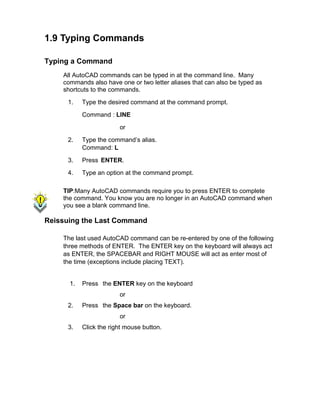


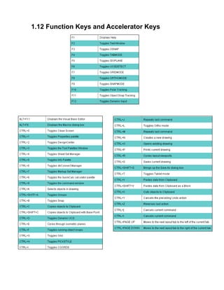


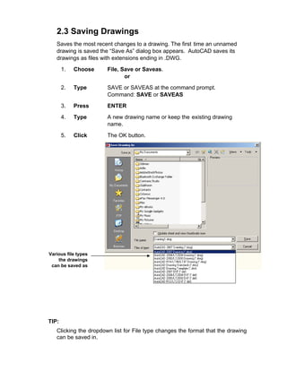
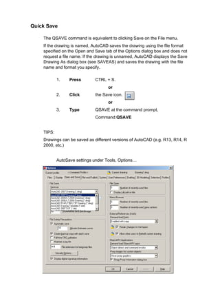


![3.1 Line Command
Creates single straight line segments
1. Choose Draw, Line.
or
2. Click the Line icon.
or
3. Type LINE from the command prompt
Command: LINE or L
4. Press ENTER
5. Pick From point: (point)
6. Pick Specify next point or [Close/Undo]:(point)
7. Pick Specify next point or [Close/Undo]:(point)
8. Press ENTER to end line sequence
or
9. Type U to undo the last segment
To point: U (undo)
or
10. Type C to create a closed polygon
To point : C (close)
TIPS:
• You can continue the previous line or arc by responding to
the From point: prompt with a space or ENTER.
• Choose the right mouse button for the line pop-up menu to
appear while in the line command](https://image.slidesharecdn.com/2dautocad2009-250517140534-a86645d2/85/2D_AutoCAD_2009-pdf-Engineering-Drawing-27-320.jpg)
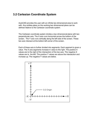


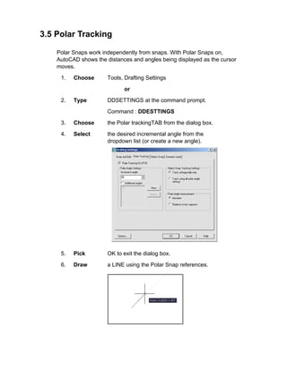

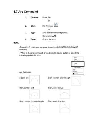


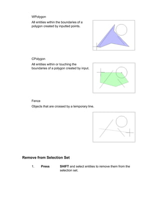


![6.1 SNAP Command
1. Choose Tools, Drafting Settings...
or
2. Type SNAP at the command prompt.
Command: SNAP or SN
3. Type One of the following options: Snap
spacing or
[ON/OFF/Aspect/Style/Type]:
Turn Snap On/OFF
1. Press Function Key F9 to turn the snap
ON/OFF.
or
2. Double Click SNAP on the Status Bar.
or
3. Press CTRL + B.
TIP:
Click with the right mouse button on the SNAP
option from the status bar as a shortcut to changing
the snap settings.](https://image.slidesharecdn.com/2dautocad2009-250517140534-a86645d2/85/2D_AutoCAD_2009-pdf-Engineering-Drawing-45-320.jpg)
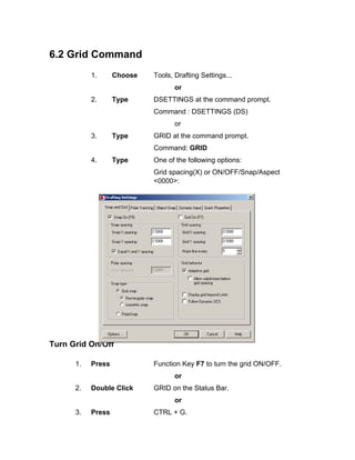

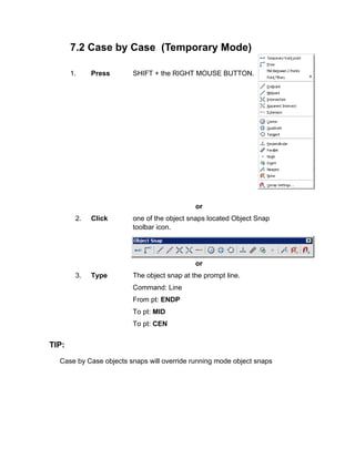


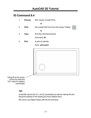


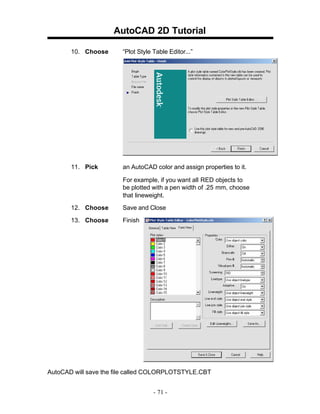
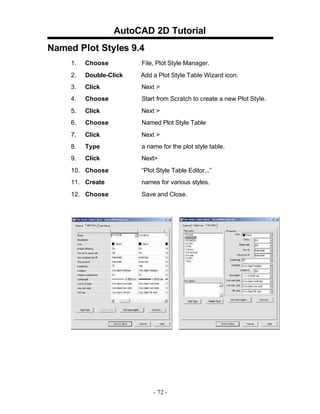


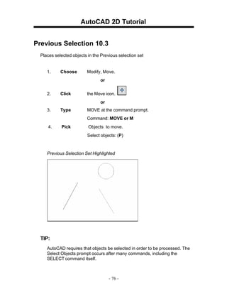


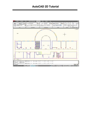

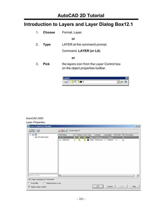


![AutoCAD 2D Tutorial
Lengthen 13.6
1. Choose Modify, LENGTHEN.
o
r
2. Type LENGTHENatthe command
prompt. Command: _lengthen
Selectanobjector[DElta/Percent/Total/
Enterdelta lengthor [Angle]<0.0000>:2
Select anobject tochange or [Undo]: pickobject
Object before lengthen
Object after lengthen
- 121 -](https://image.slidesharecdn.com/2dautocad2009-250517140534-a86645d2/85/2D_AutoCAD_2009-pdf-Engineering-Drawing-122-320.jpg)

![AutoCAD 2D Tutorial
Transparent Commands 14.1
Transparent commands are those started while another is in progress.
Precede transparent commands with an apostrophe.
1. Type LINE at the command prompt.
Command: LINE
Specify first point: (pick point)
Specify next point or [Undo]: 'zoom
>>Specify corner of window, enter a scale factor
(nX or nXP), or
[All/Center/Dynamic/Extents/Previous/Scale/ Window]
<real time>: (pick corner)
>>>>Specify opposite corner: (pick other corner)
Resuming LINE command.
Specify next point or [Undo]: (pick point)
TIP:
Commands thatdo notselect objects, create newobjects,or
end the drawing sessionusuallycanbeusedtransparently.
- 123 -](https://image.slidesharecdn.com/2dautocad2009-250517140534-a86645d2/85/2D_AutoCAD_2009-pdf-Engineering-Drawing-124-320.jpg)

![AutoCAD 2D Tutorial
Calculator (CAL Command) 14.3
Evaluates mathematicaland geometricexpressions
1. Type CAL atthe command
prompt. Command: cal
(or ‘cal) Initializing...>>
Expression:1+1
2
Numeric operators
( ) Groups expressions
^ Indicates exponentiation
* , / Multiplies, divides
+, - Adds, subtracts
Vector operators
( ) Groups expressions
& Determines the vector product of vectors (as a vector)
[a,b,c]&[x,y,z] = [ (b*z) - (c*y) , (c*x) - (a*z) , (a*y) - (b*x) ]
* Determines the scalar product of vectors (as a real number)
[a,b,c]*[x,y,z] = ax + by + cz
*, / Multiplies, divides a vector by a real number a*
[x,y,z] = [a*x,a*y,a*z]
+ , - Adds, subtracts vectors (points)
[a,b,c] + [x,y,z] = [a+x,b+y,c+z]
- 125 -](https://image.slidesharecdn.com/2dautocad2009-250517140534-a86645d2/85/2D_AutoCAD_2009-pdf-Engineering-Drawing-126-320.jpg)


![AutoCAD 2D Tutorial
Editing Multiple Polylines 15.3
1. Type the PEDIT atthe command
prompt. Command: PEDIT
Selectpolyline or [Multiple]:M
Pickmultiple polylinesto edit.
- 132 -](https://image.slidesharecdn.com/2dautocad2009-250517140534-a86645d2/85/2D_AutoCAD_2009-pdf-Engineering-Drawing-133-320.jpg)
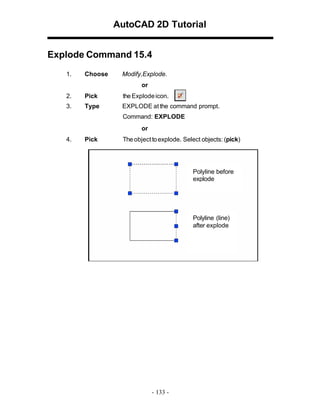
![AutoCAD 2D Tutorial
Turning Lines into Polylines 15.5
Use the PEDIT command to pick lines. AutoCAD will ask if you want to turn
these lines into polylines. You can then use the JOIN option under PEDIT to join
additional lines to the polyline.
1. Command: pedit
Select polyline or [Multiple]: pick line
Object selected is not a polyline
Do you want to turn it into one? <Y>
Enter an option [Close/Join/Width/Edit
vertex/Fit/Spline/Decurve/Ltype gen/Undo]: j
TIP:
• Lines and Arcs must have a common endpoint to join them together.
- 134 -](https://image.slidesharecdn.com/2dautocad2009-250517140534-a86645d2/85/2D_AutoCAD_2009-pdf-Engineering-Drawing-135-320.jpg)


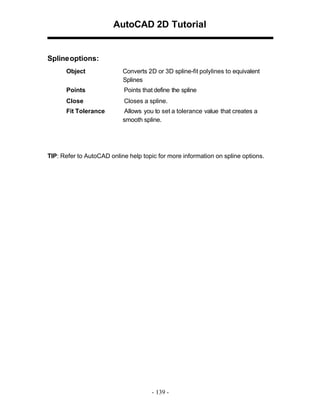

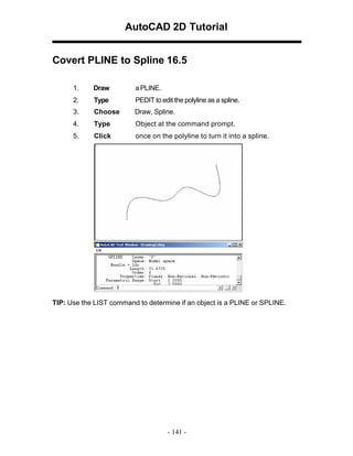


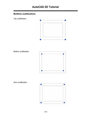


![AutoCAD 2D Tutorial
Construction Line 16.11
Creates aninfinite line.
1. Choose Draw,ConstructionLine
or
2. Choose the XLINE icon.
or
3. Type XLINE at the command prompt.
Command: XLINE
Specifyapointor[Hor/Ver/Ang/Bisect/Offset]:
XLINE Options
HOR Createsa horizontalxline passing throughaspecifiedpoint.
VER Createsa vertical xline passing throughaspecified point
ANG Createsan xline ata specifiedangle.
BISECT Createsanxline thatpasses throughthe selected angle vertex
and bisects the angle betweenthe first and second line
OFFSET Createsanxline paralleltoanotherobject.
- 149 -](https://image.slidesharecdn.com/2dautocad2009-250517140534-a86645d2/85/2D_AutoCAD_2009-pdf-Engineering-Drawing-150-320.jpg)


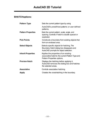


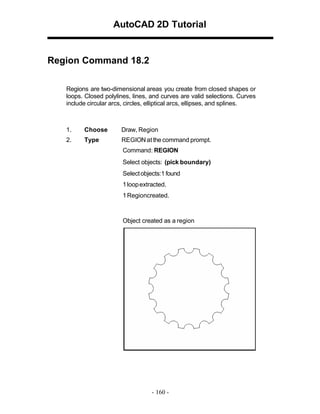
![AutoCAD 2D Tutorial
Mass Properties 18.3
Calculates the mass properties of regions orsolids.
1. Choose Tools,Inquiry, Region/MassProperties
2. Type MASSPROP atthe command prompt.
Command: MASSPROP
Select objects: (pick region)
---------------- REGIONS ----------------
Area: 11.1328
Perimeter: 16.3734
Bounding box: X: 3.1508 -- 7.1352
Y: 2.8950 -- 6.8942
Centroid: X: 5.1508
Y: 4.8946
Moments of inertia: X: 276.6983
Y: 305.3510
Product of inertia: XY: 280.6701
Radii of gyration: X: 4.9854
Y: 5.2372
Principal moments and X-Y directions about centroid:
I: 9.9891 along [1.0000 0.0000] J: 9.9891 along
[0.0000 1.0000]
Write analysis to a file? [Yes/No] <N>:
- 161 -](https://image.slidesharecdn.com/2dautocad2009-250517140534-a86645d2/85/2D_AutoCAD_2009-pdf-Engineering-Drawing-162-320.jpg)


![AutoCAD 2D Tutorial
Synchronize Attributes 19.9
Updatesallinstancesofaspecifiedblockwiththe currentattributes defined for
theblock
1. Open adrawing withattributes.
2. Type ATTSYNC atthe command prompt.
Command:ATTSYNC
3. Click the BlockAttribute Managericonfrom the
ModifyIItoolbar.
4. Press Enteranoption[?/Name/Select] <Select>:
enter and selecta blockwithattributes.
5. Press ATTSYNCblockcomputer?[Yes/No]<Yes>:
entertosynchronies. ATTSYNCcomplete.
- 172 -](https://image.slidesharecdn.com/2dautocad2009-250517140534-a86645d2/85/2D_AutoCAD_2009-pdf-Engineering-Drawing-173-320.jpg)


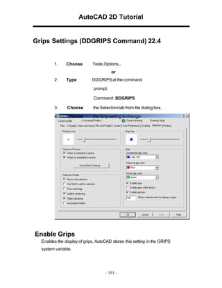


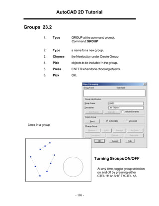

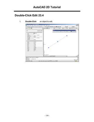


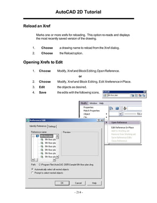


![AutoCAD 2D Tutorial
Image Transparency
1. Choose Modify, Object, Image,Transparency.
2. Choose a raster image file edit.
3. Type ONor OFF toturnanimage’stransparency onoroff.
Erasing Images
1. Click once onthe image to remove.
2. Choose Edit,Cut.
Imagequality
1. Type IMAGEQUALITY at the command prompt.
Command: imagequality
Enter image quality setting [High/Draft] <High>:
- 220 -](https://image.slidesharecdn.com/2dautocad2009-250517140534-a86645d2/85/2D_AutoCAD_2009-pdf-Engineering-Drawing-221-320.jpg)


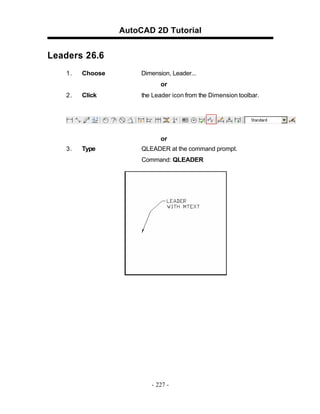


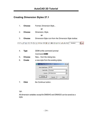

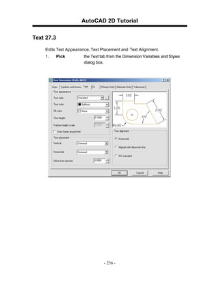


![AutoCAD 2D Tutorial
Dimension Overrride 27.9
1. Choose Dimension, Override.
2. Type a dimension setting to change (i.e. DIMSE1 which
suppresses the first extension line).
Command: _dimoverride
Enter dimension variable name to override or [Clear
overrides]: dimse1
3. Set the new value.
Enter new value for dimension variable <Off>: on
4. Press enter.
5. Pick the dimension to override.
- 242 -](https://image.slidesharecdn.com/2dautocad2009-250517140534-a86645d2/85/2D_AutoCAD_2009-pdf-Engineering-Drawing-244-320.jpg)
![AutoCAD 2D Tutorial
Dimension Variables 27.10
1. Type SETVAR at the command prompt.
Command: SETVAR
Enter variable name or [?]: ?
Enter variable(s) to list <*>: dim*
DIMADEC 0
DIMALT OFF
DIMALTD 2
DIMALTF 25.4000
DIMALTRND 0.0000
DIMALTTD 2
DIMALTTZ 0
DIMALTU 2
DIMALTZ 0
DIMAPOST ""
DIMASO ON
DIMASSOC 1
DIMASZ 0.1800
DIMATFIT 3
DIMAUNIT 0
DIMAZIN 0
DIMBLK "ArchTick"
DIMBLK1 ""
DIMBLK2 ""
DIMCEN 0.0900
DIMCLRD 0
DIMCLRE 0
DIMCLRT 5
DIMDEC 1
DIMDLE 0.1250
DIMDLI 0.5000
- 243 -](https://image.slidesharecdn.com/2dautocad2009-250517140534-a86645d2/85/2D_AutoCAD_2009-pdf-Engineering-Drawing-245-320.jpg)


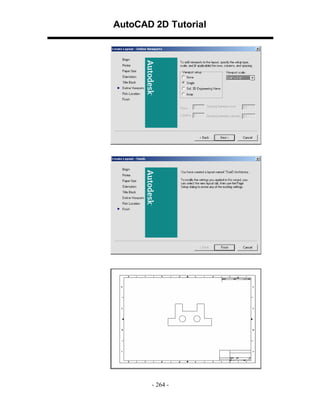


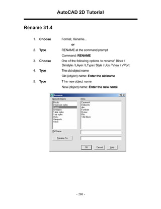


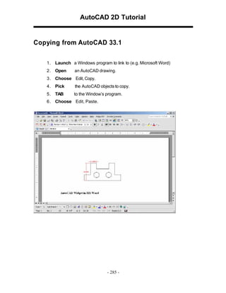


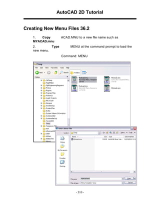


![AutoCAD 2D Tutorial
39.6 Revision Cloud
1. Choose Draw, Revcloud
or
2. Type REVCLOUD at the command prompt.
Command: revcloud
Minimum arc length: 0.5000
Maximum arc length: 0.5000
Specify start point or [Arc length/Object]
<Object>: Guide crosshairs along cloud path...
Revision cloud finished.
or
3. Click the Revcloud icon from the draw menu.
- 337 -](https://image.slidesharecdn.com/2dautocad2009-250517140534-a86645d2/85/2D_AutoCAD_2009-pdf-Engineering-Drawing-334-320.jpg)
![AutoCAD 2D Tutorial
39.8 Wipeout
Creates a polygonal area that masks underlying objects with the
current background color. This area is bounded by the wipeout
frame. You can turn on the wipeout frame for editing and turn it off for
plotting.
1. Choose Draw, Wipeout
or
2. Type WIPEOUT at the command prompt.
Command: _wipeout
Specify first point or [Frames/Polyline] <Polyline>:
Select a closed polyline:
- 338 -](https://image.slidesharecdn.com/2dautocad2009-250517140534-a86645d2/85/2D_AutoCAD_2009-pdf-Engineering-Drawing-335-320.jpg)