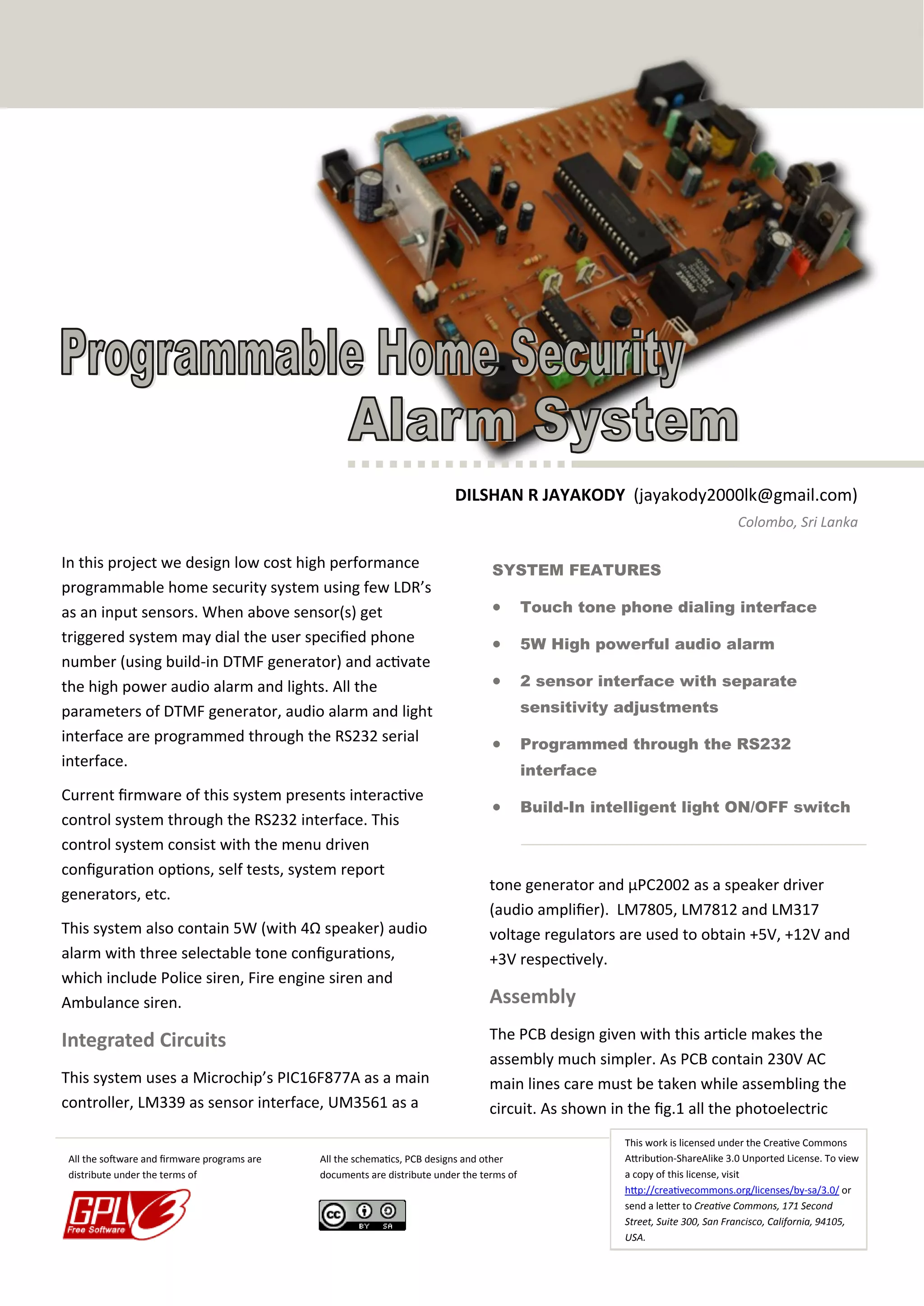
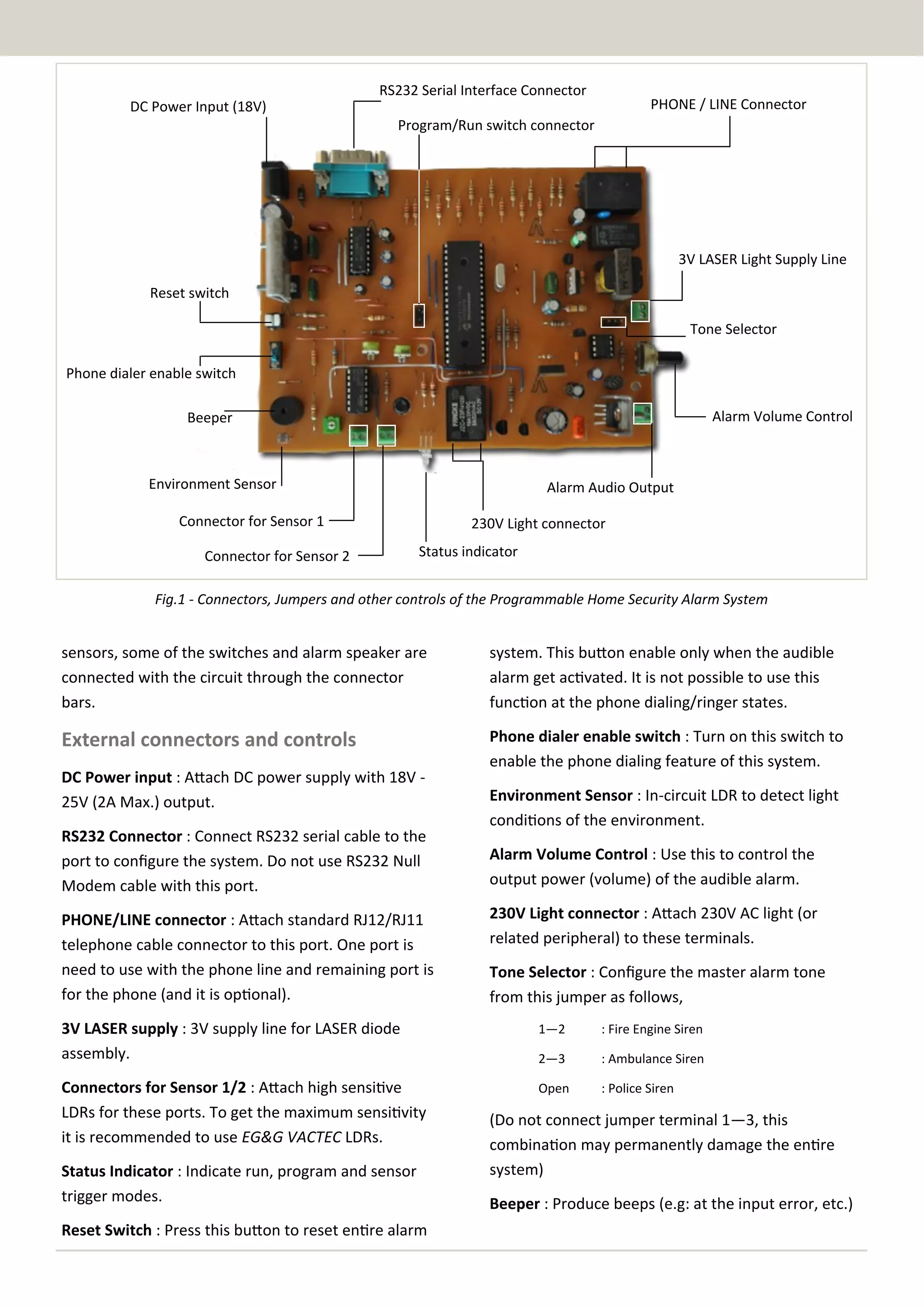
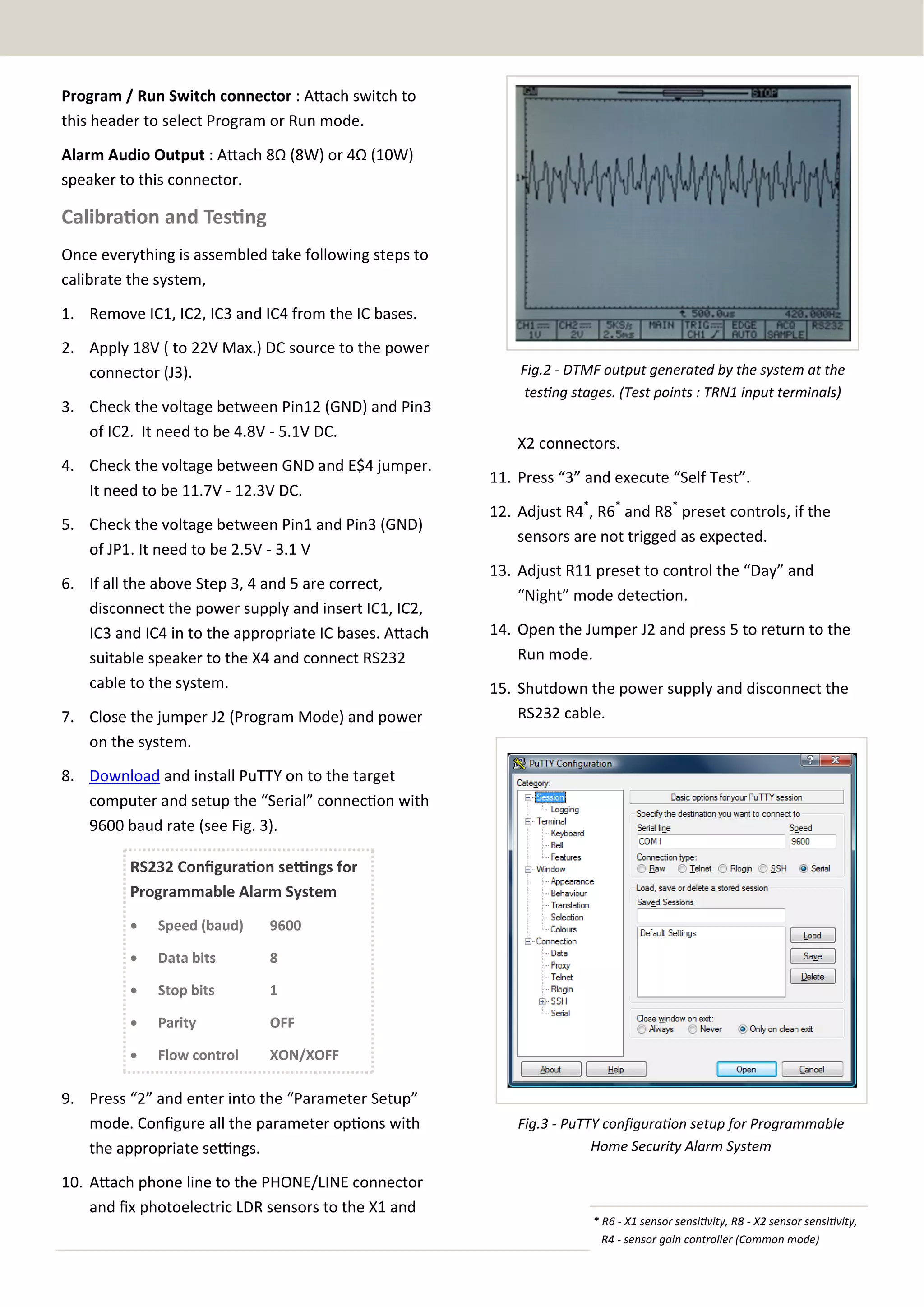
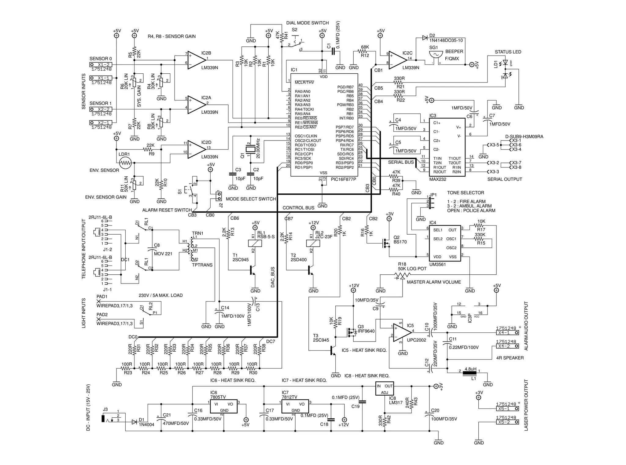
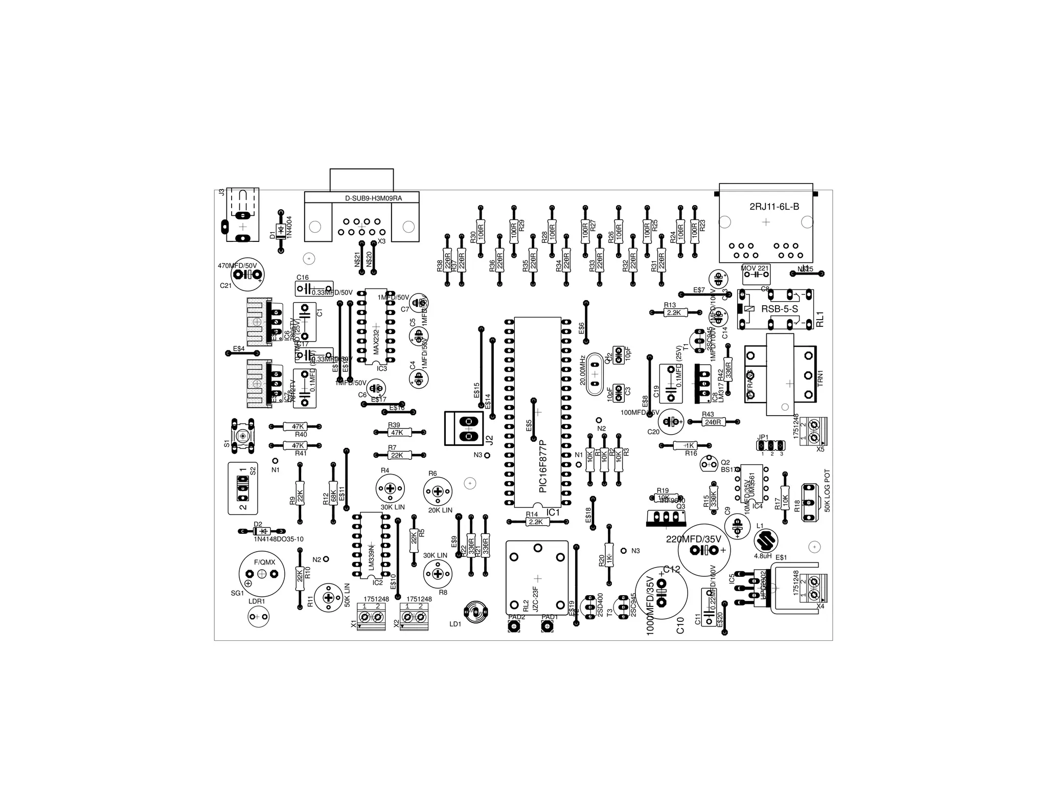
DILSHAN R JAYAKODY (jayakody2000lk@gmail.com)
Colombo, Sri Lanka

In this project we design low cost high performance
programmable home security system using few LDR’s
as an input sensors. When above sensor(s) get
triggered system may dial the user specified phone
number (using build-in DTMF generator) and activate
the high power audio alarm and lights. All the
parameters of DTMF generator, audio alarm and light
interface are programmed through the RS232 serial
interface.

SYSTEM FEATURES

Current firmware of this system presents interactive
control system through the RS232 interface. This
control system consist with the menu driven
configuration options, self tests, system report
generators, etc.



This system also contain 5W (with 4Ω speaker) audio
alarm with three selectable tone configurations,
which include Police siren, Fire engine siren and
Ambulance siren.

Integrated Circuits
This system uses a Microchip’s PIC16F877A as a main
controller, LM339 as sensor interface, UM3561 as a
All the software and firmware programs are
distribute under the terms of



Touch tone phone dialing interface



5W High powerful audio alarm



2 sensor interface with separate
sensitivity adjustments



Programmed through the RS232
interface
Build-In intelligent light ON/OFF switch

tone generator and µPC2002 as a speaker driver
(audio amplifier). LM7805, LM7812 and LM317
voltage regulators are used to obtain +5V, +12V and
+3V respectively.

Assembly
The PCB design given with this article makes the
assembly much simpler. As PCB contain 230V AC
main lines care must be taken while assembling the
circuit. As shown in the fig.1 all the photoelectric

All the schematics, PCB designs and other
documents are distribute under the terms of

This work is licensed under the Creative Commons
Attribution-ShareAlike 3.0 Unported License. To view
a copy of this license, visit
http://creativecommons.org/licenses/by-sa/3.0/ or
send a letter to Creative Commons, 171 Second
Street, Suite 300, San Francisco, California, 94105,
USA.
RS232 Serial Interface Connector

PHONE / LINE Connector

DC Power Input (18V)
Program/Run switch connector

3V LASER Light Supply Line
Reset switch
Tone Selector
Phone dialer enable switch
Alarm Volume Control

Beeper

Environment Sensor

Alarm Audio Output

Connector for Sensor 1
Connector for Sensor 2

230V Light connector
Status indicator

Fig.1 - Connectors, Jumpers and other controls of the Programmable Home Security Alarm System

sensors, some of the switches and alarm speaker are
connected with the circuit through the connector
bars.

system. This button enable only when the audible
alarm get activated. It is not possible to use this
function at the phone dialing/ringer states.

External connectors and controls

Phone dialer enable switch : Turn on this switch to
enable the phone dialing feature of this system.

DC Power input : Attach DC power supply with 18V 25V (2A Max.) output.
RS232 Connector : Connect RS232 serial cable to the
port to configure the system. Do not use RS232 Null
Modem cable with this port.
PHONE/LINE connector : Attach standard RJ12/RJ11
telephone cable connector to this port. One port is
need to use with the phone line and remaining port is
for the phone (and it is optional).

Environment Sensor : In-circuit LDR to detect light
conditions of the environment.
Alarm Volume Control : Use this to control the
output power (volume) of the audible alarm.
230V Light connector : Attach 230V AC light (or
related peripheral) to these terminals.
Tone Selector : Configure the master alarm tone
from this jumper as follows,

3V LASER supply : 3V supply line for LASER diode
assembly.

1—2

: Fire Engine Siren

2—3

: Ambulance Siren

Connectors for Sensor 1/2 : Attach high sensitive
LDRs for these ports. To get the maximum sensitivity
it is recommended to use EG&G VACTEC LDRs.

Open

: Police Siren

Status Indicator : Indicate run, program and sensor
trigger modes.
Reset Switch : Press this button to reset entire alarm

(Do not connect jumper terminal 1—3, this
combination may permanently damage the entire
system)
Beeper : Produce beeps (e.g: at the input error, etc.)
Program / Run Switch connector : Attach switch to
this header to select Program or Run mode.
Alarm Audio Output : Attach 8Ω (8W) or 4Ω (10W)
speaker to this connector.

Calibration and Testing
Once everything is assembled take following steps to
calibrate the system,
1. Remove IC1, IC2, IC3 and IC4 from the IC bases.
2. Apply 18V ( to 22V Max.) DC source to the power
connector (J3).
3. Check the voltage between Pin12 (GND) and Pin3
of IC2. It need to be 4.8V - 5.1V DC.
4. Check the voltage between GND and E$4 jumper.
It need to be 11.7V - 12.3V DC.
5. Check the voltage between Pin1 and Pin3 (GND)
of JP1. It need to be 2.5V - 3.1 V
6. If all the above Step 3, 4 and 5 are correct,
disconnect the power supply and insert IC1, IC2,
IC3 and IC4 in to the appropriate IC bases. Attach
suitable speaker to the X4 and connect RS232
cable to the system.
7. Close the jumper J2 (Program Mode) and power
on the system.

Fig.2 - DTMF output generated by the system at the
testing stages. (Test points : TRN1 input terminals)

X2 connectors.
11. Press “3” and execute “Self Test”.
12. Adjust R4*, R6* and R8* preset controls, if the
sensors are not trigged as expected.
13. Adjust R11 preset to control the “Day” and
“Night” mode detection.
14. Open the Jumper J2 and press 5 to return to the
Run mode.
15. Shutdown the power supply and disconnect the
RS232 cable.

8. Download and install PuTTY on to the target
computer and setup the “Serial” connection with
9600 baud rate (see Fig. 3).
RS232 Configuration settings for
Programmable Alarm System


Speed (baud)

9600



Data bits

8



Stop bits

1



Parity

OFF



Flow control

XON/XOFF

9. Press “2” and enter into the “Parameter Setup”
mode. Configure all the parameter options with
the appropriate settings.
10. Attach phone line to the PHONE/LINE connector
and fix photoelectric LDR sensors to the X1 and

Fig.3 - PuTTY configuration setup for Programmable
Home Security Alarm System

* R6 - X1 sensor sensitivity, R8 - X2 sensor sensitivity,
R4 - sensor gain controller (Common mode)
Parts List
C1, C18, C19

0.1µF (25V)

IC1

PIC16F877A

C2, C3

10pF

IC2

LM339N

C11

0.22µF (100V)

IC3

MAX232

C16, C17

0.33µF (50V)

IC4

UM3561

C4, C5, C6, C7

1µF (50V)

IC5

µPC2002 / TDA2002

C13, C14

1µF (100V)

IC6

7805TV

C9

10µF (35V)

IC7

7812TV

C10

1000µF (35V)

IC8

LM317

C12

220µF (35V)

D1

1N4004 Diode

C20

100µF (35V)

D2

1N4148 Diode

C21

470µF (35V)

C8

VE09-0151 MOV

R1, R2, R3, R1, R19

10K

T1, T3

2SC945

R5, R7, R9, R10

22K

T2

2SD400

R12

68K

Q2

BS170

R13, R14

2.2K

Q3

IRF9640

R15

330K

Q1

20.00MHz Crystal

R16, R20

1K

R4, R8

30K (LIN) Potentiometer

R21, R22, R42

330Ω

R6

20K (LIN) Potentiometer

R23, R24, R25, R26,
R27,R28, R29, R30

100Ω

R11

50K (LIN) Potentiometer

R18

50K (LOG) Gang Potentiometer

R31, R32, R33, R34,
R35, R36, R37, R38

220Ω

L1

4.8 µH Inductor

R39, R40, R41

47K

LDR1

VT90N2 LDR

R43

240Ω (0.5 W)

LD1

5mm Tri-Color LED

TRN1

600Ω : 600Ω isolation
transformer

JP1

3 Pin Jumper Header

J1

Tyco Electronics 2RJ11-6L-B

SG1

F/QMX Buzzer

J2

1X2MTA header

RL1

SHINMEI RSB-5-S Relay

J3

DCJ0303 DC Jack connector

RL2

FANGKE JZC-23F 12V Relay
(220V 5A)

X3

H3M09RA D-SUB9 connector

X1, X2, X4, X5

Phoenix 350 connector

S1

B3F-10XX - push on switch

SPK

8Ω (8W) or 4Ω (10W) Speaker

S2

M251 SPDT micro switch

All the resistors are 1/4W unless otherwise specified
0.1MFD (25V)

3

LM339N
3

11

22K

2

IC2D

20.00MHz

GND

Q1

LM339N

1

13
10

R9

13
14
15
16
17
18
19
20

+5V
10pF

1MFD/50V

RL1

L2
M1

32
11

CB3

GND

R40

1 - 2 : FIRE ALARM
3 - 2 : AMBUL. ALARM
OPEN : POLICE ALARM

1K

R16

1

Q2
BS170

10K

SEL1

OUT

SEL2

3

OSC1

5

VDD

R17
330K

7

R15

8
2

VSS

MASTER ALARM VOLUME

+12V
GND

GND

+5V
GND

R27

R28

R29

R30

C16
C21
D1
1N4004

470MFD/50V

1

C17

GND

VI

0.33MFD/50V

IC8
LM317

C19

0.1MFD (25V)
C18

+12V

ALARM AUDIO OUTPUT

C10

C20

GND

0.33MFD/50V
+5V

0.1MFD (25V)
3

GND
+3V

ADJ
VO

2

1
2
3

3

2

J3

IC7
7812TV

OUT

330R

IC6
7805TV

4.8uH 1
L1

IC7 - HEAT SINK REQ.
IN

VO

4R SPEAKER
2

IC6 - HEAT SINK REQ.

VI

0.22MFD/100V

GND IC8 - HEAT SINK REQ.

GND

1

C11

+

R26

+

100MFD/35V

GND

GND

LASER POWER OUTPUT

R25

GND

+3V

R24

5

100R

R23

C12

100R

GND

16
VCC

R43

100R

UPC2002

240R

100R

IC5 - HEAT SINK REQ.

R42

100R

4

GND

IC3P

C13

100R

R38

220R

R37

220R

R36

220R

R35

220R

R34

220R

R33

220R

R32

220R

R31

220R

100R

DC7

IC5

3

15

2

T3
2SC945

DC0

100R

1

Q3
IRF9640

12

220MFD/35V

GND GND

3

WIREPAD3,17/1,3

R19

S1

1MFD/100V

C9
10K

P1

PAD2

1MFD/100V

RL2

10MFD/35V
C14

1000MFD/35V

230V / 5A MAX. LOAD
O1

SERIAL OUTPUT

IC4
6

X3-7
X3-8

X3-3

R18
UM3561
50K LOG POT

GND

WIREPAD3,17/1,3

X3-2

TONE SELECTOR

1 JP1
2
3

GND

D-SUB9-H3M09RA
X3-1
X3-6
X3-4

GND

MAX232

OSC2

DAC_BUS

N2

J1-1

14
7
13
8

T1IN
T1OUT
T2IN
T2OUT
R1OUT
R1IN
R2OUT
R2IN

R39
47K

T2
2SD400

TPTRANS

PAD1

RL2
JZC-23F

1K

K1

R14

T1
2SC945

M2

C2

C2-

K2

MOV 221

X3-5

11
10
12
9

SERIAL BUS

6

VC2+

5

1MFD/50V

CB2

CB2

K2

H2

2.2K

H1

C8

V+

4

1MFD/50V

2

C1-

GND

C7

C6

C1+

3

C5

+12V

RL1
RSB-5-S

K1

L1

R13

2.2K

N1

TRN1

D2

CB7
R20

RL1

D1

C1

DC1

1

+3V
CB6
+5V

J1-2

LIGHT INPUTS

IC3
C4

CONTROL BUS GND

CB0

GND

1MFD/50V

PIC16F877P

GND

J2

ALARM RESET SWITCH
CB3

6
5
4
3
2
1

DC - INPUT (15V - 25V)

R22

MODE SELECT SWITCH

GND

2RJ11-6L-B

6
5
4
3
2
1

CB4

3
4

GND

TELEPHONE INPUT/OUTPUT

GND

1

S1

ENV. SENSOR GAIN

2RJ11-6L-B

10pF

+

R21
330R

47K

1
2

R10

22K

3
1

R11
50K LIN

2

C2

CB5

30
29
28
27
26
25
24
23
22
21

PSP7/RD7
PSP6/RD6
PSP5/RD5
PSP4/RD4
RX/RC7
TX/RC6
SDO/RC5
SDI/RC4
RD3/PSP3
RD2/PSP2

OSC1/CLKIN
OSC2/CLKOUT
RC0/T1OSO
RC1/T1OSI
RC2/CCP1
RC3/SCK
RD0/PSP0
RD1/PSP1
VSS
31
12

C3

ENV. SENSOR

40
39
38
37
36
35
34
33

PGD/RB7
PGC/RB6
RB5
RB4
PGM/RB3
RB2
RB1
INT/RB0

RA0/AN0
RA1/AN1
RA2/AN2
RA3/AN3
RA4/T0CKI
RA5/AN4
RE0/RD/AN5
RE1/WR/AN6
RE2/CS/AN7

1

2

+5V

LDR1

-

LM339N

CB1

CB0

1

2

R8
30K LIN

1

SYS. GAIN

IC2A

5

STATUS LED

F/QMX

330R

MCLR/THV

2
3
4
5
6
7
8
9
10

4

22K

R7

1

GND

GND

GND GND

VDD
2

BEEPER

14
8

IC1

3

R4
30K LIN

3

R6
20K LIN

SENSOR INPUTS

LM339N

SENSOR 1

SG1
IC2C

9

red

R3

6

10K

1

2

68K
R12

10K
R1

7

10K
R2

SENSOR 0

22K

R5

2

IC2B

D2
1N4148DO35-10

green

1

+5V

LD1

GND

+5V

+5V

S2

+5V

R4, R8 - SENSOR GAIN

C1

+5V

R41

+5V

47K

DIAL MODE SWITCH
+5V
LDR1
1751248
IC2

1751248
R8

LD1
PAD2
PAD1

C12

N3

TRN1

JP1
1

IC4

2
3

RL1

RSB-5-S

50K LOG POT

1K
R16
1751248

R43
240R

R18

C20

R17
10K

TPTRANS

R31
220R

R32
220R

R33
220R

R34
220R

R35
220R

R36
220R

R38
220R
R37
220R

N$20

N$21

MOV 221

1751248

C9

Q2
BS170
10MFD/35V
UM3561

A O I
2SC945
1MFD/100V 1MFD/100V
IC8
LM317 R42
C14
C13
330R

0.1MFD (25V)
T1

C19

E$8

10pF

Q1
C2

E$6

E$7

UPC2002

R19
10K
IRF9640
Q3
R15
330K

100MFD/35V

IC5

0.22MFD/100V

IC1

C3

10pF

20.00MHz

1MFD/50V

1MFD/50V

R13
2.2K

E$20

30K LIN
R14
2.2K

10K
R1
10K
R2
10K
R3

MAX232

C21

C11

D2

C10

20K LIN
N1

2SC945

N3
N2

1000MFD/35V

R6

30K LIN

R20
1K

R7
22K

E$18

47K
R41

2SD400
T3

E$16

PIC16F877P

E$17

E$19
T2

R39
47K
E$5

C6
C4

IC3

J2

1MFD/50V

E$15

E$12

1N4004

D1

100R
R23

R24
100R

100R
R25

R26
100R

100R
R27

R28
100R

100R
R29

R30
100R

X3

E$14

0.33MFD/50V

E$13

C5

C1

E$2 2 3
1

C7

E$9
R22
330R
R21
330R

C17

IC6
7805TV
0.1MFD (25V)

0.1MFD (25V)

IC7
C18
7812TV

E$3 2 3
1

1MFD/50V

RL2
JZC-23F

1N4148DO35-10
22K
R5

4

0.33MFD/50V

E$10

N2
LM339N

N1
R4

R12
68K
E$11

3

470MFD/50V

X2

SG1
50K LIN

F/QMX

X1

R9
22K

1
S2

2
E$4

R11

22K
R10

2

S1

47K
R40

1

J3

D-SUB9-H3M09RA

2RJ11-6L-B

C16
N$25
J1

C8

X5

220MFD/35V
L1

4.8uH E$1

X4
Programmable Home Security Alarm System

Programmable Home Security Alarm System

  • 1.
    DILSHAN R JAYAKODY(jayakody2000lk@gmail.com) Colombo, Sri Lanka In this project we design low cost high performance programmable home security system using few LDR’s as an input sensors. When above sensor(s) get triggered system may dial the user specified phone number (using build-in DTMF generator) and activate the high power audio alarm and lights. All the parameters of DTMF generator, audio alarm and light interface are programmed through the RS232 serial interface. SYSTEM FEATURES Current firmware of this system presents interactive control system through the RS232 interface. This control system consist with the menu driven configuration options, self tests, system report generators, etc.  This system also contain 5W (with 4Ω speaker) audio alarm with three selectable tone configurations, which include Police siren, Fire engine siren and Ambulance siren. Integrated Circuits This system uses a Microchip’s PIC16F877A as a main controller, LM339 as sensor interface, UM3561 as a All the software and firmware programs are distribute under the terms of  Touch tone phone dialing interface  5W High powerful audio alarm  2 sensor interface with separate sensitivity adjustments  Programmed through the RS232 interface Build-In intelligent light ON/OFF switch tone generator and µPC2002 as a speaker driver (audio amplifier). LM7805, LM7812 and LM317 voltage regulators are used to obtain +5V, +12V and +3V respectively. Assembly The PCB design given with this article makes the assembly much simpler. As PCB contain 230V AC main lines care must be taken while assembling the circuit. As shown in the fig.1 all the photoelectric All the schematics, PCB designs and other documents are distribute under the terms of This work is licensed under the Creative Commons Attribution-ShareAlike 3.0 Unported License. To view a copy of this license, visit http://creativecommons.org/licenses/by-sa/3.0/ or send a letter to Creative Commons, 171 Second Street, Suite 300, San Francisco, California, 94105, USA.
  • 2.
    RS232 Serial InterfaceConnector PHONE / LINE Connector DC Power Input (18V) Program/Run switch connector 3V LASER Light Supply Line Reset switch Tone Selector Phone dialer enable switch Alarm Volume Control Beeper Environment Sensor Alarm Audio Output Connector for Sensor 1 Connector for Sensor 2 230V Light connector Status indicator Fig.1 - Connectors, Jumpers and other controls of the Programmable Home Security Alarm System sensors, some of the switches and alarm speaker are connected with the circuit through the connector bars. system. This button enable only when the audible alarm get activated. It is not possible to use this function at the phone dialing/ringer states. External connectors and controls Phone dialer enable switch : Turn on this switch to enable the phone dialing feature of this system. DC Power input : Attach DC power supply with 18V 25V (2A Max.) output. RS232 Connector : Connect RS232 serial cable to the port to configure the system. Do not use RS232 Null Modem cable with this port. PHONE/LINE connector : Attach standard RJ12/RJ11 telephone cable connector to this port. One port is need to use with the phone line and remaining port is for the phone (and it is optional). Environment Sensor : In-circuit LDR to detect light conditions of the environment. Alarm Volume Control : Use this to control the output power (volume) of the audible alarm. 230V Light connector : Attach 230V AC light (or related peripheral) to these terminals. Tone Selector : Configure the master alarm tone from this jumper as follows, 3V LASER supply : 3V supply line for LASER diode assembly. 1—2 : Fire Engine Siren 2—3 : Ambulance Siren Connectors for Sensor 1/2 : Attach high sensitive LDRs for these ports. To get the maximum sensitivity it is recommended to use EG&G VACTEC LDRs. Open : Police Siren Status Indicator : Indicate run, program and sensor trigger modes. Reset Switch : Press this button to reset entire alarm (Do not connect jumper terminal 1—3, this combination may permanently damage the entire system) Beeper : Produce beeps (e.g: at the input error, etc.)
  • 3.
    Program / RunSwitch connector : Attach switch to this header to select Program or Run mode. Alarm Audio Output : Attach 8Ω (8W) or 4Ω (10W) speaker to this connector. Calibration and Testing Once everything is assembled take following steps to calibrate the system, 1. Remove IC1, IC2, IC3 and IC4 from the IC bases. 2. Apply 18V ( to 22V Max.) DC source to the power connector (J3). 3. Check the voltage between Pin12 (GND) and Pin3 of IC2. It need to be 4.8V - 5.1V DC. 4. Check the voltage between GND and E$4 jumper. It need to be 11.7V - 12.3V DC. 5. Check the voltage between Pin1 and Pin3 (GND) of JP1. It need to be 2.5V - 3.1 V 6. If all the above Step 3, 4 and 5 are correct, disconnect the power supply and insert IC1, IC2, IC3 and IC4 in to the appropriate IC bases. Attach suitable speaker to the X4 and connect RS232 cable to the system. 7. Close the jumper J2 (Program Mode) and power on the system. Fig.2 - DTMF output generated by the system at the testing stages. (Test points : TRN1 input terminals) X2 connectors. 11. Press “3” and execute “Self Test”. 12. Adjust R4*, R6* and R8* preset controls, if the sensors are not trigged as expected. 13. Adjust R11 preset to control the “Day” and “Night” mode detection. 14. Open the Jumper J2 and press 5 to return to the Run mode. 15. Shutdown the power supply and disconnect the RS232 cable. 8. Download and install PuTTY on to the target computer and setup the “Serial” connection with 9600 baud rate (see Fig. 3). RS232 Configuration settings for Programmable Alarm System  Speed (baud) 9600  Data bits 8  Stop bits 1  Parity OFF  Flow control XON/XOFF 9. Press “2” and enter into the “Parameter Setup” mode. Configure all the parameter options with the appropriate settings. 10. Attach phone line to the PHONE/LINE connector and fix photoelectric LDR sensors to the X1 and Fig.3 - PuTTY configuration setup for Programmable Home Security Alarm System * R6 - X1 sensor sensitivity, R8 - X2 sensor sensitivity, R4 - sensor gain controller (Common mode)
  • 4.
    Parts List C1, C18,C19 0.1µF (25V) IC1 PIC16F877A C2, C3 10pF IC2 LM339N C11 0.22µF (100V) IC3 MAX232 C16, C17 0.33µF (50V) IC4 UM3561 C4, C5, C6, C7 1µF (50V) IC5 µPC2002 / TDA2002 C13, C14 1µF (100V) IC6 7805TV C9 10µF (35V) IC7 7812TV C10 1000µF (35V) IC8 LM317 C12 220µF (35V) D1 1N4004 Diode C20 100µF (35V) D2 1N4148 Diode C21 470µF (35V) C8 VE09-0151 MOV R1, R2, R3, R1, R19 10K T1, T3 2SC945 R5, R7, R9, R10 22K T2 2SD400 R12 68K Q2 BS170 R13, R14 2.2K Q3 IRF9640 R15 330K Q1 20.00MHz Crystal R16, R20 1K R4, R8 30K (LIN) Potentiometer R21, R22, R42 330Ω R6 20K (LIN) Potentiometer R23, R24, R25, R26, R27,R28, R29, R30 100Ω R11 50K (LIN) Potentiometer R18 50K (LOG) Gang Potentiometer R31, R32, R33, R34, R35, R36, R37, R38 220Ω L1 4.8 µH Inductor R39, R40, R41 47K LDR1 VT90N2 LDR R43 240Ω (0.5 W) LD1 5mm Tri-Color LED TRN1 600Ω : 600Ω isolation transformer JP1 3 Pin Jumper Header J1 Tyco Electronics 2RJ11-6L-B SG1 F/QMX Buzzer J2 1X2MTA header RL1 SHINMEI RSB-5-S Relay J3 DCJ0303 DC Jack connector RL2 FANGKE JZC-23F 12V Relay (220V 5A) X3 H3M09RA D-SUB9 connector X1, X2, X4, X5 Phoenix 350 connector S1 B3F-10XX - push on switch SPK 8Ω (8W) or 4Ω (10W) Speaker S2 M251 SPDT micro switch All the resistors are 1/4W unless otherwise specified
  • 5.
    0.1MFD (25V) 3 LM339N 3 11 22K 2 IC2D 20.00MHz GND Q1 LM339N 1 13 10 R9 13 14 15 16 17 18 19 20 +5V 10pF 1MFD/50V RL1 L2 M1 32 11 CB3 GND R40 1 -2 : FIRE ALARM 3 - 2 : AMBUL. ALARM OPEN : POLICE ALARM 1K R16 1 Q2 BS170 10K SEL1 OUT SEL2 3 OSC1 5 VDD R17 330K 7 R15 8 2 VSS MASTER ALARM VOLUME +12V GND GND +5V GND R27 R28 R29 R30 C16 C21 D1 1N4004 470MFD/50V 1 C17 GND VI 0.33MFD/50V IC8 LM317 C19 0.1MFD (25V) C18 +12V ALARM AUDIO OUTPUT C10 C20 GND 0.33MFD/50V +5V 0.1MFD (25V) 3 GND +3V ADJ VO 2 1 2 3 3 2 J3 IC7 7812TV OUT 330R IC6 7805TV 4.8uH 1 L1 IC7 - HEAT SINK REQ. IN VO 4R SPEAKER 2 IC6 - HEAT SINK REQ. VI 0.22MFD/100V GND IC8 - HEAT SINK REQ. GND 1 C11 + R26 + 100MFD/35V GND GND LASER POWER OUTPUT R25 GND +3V R24 5 100R R23 C12 100R GND 16 VCC R43 100R UPC2002 240R 100R IC5 - HEAT SINK REQ. R42 100R 4 GND IC3P C13 100R R38 220R R37 220R R36 220R R35 220R R34 220R R33 220R R32 220R R31 220R 100R DC7 IC5 3 15 2 T3 2SC945 DC0 100R 1 Q3 IRF9640 12 220MFD/35V GND GND 3 WIREPAD3,17/1,3 R19 S1 1MFD/100V C9 10K P1 PAD2 1MFD/100V RL2 10MFD/35V C14 1000MFD/35V 230V / 5A MAX. LOAD O1 SERIAL OUTPUT IC4 6 X3-7 X3-8 X3-3 R18 UM3561 50K LOG POT GND WIREPAD3,17/1,3 X3-2 TONE SELECTOR 1 JP1 2 3 GND D-SUB9-H3M09RA X3-1 X3-6 X3-4 GND MAX232 OSC2 DAC_BUS N2 J1-1 14 7 13 8 T1IN T1OUT T2IN T2OUT R1OUT R1IN R2OUT R2IN R39 47K T2 2SD400 TPTRANS PAD1 RL2 JZC-23F 1K K1 R14 T1 2SC945 M2 C2 C2- K2 MOV 221 X3-5 11 10 12 9 SERIAL BUS 6 VC2+ 5 1MFD/50V CB2 CB2 K2 H2 2.2K H1 C8 V+ 4 1MFD/50V 2 C1- GND C7 C6 C1+ 3 C5 +12V RL1 RSB-5-S K1 L1 R13 2.2K N1 TRN1 D2 CB7 R20 RL1 D1 C1 DC1 1 +3V CB6 +5V J1-2 LIGHT INPUTS IC3 C4 CONTROL BUS GND CB0 GND 1MFD/50V PIC16F877P GND J2 ALARM RESET SWITCH CB3 6 5 4 3 2 1 DC - INPUT (15V - 25V) R22 MODE SELECT SWITCH GND 2RJ11-6L-B 6 5 4 3 2 1 CB4 3 4 GND TELEPHONE INPUT/OUTPUT GND 1 S1 ENV. SENSOR GAIN 2RJ11-6L-B 10pF + R21 330R 47K 1 2 R10 22K 3 1 R11 50K LIN 2 C2 CB5 30 29 28 27 26 25 24 23 22 21 PSP7/RD7 PSP6/RD6 PSP5/RD5 PSP4/RD4 RX/RC7 TX/RC6 SDO/RC5 SDI/RC4 RD3/PSP3 RD2/PSP2 OSC1/CLKIN OSC2/CLKOUT RC0/T1OSO RC1/T1OSI RC2/CCP1 RC3/SCK RD0/PSP0 RD1/PSP1 VSS 31 12 C3 ENV. SENSOR 40 39 38 37 36 35 34 33 PGD/RB7 PGC/RB6 RB5 RB4 PGM/RB3 RB2 RB1 INT/RB0 RA0/AN0 RA1/AN1 RA2/AN2 RA3/AN3 RA4/T0CKI RA5/AN4 RE0/RD/AN5 RE1/WR/AN6 RE2/CS/AN7 1 2 +5V LDR1 - LM339N CB1 CB0 1 2 R8 30K LIN 1 SYS. GAIN IC2A 5 STATUS LED F/QMX 330R MCLR/THV 2 3 4 5 6 7 8 9 10 4 22K R7 1 GND GND GND GND VDD 2 BEEPER 14 8 IC1 3 R4 30K LIN 3 R6 20K LIN SENSOR INPUTS LM339N SENSOR 1 SG1 IC2C 9 red R3 6 10K 1 2 68K R12 10K R1 7 10K R2 SENSOR 0 22K R5 2 IC2B D2 1N4148DO35-10 green 1 +5V LD1 GND +5V +5V S2 +5V R4, R8 - SENSOR GAIN C1 +5V R41 +5V 47K DIAL MODE SWITCH +5V
  • 6.
    LDR1 1751248 IC2 1751248 R8 LD1 PAD2 PAD1 C12 N3 TRN1 JP1 1 IC4 2 3 RL1 RSB-5-S 50K LOG POT 1K R16 1751248 R43 240R R18 C20 R17 10K TPTRANS R31 220R R32 220R R33 220R R34 220R R35 220R R36 220R R38 220R R37 220R N$20 N$21 MOV221 1751248 C9 Q2 BS170 10MFD/35V UM3561 A O I 2SC945 1MFD/100V 1MFD/100V IC8 LM317 R42 C14 C13 330R 0.1MFD (25V) T1 C19 E$8 10pF Q1 C2 E$6 E$7 UPC2002 R19 10K IRF9640 Q3 R15 330K 100MFD/35V IC5 0.22MFD/100V IC1 C3 10pF 20.00MHz 1MFD/50V 1MFD/50V R13 2.2K E$20 30K LIN R14 2.2K 10K R1 10K R2 10K R3 MAX232 C21 C11 D2 C10 20K LIN N1 2SC945 N3 N2 1000MFD/35V R6 30K LIN R20 1K R7 22K E$18 47K R41 2SD400 T3 E$16 PIC16F877P E$17 E$19 T2 R39 47K E$5 C6 C4 IC3 J2 1MFD/50V E$15 E$12 1N4004 D1 100R R23 R24 100R 100R R25 R26 100R 100R R27 R28 100R 100R R29 R30 100R X3 E$14 0.33MFD/50V E$13 C5 C1 E$2 2 3 1 C7 E$9 R22 330R R21 330R C17 IC6 7805TV 0.1MFD (25V) 0.1MFD (25V) IC7 C18 7812TV E$3 2 3 1 1MFD/50V RL2 JZC-23F 1N4148DO35-10 22K R5 4 0.33MFD/50V E$10 N2 LM339N N1 R4 R12 68K E$11 3 470MFD/50V X2 SG1 50K LIN F/QMX X1 R9 22K 1 S2 2 E$4 R11 22K R10 2 S1 47K R40 1 J3 D-SUB9-H3M09RA 2RJ11-6L-B C16 N$25 J1 C8 X5 220MFD/35V L1 4.8uH E$1 X4