Download to read offline
![SECTION 7 (THERMAL RELATIONS)
This section outlines the basic thermal relationships common to most tubular heat transfer equipment.
BASIC HEAT TRANSFER RELATION : 𝐴 𝑜 =
𝑄
𝑈∆𝑡 𝑚
OVERALL HEAT TRANSFER COEFFICIENT :
U =
1
[(
1
ℎ 𝑜
+ 𝑟𝑜) (
1
∈𝑓
) + 𝑟𝑤 + 𝑟𝑖 (
𝐴 𝑜
𝐴𝑖
) +
1
ℎ𝑖
(
𝐴 𝑜
𝐴𝑖
)]
Typical physical factors influencing the determination of fouling
resistances:
o Fluid properties and the propensity for fouling.
o Heat exchanger geometry and orientation.
o Surface and fluid bulk temperatures.
o Local fluid velocities.
o Heat transfer process.
o Fluid treatment.
o Cathodic protection.
Typical economic factors influencing the determination of appropriate fouling resistances:
o Frequency and amount of cleaning costs.
o Maintenance costs.
o Operating and production costs.
o Longer periods of time on stream.
o Fluid pumping costs.
o Depreciation rates.
o Tax rates.
o Initial cost and variation with size.
o Shut down costs.
o Out-of-service costs.
FLUID TEMPERATURE RELATIONS:
LOGARITHMIC MEAN TEMPERATURE DIFFERENCE.( For cases of true countercurrent or concurrent
flow)
o to be used must be
o Constant overall heat transfer coefficient
o Complete mixing within any shell cross pass or tube pass
o The number of cross baffles is large ’
o Constant flow rate and specific heat
o Enthalpy is a linear function of temperature
The calculation of the overall heat transfer coefficient contains the terms
for the thermal resistances of the fouling layers on the inside and outside
heat transfer surfaces.
These fouling layers are known to increase in thickness with time as the
heat exchanger is operated. Fouling layers normally have a lower thermal
conductivity than the fluids or the tube material,
𝐴 𝑜= Required effective outside
heat transfer surface, ft2
𝑄 = Total heat to be transferred,
BTU/hr.
𝑈 = Overall heat transfer
coefficient, referred to tube
outside surface BTU/hr. ft2 O F
∆𝑡 𝑚= Corrected mean
temperature difference, 0 F
ℎ 𝑜 = Film cbefficient of shell side fluid
ℎ𝑖 = Film coefficient of tube side fluid
𝑟𝑜 = Fouling resistance on outside
surface of tubes
𝑟𝑖 = Fouling resistance on inside
surface of tubes
𝑟𝑤 = Resistance of tube wall referred
to outside surface of tube wall,
including extended surface if present
FOULING:
Several unique types of fouling mechanisms are currently recognized.
They are individually complex, can occur independently or
simultaneously, and their ratesof development are governed by physical
and chemical relationships dependent on operating conditions. The major
fouling mechanisms are:
Precipitation fouling, particulate fouling, Chemical reaction fouling,
Corrosion fouling and Biological fouling.](https://image.slidesharecdn.com/atef-141223012909-conversion-gate01/85/TUBULAR-EXCHANGER-2-320.jpg)
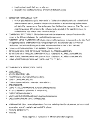

The document outlines key thermal relationships and physical properties for tubular heat exchangers. It discusses the overall heat transfer coefficient calculation and factors that influence fouling resistance like fluid properties and heat exchanger geometry. It also covers fluid temperature relationships, including logarithmic mean temperature difference and corrections for multipass flow. Physical properties covered include density, specific heat, thermal conductivity, and viscosity for various liquids and gases.


