Graybill-Hardison Final Poster
•
0 likes•70 views

- The document investigates how a vertical-downward elbow affects two-phase flow distribution compared to a vertical-upward elbow through CFD simulation and experimental data. - For two-phase flow through a vertical-downward elbow, the void fraction has a single peak along the inner wall that dissipates downstream, with little influence from secondary flow patterns. - This behavior is dramatically different than for a vertical-upward elbow and shows elbow-specific flow models are needed to capture these differences critical to reactor safety analysis.
Recommended

Recommended
More Related Content
What's hot
What's hot (20)
Similar to Graybill-Hardison Final Poster
Similar to Graybill-Hardison Final Poster (20)
Graybill-Hardison Final Poster
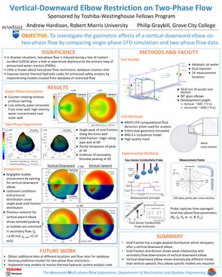
- 1. The Advanced Multi-phase Flow Laboratory, Department of Mechanical and Nuclear Engineering Vertical-Downward Elbow Restriction on Two-Phase Flow Sponsored by Toshiba-Westinghouse Fellows Program OBJECTIVE: To investigate the geometric effects of a vertical-downward elbow on two-phase flow by comparing single-phase CFD simulation and two-phase flow data. SIGNIFICANCE SUMMARY • Void fraction has a single-peaked distribution which dissipates after a vertical-downward elbow. • Void fraction distribution shows weak relationship with secondary flow downstream of vertical-downward elbow • Vertical-downward elbow shows dramatically different trends than vertical-upward; thus elbow-specific models are required RESULTS METHODS AND FACILITY FUTURE WORK • Obtain additional data at different locations and flow rates for database • Develop predictive models for two-phase flow restrictions • Implement new models to reactor thermal-hydraulic system analysis code • In disaster situations, two-phase flow is induced during a loss of coolant accident (LOCA) when a leak or pipe break depressurize the primary loop of pressurized water reactors (PWRs). • Little is known about two-phase flow restrictions; database creation vital • Improve reactor thermal-hydraulic codes for enhanced safety analysis by implementing models created from database of restricted flow Single-Phase Simulation ● Counter-rotating vortices produce swirling ● Low velocity water emanates from inner wall; high velocity water concentrated near outer wall. Two-Phase Experiment ● Single peak of void fraction along the inner wall. ● Void fraction ‘ridge’ along pipe wall at 0D ● Partial dissipation of peak at 3D ● Evidence of secondary bimodal peaking at 3D ● Negligible bubble entrainment by swirling for vertical-downward elbow. ● Upstream conditions and pressure distribution cause single-peak void fraction distribution ● Previous research for vertical-pward elbow shows bimodal peaking as bubbles are entrained in secondary flow. (jf =3.00 m/s; jg, atm =0.14 m/s) Comparison Test Facility CFD Methods Experimental Methods ● ANSYS CFX computational fluid dynamics solver used for analysis ● Entire loop geometry simulated ● RNG k-ε turbulence model ● High quality mesh ● 50.8 mm ID acrylic test section ● 90° glass elbows ● Development Length: ○ Vertical: ~60D (~3 m) ○ Horizontal: ~180D (~9 m) Four-Sensor Conductivity Probe Measurement principle Kim et al., 2014 120 data points per cross-section Andrew Hardison, Robert Morris University Philip Graybill, Grove City College Mesh cross-section Probe captures time-averaged local two-phase flow parameters (Nb, fb, Vb, α, ai, & Dsm) Four-Sensor Conductivity Probe Schematic ● Adiabatic air-water ● Dual injection ● 24 measurement locations Measurement PointsVolumetric liquid flux (jf ) : 4.00 m/s Volumetric gas flux (jg, atm ) : 0.23 m/s L=3DL=0D Bulk velocity (Ubulk ) : 4.00 m/s Void Fraction L=0D L=3D Previous Work Vertical-UpwardVertical-Downward L=3D L=0D Previous Work (Yadav, 2013)