Atac brochure-cloud point analyser
•
0 likes•99 views

The Cloud Point test cell is first flushed through with a fresh sample. A small amount of sample is then isolated in the cell and allowed to settle for a predetermined period to allow any air bubbles or solids to separate. The sample cell is then cooled at a controlled rate by a Peltier cooler with excess heat being removed by a coolant. An optical detector senses when the sample is starting to become cloudy as waxy components start to precipitate. The temperature at which this occurs is taken as the cloud point

Recommended
Recommended
More Related Content
What's hot
What's hot (20)
Similar to Atac brochure-cloud point analyser
Similar to Atac brochure-cloud point analyser (20)
More from European Tech Serv
More from European Tech Serv (20)
Recently uploaded
Recently uploaded (20)
Atac brochure-cloud point analyser
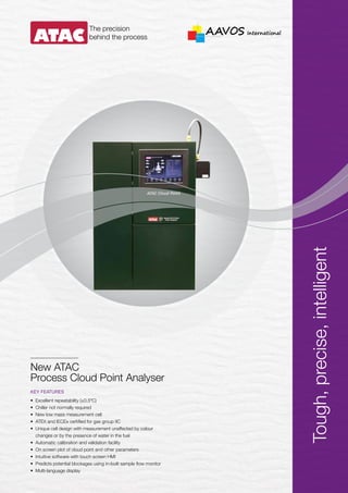
- 1. KEY FEATURES • Excellent repeatability (±0.5ºC) • Chiller not normally required • New low mass measurement cell • ATEX and IECEx certified for gas group IIC • Unique cell design with measurement unaffected by colour changes or by the presence of water in the fuel • Automatic calibration and validation facility • On screen plot of cloud point and other parameters • Intuitive software with touch screen HMI • Predicts potential blockages using in-built sample flow monitor • Multi-language display The precision behind the process New ATAC Process Cloud Point Analyser Tough,precise,intelligent
- 2. The ATAC Cloud Point is a completely automatic on line process stream analyser for measuring cloud point. The analysis results may be directly correlated to those obtained by the ASTM D2500 / D5773 / IP219 / EN23015 standard test methods. Principle of Operation The Cloud Point test cell is first flushed through with a fresh sample. A small amount of sample is then isolated in the cell and allowed to settle for a predetermined period to allow any air bubbles or solids to separate. The sample cell is then cooled at a controlled rate by a Peltier cooler with excess heat being removed by a coolant. An optical detector senses when the sample is starting to become cloudy as waxy components start to precipitate. The temperature at which this occurs is taken as the cloud point. Typical Applications • Diesel and biodiesel product blending • Middle distillate monitoring • Heating oil specification Features New Ultra High performance measuring cell The ATAC Cloud Point analyser uses a light source and detector mounted at right angles to each other. This arrangement offers enhanced signal to noise ratio compared to conventional in line source and detector arrangements. The new cell also features a brand new patented measuring cell; with unique “Smart Amplification” signal processing the new cell is able to detect cloud point in even the most challenging of samples including coloured, domestic, marine and motor fuels and biodiesel without the need for any adjustments to analyser settings. High sensitivity combined with ultimate reliability The new optical cell uses an LED light source to increase lamp life by 10x and boro-silicate light guides prevent contamination by the sample. The plug and play configuration of the new cell makes maintenance a breeze, the installation of a heater and higher powered peltier cooling further enhance cell performance and durability. ATEX certified controller with touch screen HMI The Cloud Point uses a hazardous area certified industrial PC, running Windows XP Professional, with an integral armoured glass touch screen interface as the main control element, thus avoiding the use of keyboards and pointing devices in hazardous areas. The use of an integrated PC with touch screen and modular serial I/O means that the controller electronics are realised with the minimum of components. On screen plotting of cloud point and other parameters The Cloud Point, cell temperature and detector signal results are available plotted on screen on a real time rolling basis allowing the user to scroll back over the last seven days.
- 3. Touch screen icons Edit parameters Real time & historical data The analyser control software is designed for ease of use and organised as a series of menu screens accessed and navigated by touching screen icons. The main screen features an animated mimic diagram of the analyser and other screens are available for setting up the analyser and plotting real time and historical data. Touching any configurable parameter on a menu screen opens a help box which will describe what the parameter does and what values it can have. An on screen keyboard will also appear. Language options are English, French, Italian, Spanish, Mandarin and Russian. Other languages will be available on request. Intuitive User Friendly Software User configurable analogue outputs The Cloud Point isolated analogue current output ranges are now fully programmable by the user. Offsets may be introduced so the analyser can agree with laboratory results. Choice of cloud point detection methods The Cloud Point provides the user with a choice of two cloud point detection methods. The first method allows the user to set a threshold detector value to trigger cloud point detection. The second method allows the user to set a rate of change of the detector signal to trigger cloud point detection. Automatic calibration and validation The Cloud Point can carry out single point automatic calibration or validation on demand or on a timed basis. The user may define the allowable deviation permitted for the validation or calibration to be deemed successful. These deviations are displayed on a control chart so that the user can detect any underlying trends that may result in analyser failure. Comprehensive programmable alarms The Cloud Point continually monitors operating parameters and advises the user of any fault conditions that arise. The analyser provides two levels of alarm conditions. The user can configure many of the actual alarm level settings and all alarm conditions may be user assigned to be either active or inactive and fatal or warning. The analyser provides volt free changeover contacts to notify warning. In-built sample flow meter The Cloud Point has a built-in positive displacement flow meter, fitted as standard, that accurately monitors and displays sample flow rate. The flow alarm settings may be user assigned. The flow monitor is sensitive enough to detect small flows associated with leaking valves and also detects blockages caused by wax deposits. A heating cycle can be programmed for clearing any wax. Multiple analysis methods Once the Cloud Point has been set-up and configured, all the parameters are stored in a method table. It has the ability to store up to eight method tables and these may be allocated to individual sample streams and be named, called up and used as required. This is particularly useful if the user has summer and winter grades requiring a remote switchover. User configurable cooling rates The rates at which the Cloud Point cools the sample may be configured by the user. The threshold points for switching between one cooling rate and another may also be user configurable. NeSSI compatible sample system The Cloud Point is compatible with NeSSI sample system components and has space to house all necessary components as well as calibration valves. The I/O is able to monitor all necessary temperatures, pressures and flows.
- 4. ATAC is a subsidiary of Advanced Holdings Ltd. (Advanced), a leading specialist provider of engineering services, equipment and environmental technologies to the global Energy industry for over 20 years. Advanced has established a global presence in Asia, the Middle East, Europe and USA and is listed on the Mainboard of the Singapore Stock Exchange. ATAC-CLOUDPOINT-001-R0-EN-APR-2014 SPECIFICATIONS Measuring range: -42 to +30ºC (user configurable). Repeatability: ±0.5ºC Cycle time: 4-8 minutes typical. Analogue output: 4 off 4-20mA fully isolated. Maximum load impedance 700 ohms. Serial output: Modbus RTU over RS485 as standard. All alarms, remote calibration and remote standby are available over Modbus. Full remote operation over LAN, Ethernet hardwired or via fibre optic cable are available as an option. Other protocols are available on request. Alarm contacts: 2 sets of C/O voltage free alarm contacts rated 0.5A at 250VAC and 1A at 24VDC are provided to notify common warning or fatal alarms. Contact inputs: The Cloud Point can monitor 4 off customer external contacts (minimum rating 24V 0.1A). These may be named by the customer and allocated into the warning or fatal alarm groups as required. STANDARD CONNECTIONS Sample: Process and calibration ¼” API female. Drain and vent: ¼” API female. Signal and power: M20 Mounting: Free standing as standard. Wall mount frame option available. SAMPLE CONDITIONS Pressure: 0.5-2.5 barg Temperature: At least 14ºC above the expected/last cloud point (user configurable). Maximum 60ºC. Sample temperature is continually monitored and sample is isolated if its temperature is too high. Flow during normal operation: 20-60 I/hr free of dissolved water and entrained solids. Sample flow through analyser cell is continually monitored. Flow during calibration: Typically 1-2 litres per calibration cycle. Sample disposal: The analyser sample outlet must be connected to an atmospheric drain or sample recovery unit. Analyser vent: The analyser vapour vent must be connected to atmosphere. UTILITY REQUIREMENTS Power supply: 100-240VAC 50/60Hz maximum load, 500VA (auto sensing). Instrument air: Between 4-10 barg, dew point less than -20ºC, flow 100 I/min Coolant flow: Typically 30 I/hr at a pressure of 5 barg maximum. Coolant temperature: Depends upon cloud point. Typically a 50ºC differential should exist between coolant temperature and lowest measurable cloud point. Coolant may be water, chilled glycol and water mix or the sample itself. Coolant temperature is continually monitored. CONTROL UNIT Processor: Pentium M 1.6 GHz Internal memory: 1024 MB Hard disk: 60 GB HD Ethernet: 10/100Mbit EEx-e Interfaces: 1 x USB EEx-e, 4 x USB EEx-i, 1 x RS232 EEx-i, 1 x RS485 EEx-e Analogue input/output resolution: 16 bits ENVIRONMENTAL REQUIREMENTS Operating temperature range: -5 to +50ºC Overall ingress protection: IP55 (front screen IP66) Relative humidity: 10-95% (non condensing) Hazardous area certification: The Cloud Point is suitable for Zone 1 (Div 1) areas, and is certified to ATEX II 2(1) G Ex d px [ia] [p] IIC T4 and also IECEx Ex d px [ia] [p] IIC T4 Gb. Equivalent to Class 1 Div 1 Groups A, B, C & D. HMI Intrinsically safe TFT touch screen display, integral to control unit, with a 15.1" screen and glass front with an anti-reflective chemical coating. XGA resolution (1024 x 768 pixel). Multi-language capability. CALIBRATION/VALIDATION Calibration/validation is carried out automatically on demand or on a timed basis. Block and bleed isolation valves are provided for the calibration/validation standards. During calibration the analyser valves are arranged to dead end the standard sample minimising its use. Contacts notify calibration/validation in progress and validation pass or fail. Your partner in process analyses More than 20 years of experience AAVOS International bvba Sparkevaardekenstraat 3 B-8600 Diksmuide - Belgium www.aavos.be info@aavos.be T. +32 (0)51 69 78 15 F. +32 (0)51 69 78 17