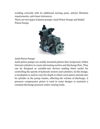
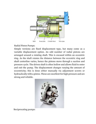
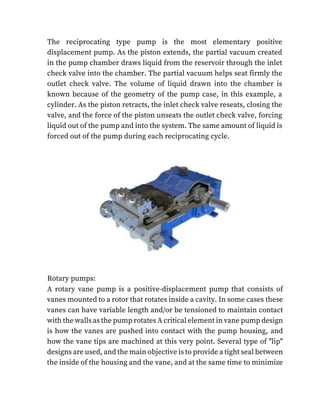
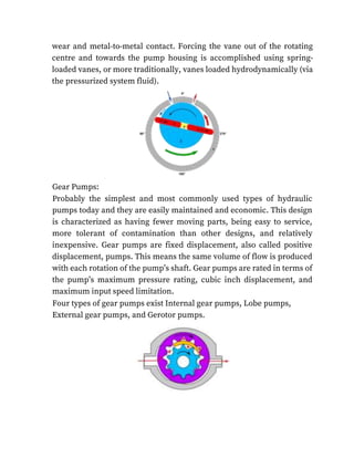
1. Dr . D. Y. PATIL, PRATISHTAN’S
Y.B.PATIL POLYTECHNIC
SECTOR NO. 29, AKURDI, PUNE-411044, INDIA
DR. D.Y.PATIL PRATHISHTAN’S
CERTIFICATE
DEVENDRA SUTHAR ( Y- 2077)
YOGESH YELAVI ( Y-2083)
AVINASH SAKHARE( Y-2058)
HRISHIKESH TARANGE ( Y-2070)
PRATHAMESH ROKDA ( Y-2031)
ATHARVA PATIL ( Y-2075)
This is to certify that , has satisfactorily carried out and complete the project work entitled,
Types of pumps for selection of types of pumps:
This work is being submitted for the Award of Diploma in Civil Engineering Partial Fulfilment Of
Prescribed Syllabus Of M.S.B.T.E Mumbai For Academic Year 2020-21.
Mrs. Pushpa Bhambare Mr. A.H. PATIL GUIDE HOD
Prof. A.S.KONDEKAR
PRINCIPAL
Micro-Project Proposal
Types of pumps for selection of types of pumps
1. Aims/Benefits of the Micro-Project : To get the knowledge about types of pumps and its
uses , its use in civil engineering.
2. 2. Course Outcomes Addressed
1. Got to learn about Hydraulics
2. Got to learn about its types & its uses .
3. Got to learn about its types and different types of pumps
3 . Proposed Methodology
Firstly, we have learned about Hydraulics what it’s actually means from book. Then,
collected the information from different reference books and internet. Collected the pictures
of various types of pumps in hydraulics
Made a project on Microsoft word on the Hydraulics and pasted some pictures of the
same.
4.Action Plan
Sr .N
o.
Details of activity Planned
Start Date
Planned
finish date
Name of
responsible Team
Member
1) Collection of information 03/05/2021 04/05/2021 DEVENDRA
SUTHAR YOGESH
YELAVI
2) Working on Microsoft word 03/05/2021 04/05/2021 AVINASH SAKHARE
HRISHIKESH TARANGE
3) Taking prints of the
project made in
Microsoft word Binding
it.
04/05/2021 06/05/2021 PRATHAMESH
ROKDA ATHARVA
PATIL
5.Resources Required
Sr.no
.
Name of
Resources/materials
Specifications Qty
.
remarks
1. Internet and reference books Collect information 1
2. laptop Working on Microsoft word 1
3. Name of Team Members
DEVENDRA SUTHAR ( Y- 2077)
YOGESH YELAVI ( Y-2083)
AVINASH SAKHARE( Y-2058)
HRISHIKESH TARANGE ( Y-2070)
PRATHAMESH ROKDA ( Y-2031)
ATHARVA PATIL ( Y-2075)
Micro Project Evaluation sheet
Name of Students - Enrollment No: DEVENDRA SUTHAR ( Y- 2077)
1901340104 YOGESH YELAVI ( Y-2083) 1901340103 AVINASH SAKHARE( Y-
2058) 1901340080 HRISHIKESH TARANGE ( Y-2070) 1901340102
PRATHAMESH ROKDA ( Y-2031) 1901340080 ATHARVA PATIL ( Y-2075)
1901340081
Name of Programme : CIVIL ENGINEERING
Semester :4th
Course Title : CIVIL ENGINEERING
Subject Name: Hydraulics
4. Title of Micro-Project: Different types of pumps
Course Outcomes Achieved:
Got to learn about Types of pumps
Got to learn about its component and uses.
Got to learn about their types and pumps and where its uses
NAME ROLL
NO.
(A)
PROCESS AND
PRODUCT RELATED
MARKS (6 MARKS)
(B)
INDIVIDUAL
PRESENTATION
/VIVA (4MARKS)
TOTAL
MARKS
(10
MARKS)
DEVENDRA
SUTHAR
(Y-2077)
YOGESH YELAVI ( Y-2083)
AVINASH
SAKHARE
( Y-2058)
HRISHIKESH
TARANGE
( Y-2070)
PRATHAMESH
ROKDA
( Y-2031)
ATHARVA PATIL ( Y-2075)
Comments/ Suggestions about team work/leadership/inter-personal communication ( if any)
Name and designation of the
teacher Dated Signature
Hydraulic pumps:
Hydraulic pumps are sources of power for many dynamic machines.
Hydraulic pumps are capable of pushing large amounts of oil through
hydraulic cylinders or hydraulic motors. In this fashion, the pump
converts the mechanical energy of the drive (i.e. torque, speed) into
5. hydrostatic energy (i.e. flow, pressure). You can use hydraulic machines
- equipped with a pump - to do different types of work such as lift, lower,
open, close or rotate components. Hydraulic pumps operate according
to the displacement principle. This involves the existence of
mechanically sealed chambers in the pump. Through these chambers,
fluid is transported from the inlet (suction port) of the pump to the outlet
(pressure port). The sealed chambers ensure that there is no direct
connection between the two ports of the pump. As a result, these pumps
are very suitable to operate at high system pressures and are ideal for
hydraulics.
Where hydraulic pumps are used:
Hydraulic pumps are used on excavators, cranes, loaders, tractors,
vacuum trucks, forestry equipment, graders, dump trucks, mining
machinery, etc. Mobile applications use hydraulic pumps more
prolifically than do industrial machines, because electric actuators are
generally not used for mobile machinery.
Classification of pumps:
vane pumps:
a number of vanes slide in slots in a rotor which rotates in a housing or
ring. The housing may be eccentric with the center of the rotor, or its
shape may be oval, Figure 5. In some designs, centrifugal force holds the
vanes in contact with the housing, while the vanes are forced in and out
of the slots by the eccentricity of the housing. In one vane pump, light
springs hold the vanes against the housing; in
another pump design, pressurized pins urge the vanes outward. During
rotation, as the space or chamber enclosed by vanes, rotor, and housing
increases, a vacuum is created, and atmospheric pressure forces oil into
6. this space, which is the inlet side of the pump. As the space or volume
enclosed reduces, the liquid is forced out through the discharge ports.
All pumps may be classified as either positive-displacement or non-
positive-displacement. Most pumps used in hydraulic systems are
positive-displacement.
non-positive-displacement pump produces a continuous flow. However,
because it does not provide a positive internal seal against slippage, its
output varies considerably as pressure varies. Centrifugal and propeller
pumps are examples of non-positive displacement pumps. If the output
port of a non-positive displacement pump were blocked off, the pressure
would rise, and output would decrease to zero. Although the pumping
element would continue moving, flow would stop because of slippage
inside the pump. Different types of hydraulic pumps are used in a wide
scope of engineering fields and are available in a variety of designs. Each
type has a different internal mechanism based on the same fundamental
principles. So let us introduce some of the common types.
Piston Pumps:
When high operating pressures are required, these hydraulic pump
types are often used. Piston pumps will traditionally withstand higher
pressures than gear pumps with comparable displacements; however,
there is a higher initial cost associated
with piston pumps as well as a lower resistance to contamination and
increased complexity. This complexity falls to the equipment designer
and service technician to understand to ensure the piston pump is
7. working correctly with its additional moving parts, stricter filtration
requirements, and closer tolerances.
There are two types of piston pumps: Axial Piston Pumps and Radial
Piston Pumps
Axial Piston Pumps:
Axial piston pumps use axially mounted pistons that reciprocate within
internal cylinders to create alternating suction and discharge flow. They
can be designed as variable-rate devices making them useful for
controlling the speeds of hydraulic motors and cylinders. In this design,
a swashplate is used to vary the depth to which each piston extends into
its cylinder as the pump rotates, affecting the volume of discharge. A
pressure compensator piston is used in some designs to maintain a
constant discharge pressure under varying loads.
8. Radial Piston Pumps:
Simple versions are fixed displacement type, but many come as a
variable displacement option. An odd number of radial pistons are
arranged around a rotating shaft. This is encased within an eccentric
ring. As the shaft rotates the distance between the eccentric ring and
shaft centerline varies, hence the pistons move through a suction and
pressure cycle. The driven shaft is often hollow and allows fluid to enter
and exit the pump. The displacement changes varying the amount of
eccentricity; this is done either manually via adjustment screws or
hydraulically with a piston. These are excellent for high pressure and are
strong and reliable.
Reciprocating pumps:
9. The reciprocating type pump is the most elementary positive
displacement pump. As the piston extends, the partial vacuum created
in the pump chamber draws liquid from the reservoir through the inlet
check valve into the chamber. The partial vacuum helps seat firmly the
outlet check valve. The volume of liquid drawn into the chamber is
known because of the geometry of the pump case, in this example, a
cylinder. As the piston retracts, the inlet check valve reseats, closing the
valve, and the force of the piston unseats the outlet check valve, forcing
liquid out of the pump and into the system. The same amount of liquid is
forced out of the pump during each reciprocating cycle.
Rotary pumps:
A rotary vane pump is a positive-displacement pump that consists of
vanes mounted to a rotor that rotates inside a cavity. In some cases these
vanes can have variable length and/or be tensioned to maintain contact
with the walls as the pump rotates A critical element in vane pump design
is how the vanes are pushed into contact with the pump housing, and
how the vane tips are machined at this very point. Several type of "lip"
designs are used, and the main objective is to provide a tight seal between
the inside of the housing and the vane, and at the same time to minimize
10. wear and metal-to-metal contact. Forcing the vane out of the rotating
centre and towards the pump housing is accomplished using spring-
loaded vanes, or more traditionally, vanes loaded hydrodynamically (via
the pressurized system fluid).
Gear Pumps:
Probably the simplest and most commonly used types of hydraulic
pumps today and they are easily maintained and economic. This design
is characterized as having fewer moving parts, being easy to service,
more tolerant of contamination than other designs, and relatively
inexpensive. Gear pumps are fixed displacement, also called positive
displacement, pumps. This means the same volume of flow is produced
with each rotation of the pump’s shaft. Gear pumps are rated in terms of
the pump’s maximum pressure rating, cubic inch displacement, and
maximum input speed limitation.
Four types of gear pumps exist Internal gear pumps, Lobe pumps,
External gear pumps, and Gerotor pumps.
11. Lobe pumps:
Lobe pumps work on a similar principle of working like that of external
gear pumps. However, in Lobe pumps, the lobes do not
make any contact like the external gear pump. Lobe contact is prevented
by external timing gears located in the gearbox. Similar to the external
gear pump, the lobes rotate to create expanding volume at the inlet. Now,
the fluid flows into the cavity and is trapped by the lobes. Fluid travels
around the interior of the casing in the pockets between the lobes and
the casing. Finally, the meshing of the lobes forces the liquid to pass
through the outlet port. The bearings are placed out of the pumped
liquid. Therefore the pressure is limited by the bearing location and shaft
deflection.
Lobe pumps are frequently used in food applications because they
handle solids without damaging the product. Large-sized particles can
be pumped much more effectively than in other positive displacement
types. As the lobes do not make any direct contact 9 therefore, the
clearance is not as close as in other Positive displacement pumps. This
specific design of the pump makes it suitable to handle low viscosity
fluids with diminished performance.
Internal Gear Pumps:
The internal gear pump uses the meshing action of an internal and
external gear combined with a crescent-shaped sector element to create
12. fluid flow. The axis of the external gear is offset from that of the internal
gear. As the two gears rotate, their coming out of and into mesh creates
suction and discharge zones. The sector serves as
a barrier between suction and discharge. Another internal gear pump,
the Gerotor, uses meshing trochoidal gears to achieve the same suction
and discharge zones without needing a sector element.
External Gear Pumps:
External Gear pumps rely on the counter-rotating motion of meshed
external spur gears to impart motion to a fluid. They are generally fixed-
displacement designs, very simple and robust. They are commonly
found as close-coupled designs where the motor and pump share a
common shaft and mounting.
Oil travels around the periphery of the pump housing between the teeth
of the gears. On the outlet side, the meshing action of the teeth decreases
the volume to discharge the oil. The small amount of oil that is trapped
between the re-meshing gears discharges through the Elkins and back to
the pump’s suction side. External gear pumps are very popular in fixed-
displacement hydraulic applications as they are capable of providing
very high pressures.
13. Gerotor pumps:
Gerotor is a positive displacement pump. The name Gerotor is derived
from “Generated Rotor”. At the most basic level, a Gerotor is essentially
one that is moved via fluid power. Originally this fluid
was water, today the wider use is in hydraulic devices. A Gerotor pump
is an internal gear pump without the crescent. The important
advantages of these pumps are high-speed operation, constant
discharge in all pressure conditions, bidirectional operation, less sound
in running condition, and less maintenance due to only two moving
parts and one stuffing box, etc. However, the pump is having some
limitations such as medium pressure operating range, clearance is
fixed, solids can’t be pumped, and overhung load on the shaft bearing,
etc.
Screw pumps:
Screw pumps (fixed displacement) consist of two Archimedes' screws
that intermesh and are enclosed within the same chamber. These pumps
are used for high flows at relatively low pressure (max 100 bars (10,000
kPa)). They were used on board ships where a constant pressure
hydraulic system extended through the whole ship, especially to control
ball valves[clarification needed]
but also to help drive the steering gear and other
systems. The advantage of the screw pumps is the low sound level of
these pumps; however, the efficiency is not high.
14. The major problem of screw pumps is that the hydraulic reaction force
is transmitted in a direction that's axially opposed to the direction of the
flow.
Thank
You