The ASTM A105/A105M specification outlines the requirements for forged carbon steel piping components used in pressure systems, including flanges, fittings, and valves, applicable for ambient and elevated temperatures. It specifies manufacturing criteria, chemical and mechanical properties, and dimensions, along with compliance to referenced standards. Supplementary requirements for testing and inspection may be included at the purchaser's request, and the specification is relevant for U.S. Department of Defense use.
![Designation: A105/A105M − 18 Endorsed by
Manufacturers Standardization Society
of the Valve and Fittings Industry
Used in USDOE-NE Standards
Standard Specification for
Carbon Steel Forgings for Piping Applications1
This standard is issued under the fixed designation A105/A105M; the number immediately following the designation indicates the year
of original adoption or, in the case of revision, the year of last revision. A number in parentheses indicates the year of last reapproval.
A superscript epsilon (´) indicates an editorial change since the last revision or reapproval.
This standard has been approved for use by agencies of the U.S. Department of Defense.
1. Scope*
1.1 This specification2
covers forged carbon steel piping
components for ambient- and higher-temperature service in
pressure systems. Included are flanges, fittings, valves, and
similar parts ordered either to dimensions specified by the
purchaser or to dimensional standards such as the MSS,
ASME, and API specifications referenced in Section 2. Forg-
ings made to this specification are limited to a maximum
weight of 10 000 lb [4540 kg]. Larger forgings may be ordered
to Specification A266/A266M. Tubesheets and hollow cylin-
drical forgings for pressure vessel shells are not included
within the scope of this specification. Although this specifica-
tion covers some piping components machined from rolled bar
and seamless tubular products (see 5.2), it does not cover raw
material produced in these product forms.
1.2 Supplementary requirements are provided for use when
additional testing or inspection is desired. These shall apply
only when specified individually by the purchaser in the order.
1.3 Specification A266/A266M covers other steel forgings
and Specifications A675/A675M and A696 cover other steel
bars.
1.4 This specification is expressed in both inch-pound units
and SI units. However, unless the order specifies the applicable
“M” specification designation (SI units), the material shall be
furnished to inch-pound units. The values stated in either SI
units or inch-pound units are to be regarded separately as
standard. Within the text, the SI units are shown in brackets.
The values stated in each system may not be exact equivalents;
therefore, each system shall be used independently of the other.
Combining values from the two systems may result in non-
conformance with the standard.
NOTE 1—The dimensionless designator NPS (nominal pipe size) has
been substituted in this standard for such traditional terms as “nominal
diameter,” “size,” and “nominal size.”
1.5 This international standard was developed in accor-
dance with internationally recognized principles on standard-
ization established in the Decision on Principles for the
Development of International Standards, Guides and Recom-
mendations issued by the World Trade Organization Technical
Barriers to Trade (TBT) Committee.
2. Referenced Documents
2.1 In addition to those reference documents listed in
Specification A961/A961M, the following list of standards
apply to this specification:
2.2 ASTM Standards:3
A266/A266M Specification for Carbon Steel Forgings for
Pressure Vessel Components
A675/A675M Specification for Steel Bars, Carbon, Hot-
Wrought, Special Quality, Mechanical Properties
A696 Specification for Steel Bars, Carbon, Hot-Wrought or
Cold-Finished, Special Quality, for Pressure Piping Com-
ponents
A788/A788M Specification for Steel Forgings, General Re-
quirements
A961/A961M Specification for Common Requirements for
Steel Flanges, Forged Fittings, Valves, and Parts for
Piping Applications
2.3 MSS Standards:
SP 44 Standard for Steel Pipe Line Flanges4
1
This specification is under the jurisdiction of ASTM Committee A01 on Steel,
Stainless Steel and Related Alloys and is the direct responsibility of Subcommittee
A01.22 on Steel Forgings and Wrought Fittings for Piping Applications and Bolting
Materials for Piping and Special Purpose Applications.
Current edition approved Sept. 1, 2018. Published September 2018. Originally
approved in 1926. Last previous edition approved in 2014 as A105/A105M – 14.
DOI: 10.1520/A0105_A0105M-18.
2
For ASME Boiler and Pressure Vessel Code applications see related Specifi-
cation SA-105 in Section II of that Code.
3
For referenced ASTM standards, visit the ASTM website, or contact ASTM
Customer Service. For Annual Book of ASTMStandards volume information, refer
to the standard’s Document Summary page onthe ASTMwebsite.
4
Available from Manufacturers Standardization Society of the Valve and Fittings
Industry (MSS), 127 Park St., NE, Vienna, VA 22180-4602.
*A Summary of Changes section appears at the end of this standard
Copyright © ASTM International, 100 Barr Harbor Drive, PO Box C700, West Conshohocken, PA 19428-2959. United States
This international standard was developed in accordance with internationally recognized principles on standardization established in the Decision on Principles for the
Development of International Standards, Guides and Recommendations issued by the World Trade Organization Technical Barriers to Trade (TBT) Committee.
1
Ferrous & Nonferrous Flange Supplier: Shijiazhuang Metalsin Pipeline Tech Co. Ltd
Website: www.pipingpipeline.com | Standard Specification: ASTM A105
w
w
w
.pipingpipeline.com
For Internal Communication Only](https://image.slidesharecdn.com/astma105-190823053648/85/ASTM-A105-material-standard-1-320.jpg)
![Designation: A105/A105M − 18 Endorsed by
Manufacturers Standardization Society
of the Valve and Fittings Industry
Used in USDOE-NE Standards
Standard Specification for
Carbon Steel Forgings for Piping Applications1
This standard is issued under the fixed designation A105/A105M; the number immediately following the designation indicates the year
of original adoption or, in the case of revision, the year of last revision. A number in parentheses indicates the year of last reapproval.
A superscript epsilon (´) indicates an editorial change since the last revision or reapproval.
This standard has been approved for use by agencies of the U.S. Department of Defense.
1. Scope*
1.1 This specification2
covers forged carbon steel piping
components for ambient- and higher-temperature service in
pressure systems. Included are flanges, fittings, valves, and
similar parts ordered either to dimensions specified by the
purchaser or to dimensional standards such as the MSS,
ASME, and API specifications referenced in Section 2. Forg-
ings made to this specification are limited to a maximum
weight of 10 000 lb [4540 kg]. Larger forgings may be ordered
to Specification A266/A266M. Tubesheets and hollow cylin-
drical forgings for pressure vessel shells are not included
within the scope of this specification. Although this specifica-
tion covers some piping components machined from rolled bar
and seamless tubular products (see 5.2), it does not cover raw
material produced in these product forms.
1.2 Supplementary requirements are provided for use when
additional testing or inspection is desired. These shall apply
only when specified individually by the purchaser in the order.
1.3 Specification A266/A266M covers other steel forgings
and Specifications A675/A675M and A696 cover other steel
bars.
1.4 This specification is expressed in both inch-pound units
and SI units. However, unless the order specifies the applicable
“M” specification designation (SI units), the material shall be
furnished to inch-pound units. The values stated in either SI
units or inch-pound units are to be regarded separately as
standard. Within the text, the SI units are shown in brackets.
The values stated in each system may not be exact equivalents;
therefore, each system shall be used independently of the other.
Combining values from the two systems may result in non-
conformance with the standard.
NOTE 1—The dimensionless designator NPS (nominal pipe size) has
been substituted in this standard for such traditional terms as “nominal
diameter,” “size,” and “nominal size.”
1.5 This international standard was developed in accor-
dance with internationally recognized principles on standard-
ization established in the Decision on Principles for the
Development of International Standards, Guides and Recom-
mendations issued by the World Trade Organization Technical
Barriers to Trade (TBT) Committee.
2. Referenced Documents
2.1 In addition to those reference documents listed in
Specification A961/A961M, the following list of standards
apply to this specification:
2.2 ASTM Standards:3
A266/A266M Specification for Carbon Steel Forgings for
Pressure Vessel Components
A675/A675M Specification for Steel Bars, Carbon, Hot-
Wrought, Special Quality, Mechanical Properties
A696 Specification for Steel Bars, Carbon, Hot-Wrought or
Cold-Finished, Special Quality, for Pressure Piping Com-
ponents
A788/A788M Specification for Steel Forgings, General Re-
quirements
A961/A961M Specification for Common Requirements for
Steel Flanges, Forged Fittings, Valves, and Parts for
Piping Applications
2.3 MSS Standards:
SP 44 Standard for Steel Pipe Line Flanges4
1
This specification is under the jurisdiction of ASTM Committee A01 on Steel,
Stainless Steel and Related Alloys and is the direct responsibility of Subcommittee
A01.22 on Steel Forgings and Wrought Fittings for Piping Applications and Bolting
Materials for Piping and Special Purpose Applications.
Current edition approved Sept. 1, 2018. Published September 2018. Originally
approved in 1926. Last previous edition approved in 2014 as A105/A105M – 14.
DOI: 10.1520/A0105_A0105M-18.
2
For ASME Boiler and Pressure Vessel Code applications see related Specifi-
cation SA-105 in Section II of that Code.
3
For referenced ASTM standards, visit the ASTM website, or contact ASTM
Customer Service. For Annual Book of ASTMStandards volume information, refer
to the standard’s Document Summary page onthe ASTMwebsite.
4
Available from Manufacturers Standardization Society of the Valve and Fittings
Industry (MSS), 127 Park St., NE, Vienna, VA 22180-4602.
*A Summary of Changes section appears at the end of this standard
Copyright © ASTM International, 100 Barr Harbor Drive, PO Box C700, West Conshohocken, PA 19428-2959. United States
This international standard was developed in accordance with internationally recognized principles on standardization established in the Decision on Principles for the
Development of International Standards, Guides and Recommendations issued by the World Trade Organization Technical Barriers to Trade (TBT) Committee.
1
Ferrous & Nonferrous Flange Supplier: Shijiazhuang Metalsin Pipeline Tech Co. Ltd
Website: www.pipingpipeline.com | Standard Specification: ASTM A105
w
w
w
.pipingpipeline.com
For Internal Communication Only](https://image.slidesharecdn.com/astma105-190823053648/75/ASTM-A105-material-standard-1-2048.jpg)
![8.3 Tension Tests:
8.3.1 One tension test shall be made for each heat of
as-forged components.
8.3.2 One tension test shall be made from each heat-treating
charge. If more than one heat is included in such a charge, each
heat shall be tested.
8.3.2.1 When forgings of different shapes are included in the
same heat-treating charge, the test specimen shall be obtained
from the heaviest cross-section of the thickest forging, except
for hubbed flanges (see 8.3.3). The test specimen shall repre-
sent all forgings from the same heat and heat-treating charge
whose maximum thicknesses do not exceed the thickness of the
test forging.
8.3.2.2 When the heat-treating temperatures are the same
and the furnaces (either batch or continuous type), are con-
trolled within 625 °F [614 °C] and equipped with recording
pyrometers so that complete records of heat treatment are
available, then one tension test from each heat is required
instead of one test from each heat in each heat-treatment
charge. The test specimen material shall be included with a
furnace charge.
8.3.3 Testing shall be performed as specified in Specifica-
tion A961/A961M. The largest feasible round specimen shall
be used except when hollow cylindrically shaped parts are
machined from seamless tubulars. When hollow cylindrically
shaped parts are machined from seamless tubular materials,
strip tests may be used. The tension test specimen shall be
obtained from a production forging, or from an integral
prolongation representative of the hub location of a flange, or
the heaviest cross section of a fitting, valve, or other part within
the scope of this specification.
8.3.4 Forgings too small to permit obtaining a subsize
specimen of 0.250 in. [6.35 mm] diameter or larger parallel to
the dimension of maximum working, and produced in equip-
ment unsuitable for the production of a separately forged test
bar such as an automatic or semi-automatic press, may be
accepted on the basis of hardness only. One percent of the
forgings per lot, where a lot is the product from a heat, or, if
heat treated, the product of a heat per furnace charge, or ten
forgings, whichever is the lesser number, shall be selected at
random, prepared, and tested using the standard Brinell test.
The locations of the indentations shall be at the option of the
manufacturer but shall be selected to be representative of the
forging as a whole. One indentation per forging shall be
required but additional indentations may be made to establish
the representative hardness. The hardness of all forgings so
tested shall be 137 to 197 HBW inclusive.
8.4 Hardness Tests:
8.4.1 Two hardness tests shall be made for each heat of
as-forged components. When more than one forging is pro-
duced from each heat, a minimum of two forgings shall be
tested with one reading from each forging. When only one
forging is produced, it shall be tested in two locations.
8.4.2 Except when only one forging is produced, a mini-
mum of two forgings shall be hardness tested per batch or
continuous run as defined in 8.3.2.2 to ensure that forgings are
within the hardness limits given in Table 2. When only one
forging is produced, it shall be hardness tested in two locations
to ensure it is within the hardness limits given in Table 2.
8.4.3 Testing shall be as specified in Specification A961/
A961M. The purchaser may verify that the requirement has
been met by testing at any location on the forging, provided
such testing does not render the forging useless.
9. Hydrostatic Tests
9.1 Such tests shall be conducted by the forging manufac-
turer only when Supplementary Requirement S57 in Specifi-
cation A961/A961M is specified.
10. Retreatment
10.1 If the results of the mechanical tests do not conform to
the requirement specified, the manufacturer may heat treat or
reheat treat the forgings as applicable and repeat the test
specified in Section 8.
TABLE 2 Mechanical RequirementsA
Tensile strength, min, ksi [MPa] 70 [485]
Yield strength, min, ksi [MPa]B
36 [250]
Elongation in 2 in. or 50 mm, min, %:
Basic minimum elongation for walls 5⁄16 in. [7.9 mm]
and over in thickness, strip tests.
30
When standard round 2-in. or 50-mm gauge length or
smaller proportionally sized specimen with the gauge
length equal to 4D is used
22
For strip tests, a deduction for each 1⁄32 -in. [0.8-mm]
decrease in wall thickness below 5⁄16 in. [7.9 mm]
from the basic minimum elongation
of the percentage points of Table 3
1.50C
Reduction of area, min, %D
30
197Hardness, HBW, max
A
For small forgings, see 8.3.4.
B
Determined by either the 0.2 % offset method or the 0.5 % extension-under-load
method.
C
See Table 3 for computed minimum values.
D
For round specimens only.
TABLE 3 Computed Minimum Values
Wall Thickness Elongation in 2 in. or 50
mm, min, %mmin.
5⁄16 7.9(0.312) 30.00
9⁄32 7.1(0.281) 28.50
1⁄4 6.4(0.250) 27.00
7⁄32 5.6(0.219) 25.50
3⁄16 4.8(0.188) 24.00
5⁄32 4.0(0.156) 22.50
1⁄8 3.2(0.125) 21.00
3⁄32 2.4(0.094) 19.50
1⁄16 1.6(0.062) 18.00
Note—The above table gives the computed minimum elongation values for
each 1⁄32-in. [0.8-mm] decrease in wall thickness. Where the wall thickness lies
between two values shown above, the minimum elongation value is determined by
the following equation:
E 5 48T115.00
where:
E = elongation in 2 in. or 50 mm, %, and
T = actual thickness of specimen, in. [mm].
A105/A105M − 18
3
w
w
w
.pipingpipeline.com
Ferrous & Nonferrous Flange Supplier: Shijiazhuang Metalsin Pipeline Tech Co. Ltd
Website: www.pipingpipeline.com | Standard Specification: ASTM A105](https://image.slidesharecdn.com/astma105-190823053648/85/ASTM-A105-material-standard-3-320.jpg)
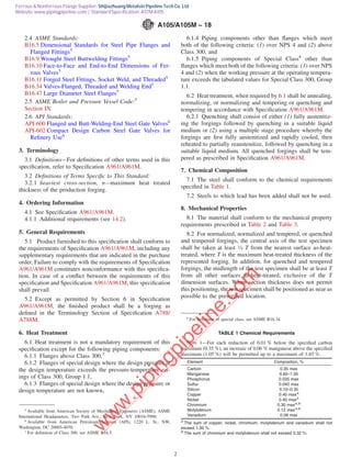
![11. Surface Finish, Appearance, and Corrosion
Protection
11.1 The requirements of Specification A961/A961M apply
to forgings and finished parts.
12. Repair by Welding
12.1 Repair of defects by the manufacturer is permissible
for forgings made to dimensional standards such as those of
ASME or for other parts made for stock by the manufacturer.
Prior approval of the purchaser is required to repair-weld
special forgings made to the purchaser’s requirements.
12.2 Weld repairs shall be made by a process that does not
produce undesirably high levels of hydrogen in the welded
areas.
12.3 All forgings repaired by welding shall be post-weld
heat treated between 1100 °F [593 °C] and the lower transfor-
mation temperature for a minimum of 1⁄2 h ⁄in. [1⁄2 h/25.4 mm]
of maximum section thickness, or alternatively annealed,
normalized and tempered, or quenched and tempered. If the
forging was not previously heat treated, the original tempering
temperature was exceeded, or the forging was fully heat treated
in the post weld cycle, then the forging shall be tested in
accordance with Section 8 on completion of the cycle.
12.4 The mechanical properties of the procedure-
qualification weldment shall, when tested in accordance with
Section IX of the ASME Boiler and Pressure Vessel Code,
conform with the requirements listed in Table 2 for the thermal
condition of repair-welded forgings.
13. Rejection and Rehearing
13.1 Each forging that develops injurious defects during
shop working or application shall be rejected and the manu-
facturer notified.
14. Certification
14.1 Identification Marking—For forgings made to specified
dimensions, when agreed upon by the purchaser, and for
forgings made to dimensional standards, application of identi-
fication marks as required in Specification A961/A961M shall
be the certification that the forgings have been furnished in
accordance with the requirements of this specification.
14.2 Test Reports—The manufacturer shall also provide the
following, where applicable:
14.2.1 Type heat treatment, Section 6,
14.2.2 Tensile property results, Section 8 (Table 2), report
the yield strength and tensile strength, in ksi [MPa], elongation
and reduction in area, in percent; and, if longitudinal strip
tension specimens are used, report the width of the gauge
length,
14.2.3 Chemical analysis results, Section 7 (Table 1), re-
ported results shall be to the same number of significant figures
as the limits specified in Table 1 for that element.
14.2.4 Hardness results, Section 8 (Table 2), a minimum of
two readings, and
14.2.5 Any supplementary testing required by the purchase
order.
15. Product Marking
15.1 In addition to marking requirements of Specification
A961/A961M, the following additional marking requirements
shall apply:
15.1.1 If the forgings have been quenched and tempered, the
letters “QT” shall be stamped on the forgings following this
specification number.
15.1.2 Forgings repaired by welding shall be marked with
the letter “W” following this specification number.
15.1.3 Plugs and bushings furnished to ASME B16.11
requirements are not required to be marked. Other parts
ordered with no marking are by agreement between the
purchaser and manufacturer.
15.1.4 When agreed upon between the purchaser and manu-
facturer and specified in the order, the markings shall be
painted or stenciled on the fitting or stamped on a metal or
plastic tag which shall be securely attached to the fitting.
15.2 Bar Coding—In addition to the requirements in
Specification A961/A961M, bar coding is acceptable as a
supplemental identification method. The purchaser may
specify in the order a specific bar coding system to be used.
The bar coding system, if applied at the discretion of the
supplier, should be consistent with one of the published
industry standards for bar coding. If used on small parts, the
bar code may be applied to the box or a substantially applied
tag.
16. Keywords
16.1 pipe fittings, steel; piping applications; pressure con-
taining parts; steel flanges; steel forgings, carbon; steel valves;
temperature service applications, elevated; temperature service
applications, high
A105/A105M − 18
4
w
w
w
.pipingpipeline.com
Ferrous & Nonferrous Flange Supplier: Shijiazhuang Metalsin Pipeline Tech Co. Ltd
Website: www.pipingpipeline.com | Standard Specification: ASTM A105](https://image.slidesharecdn.com/astma105-190823053648/85/ASTM-A105-material-standard-4-320.jpg)
![SUPPLEMENTARY REQUIREMENTS
The following supplementary requirements shall apply only when specified by the purchaser in the
inquiry, contract, and order.
S1. Hardness
S1.1 The purchaser may check the hardness of any or all
forgings supplied at any location on the forging and the
hardness shall be 137 to 197 HBW. All forgings not within the
specified hardness range shall be rejected.
S2. Heat Treatment
S2.1 All forgings shall be heat treated as specified by the
purchaser.
S2.2 When forgings not requiring heat treatment by 6.1 are
supplied heat treated by purchaser request, the basis for
determining conformance with Table 2 and Table 3 shall be
hardness testing per 8.4 and either (1) tensile testing of heat
treated forgings per 8.2, or (2) tensile tests from as-forged
forgings or separately forged test blanks, as agreed upon
between the supplier and purchaser.
S2.3 When test reports are required, and tensile test results
were obtained from as-forged forgings or as-forged test blanks,
it shall be so indicated on the test report.
S2.4 In addition to the marking required by Section 15, this
specification shall be followed by the letter: A for annealed, N
for normalized, NT for normalized and tempered, or QT for
quenched and tempered, as appropriate.
S3. Marking Small Forgings
S3.1 For small products where the space for marking is less
than 1 in. [25 mm] in any direction, test reports are mandatory
and marking may be restricted to only such symbols or codes
as are necessary to identify the parts with test reports.
S3.2 When the configuration or size does not permit mark-
ing directly on the forging, the marking method shall be a
matter of agreement between the manufacturer and the pur-
chaser.
S4. Carbon Equivalent
S4.1 The maximum carbon equivalent, based on heat
analysis, shall be 0.47 for forgings with a maximum section
thickness of 2 in. or less, and 0.48 for forgings with a
maximum section thickness of greater than 2 in.
S4.2 Determine the carbon equivalent (CE) as follows:
CE 5 C1Mn/61~Cr1Mo1V!/51~Ni1Cu!/15
S4.3 A lower maximum carbon equivalent may be agreed
upon between the supplier and the purchaser.
SUMMARY OF CHANGES
Committee A01 has identified the location of selected changes to this specification since the last issue,
A105/A105M–13, that may impact the use of this specification. (Approved Sept. 1, 2018)
(1) Revised Table 2, 8.3.4, and S1 hardness maximums.
ASTM International takes no position respecting the validity of any patent rights asserted in connection with any item mentioned
in this standard. Users of this standard are expressly advised that determination of the validity of any such patent rights, and the risk
of infringement of such rights, are entirely their own responsibility.
This standard is subject to revision at any time by the responsible technical committee and must be reviewed every five years and
if not revised, either reapproved or withdrawn. Your comments are invited either for revision of this standard or for additional standards
and should be addressed to ASTM International Headquarters. Your comments will receive careful consideration at a meeting of the
responsible technical committee, which you may attend. If you feel that your comments have not received a fair hearing you should
make your views known to the ASTM Committee on Standards, at the address shown below.
This standard is copyrighted by ASTM International, 100 Barr Harbor Drive, PO Box C700, West Conshohocken, PA 19428-2959,
United States. Individual reprints (single or multiple copies) of this standard may be obtained by contacting ASTM at the above
address or at 610-832-9585 (phone), 610-832-9555 (fax); or through the ASTM website.Permission rights to photocopy the
standard may also be secured from the Copyright Clearance Center, 222Rosewood Drive,Danvers, MA 01923, Tel: (978) 646-2600.
Contact the ASTM A105 flange manufacturer for more details: www.pipingpipeline.com
A105/A105M − 18
5
w
w
w
.pipingpipeline.com
Ferrous & Nonferrous Flange Supplier: Shijiazhuang Metalsin Pipeline Tech Co. Ltd
Website: www.pipingpipeline.com | Standard Specification: ASTM A105](https://image.slidesharecdn.com/astma105-190823053648/85/ASTM-A105-material-standard-5-320.jpg)