Download as PDF, PPTX

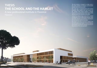
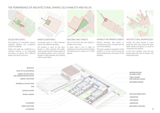
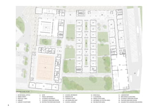


The document describes Enrico Manias's thesis project for a new professional institute in Florence, Italy. The project aims to harmoniously integrate the new building into the surrounding rural area through formal simplicity and an analysis of local architectural forms. The new institute consists of several blocks connected by an inner street and courtyards. It includes classrooms, laboratories, a library, gym, and public community spaces. The main facade is linear while the rear facade divides into pieces around courtyards to embrace the landscape.


