Download as PPSX, PPTX
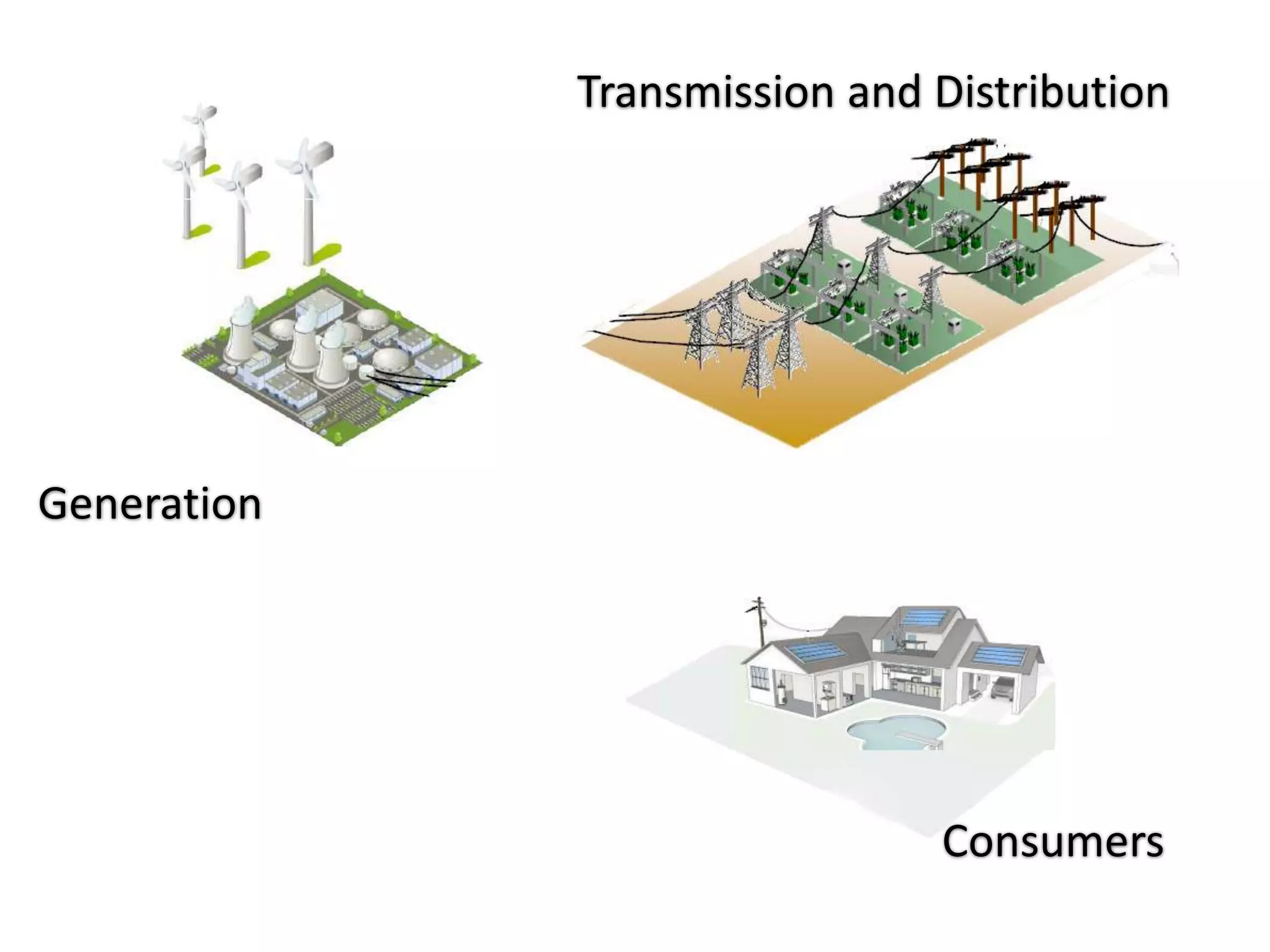
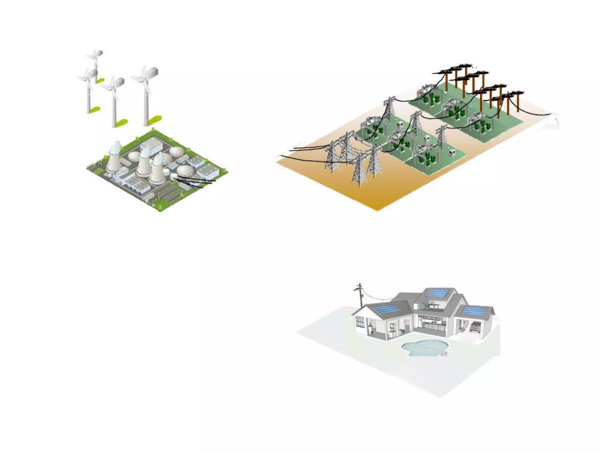
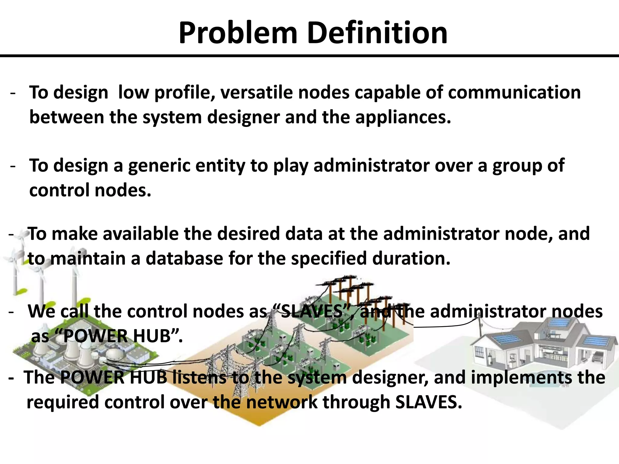
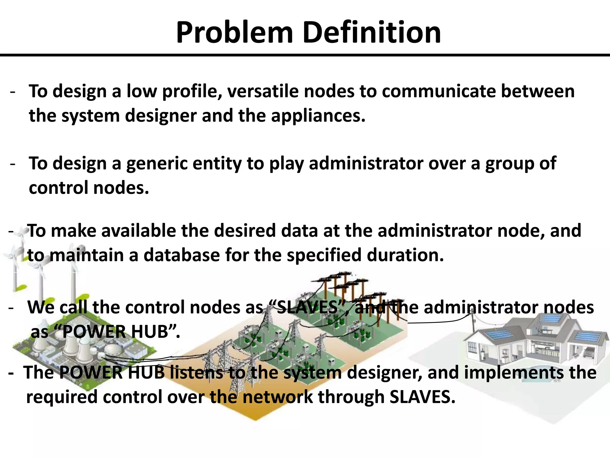
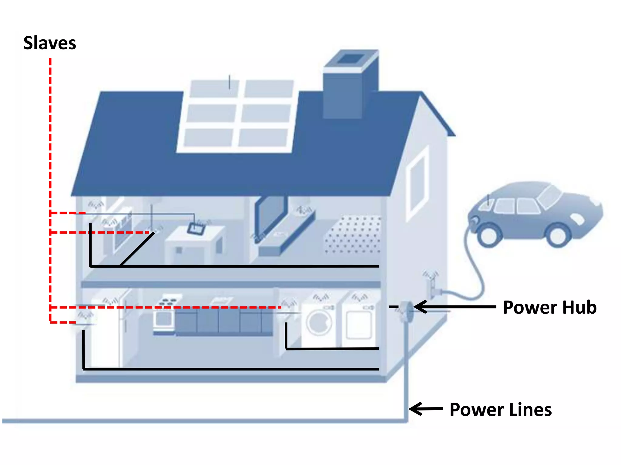
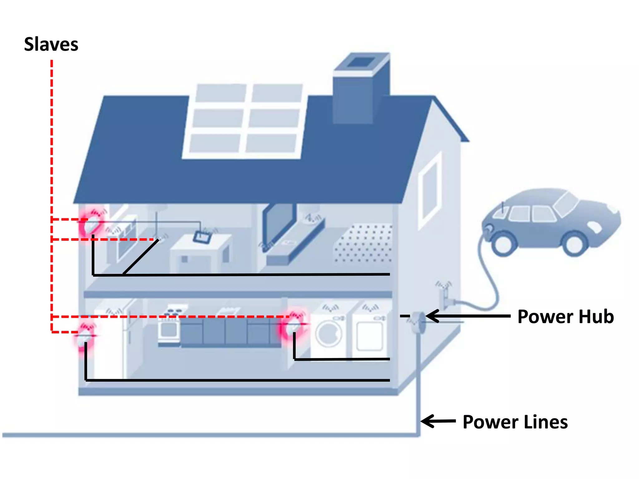


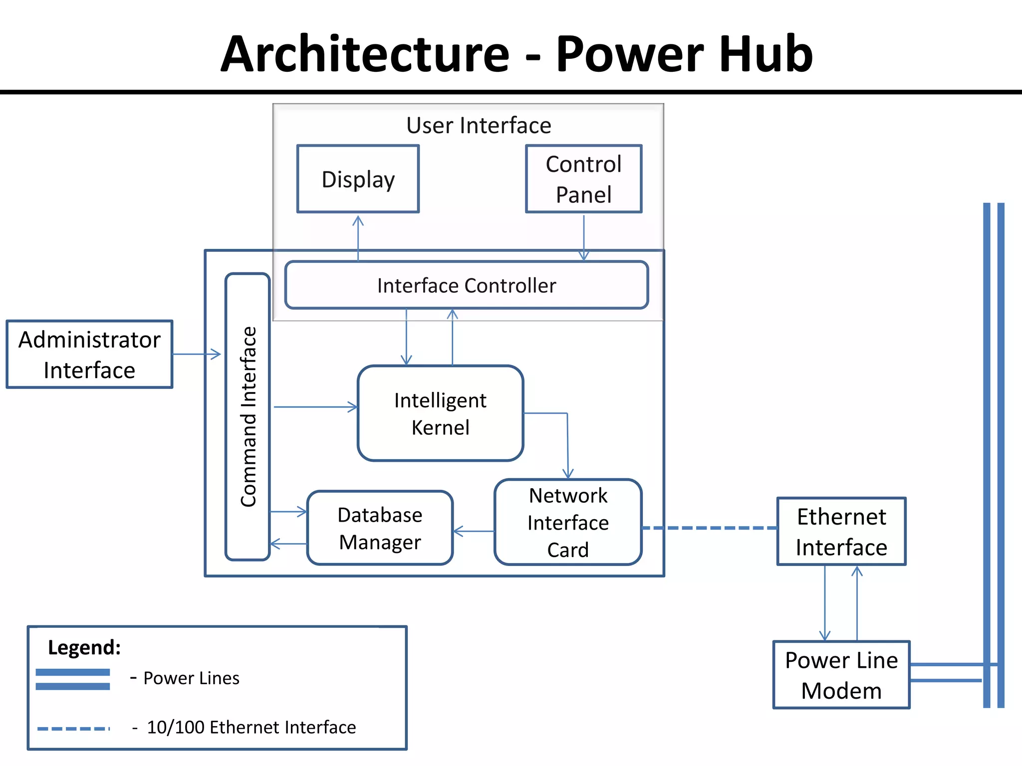

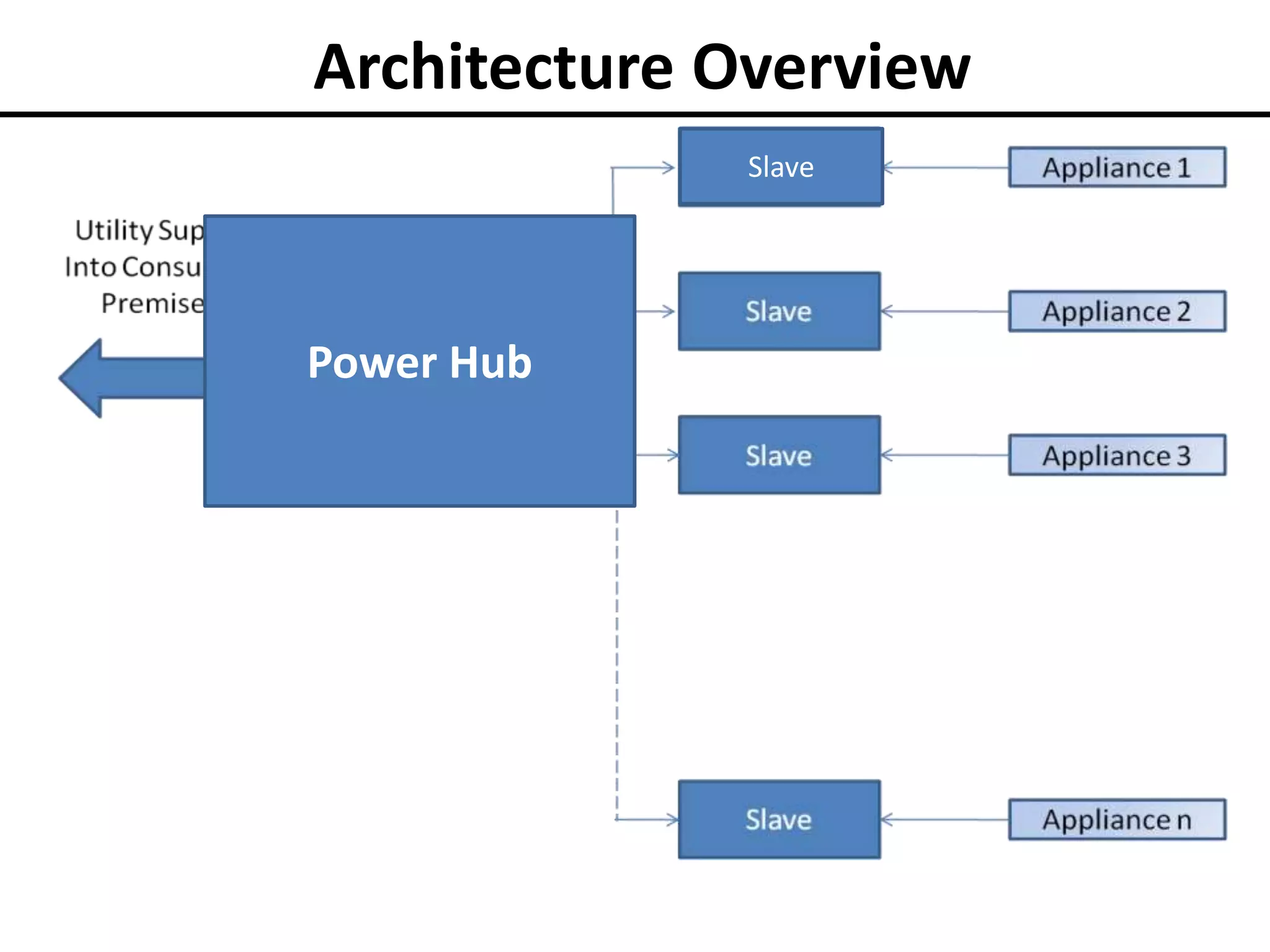
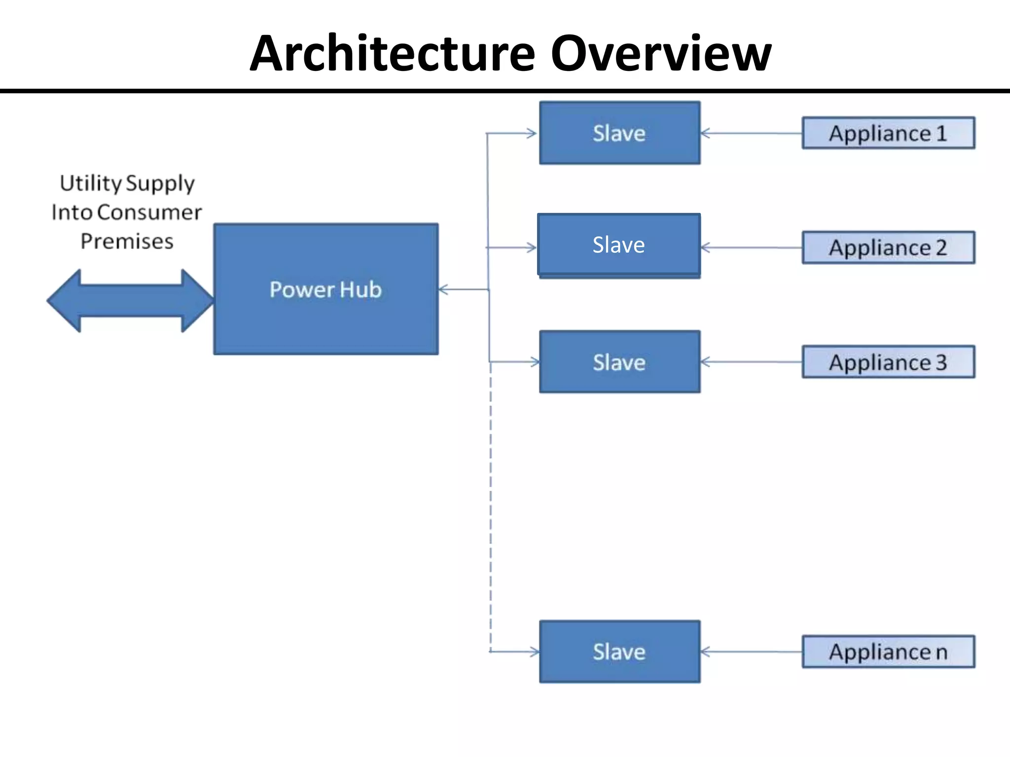


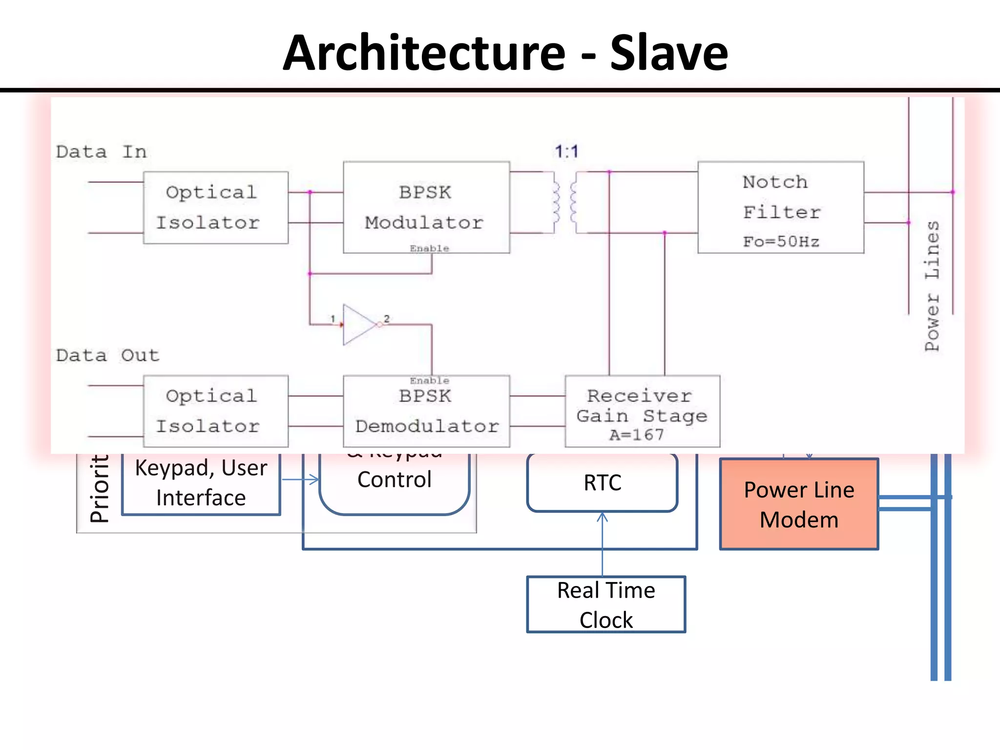
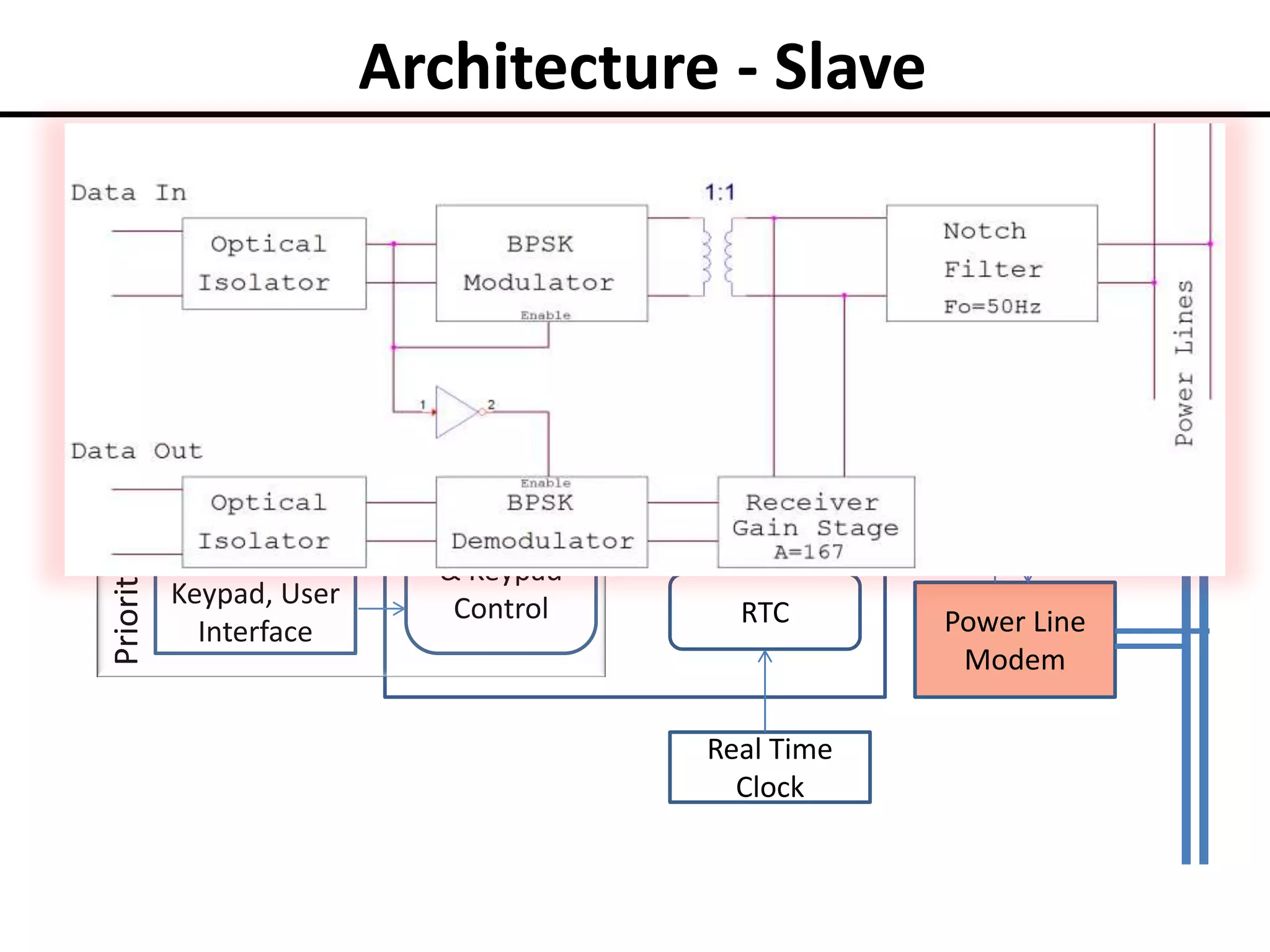
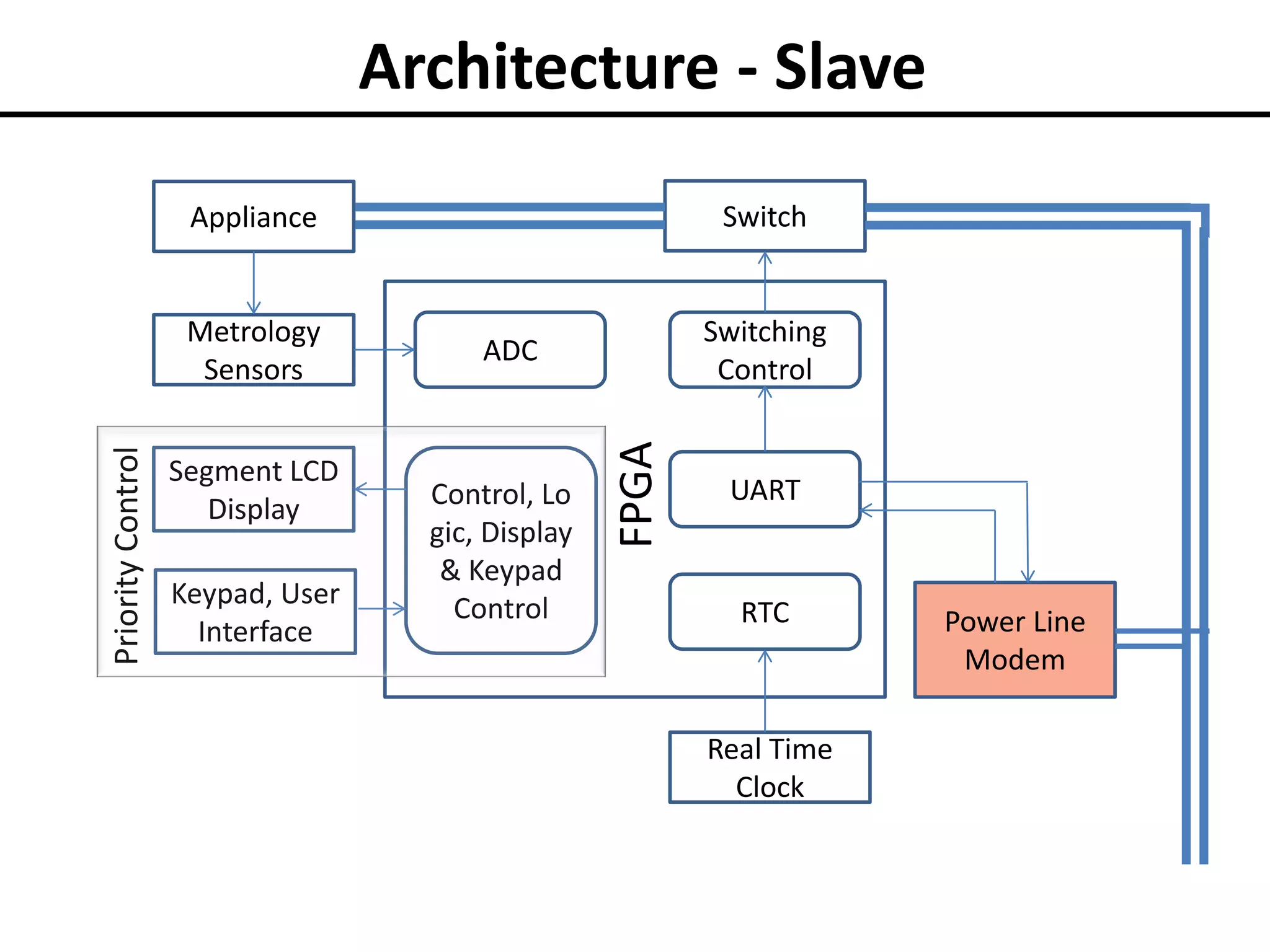


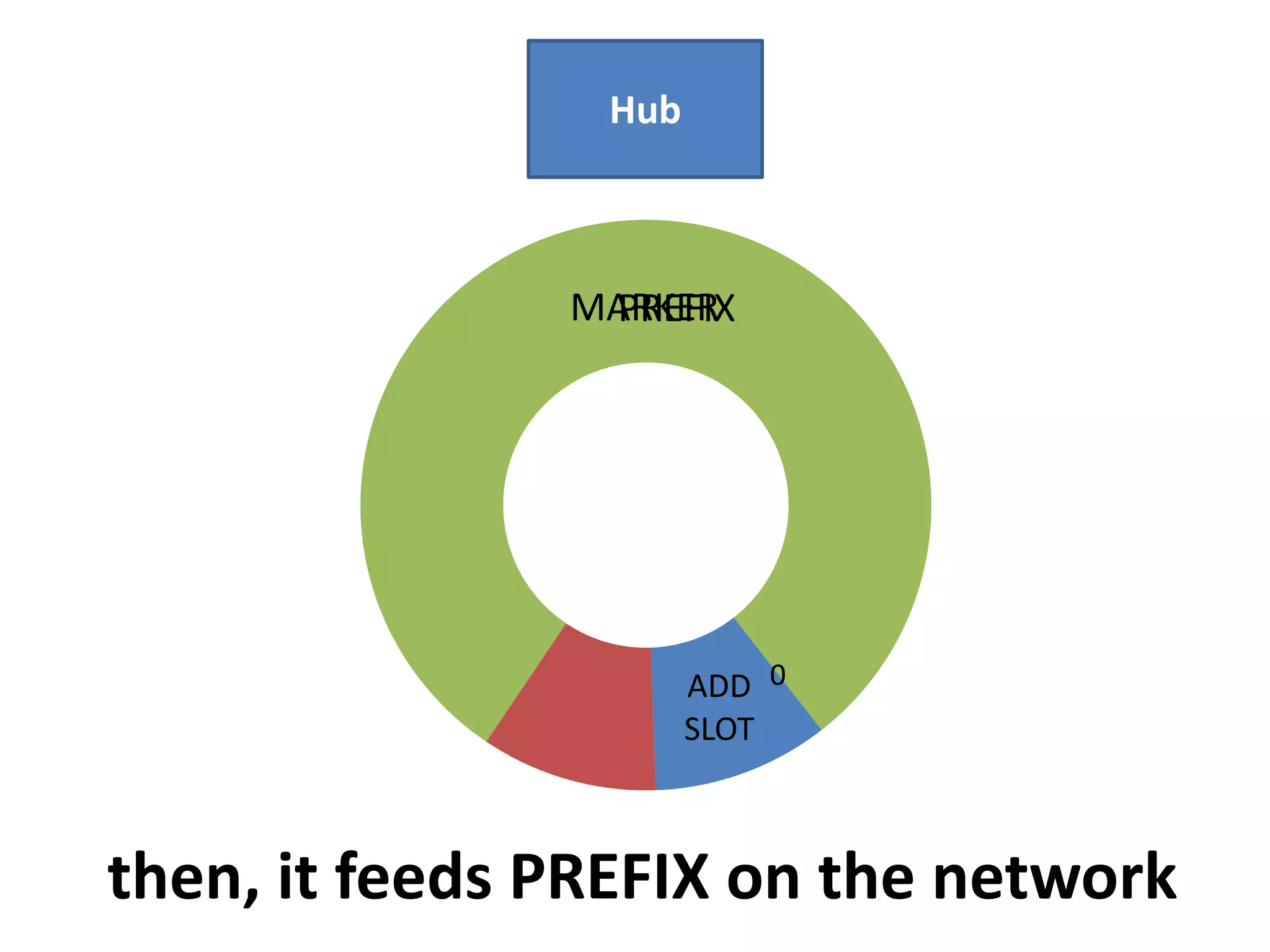
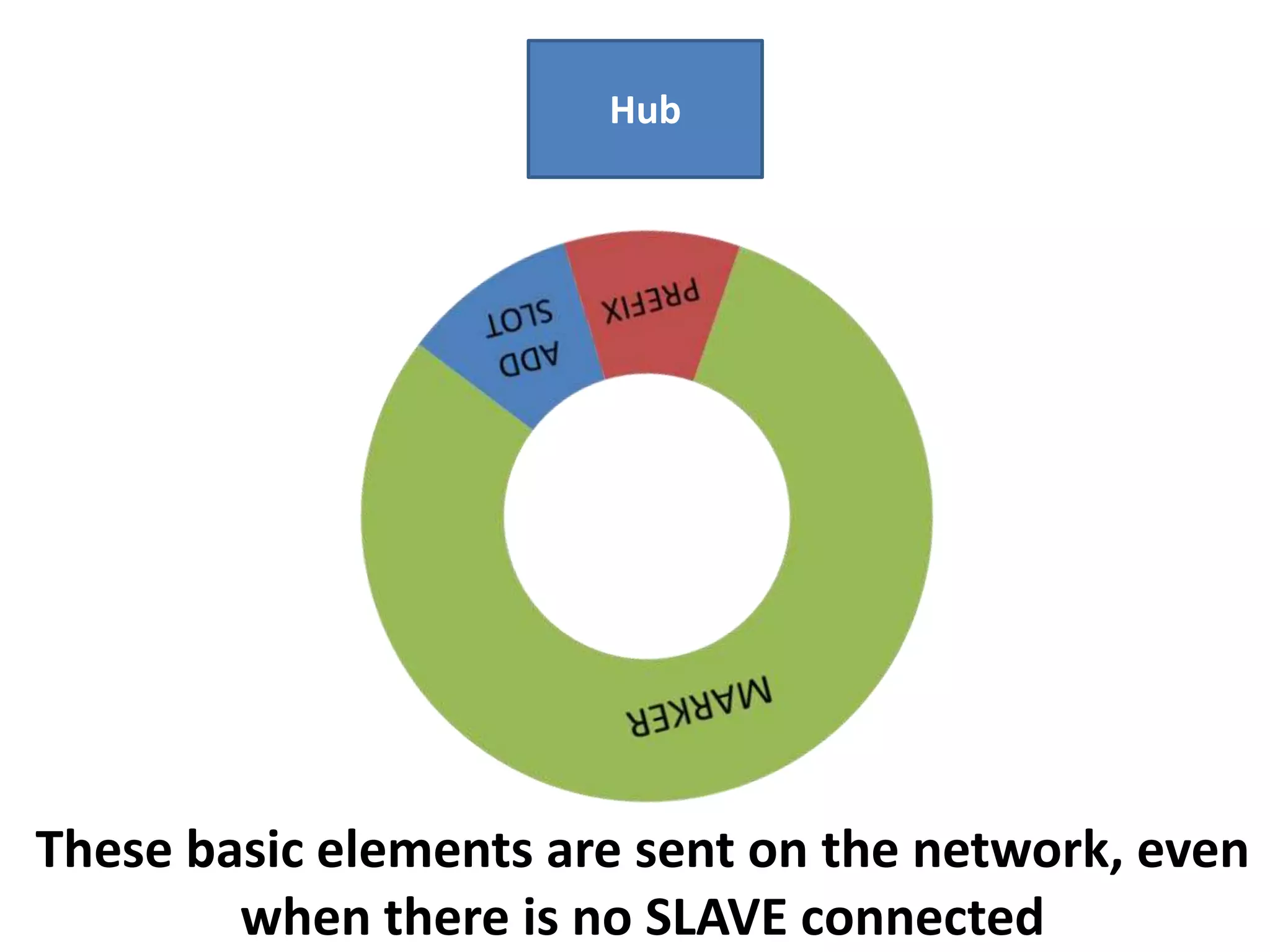
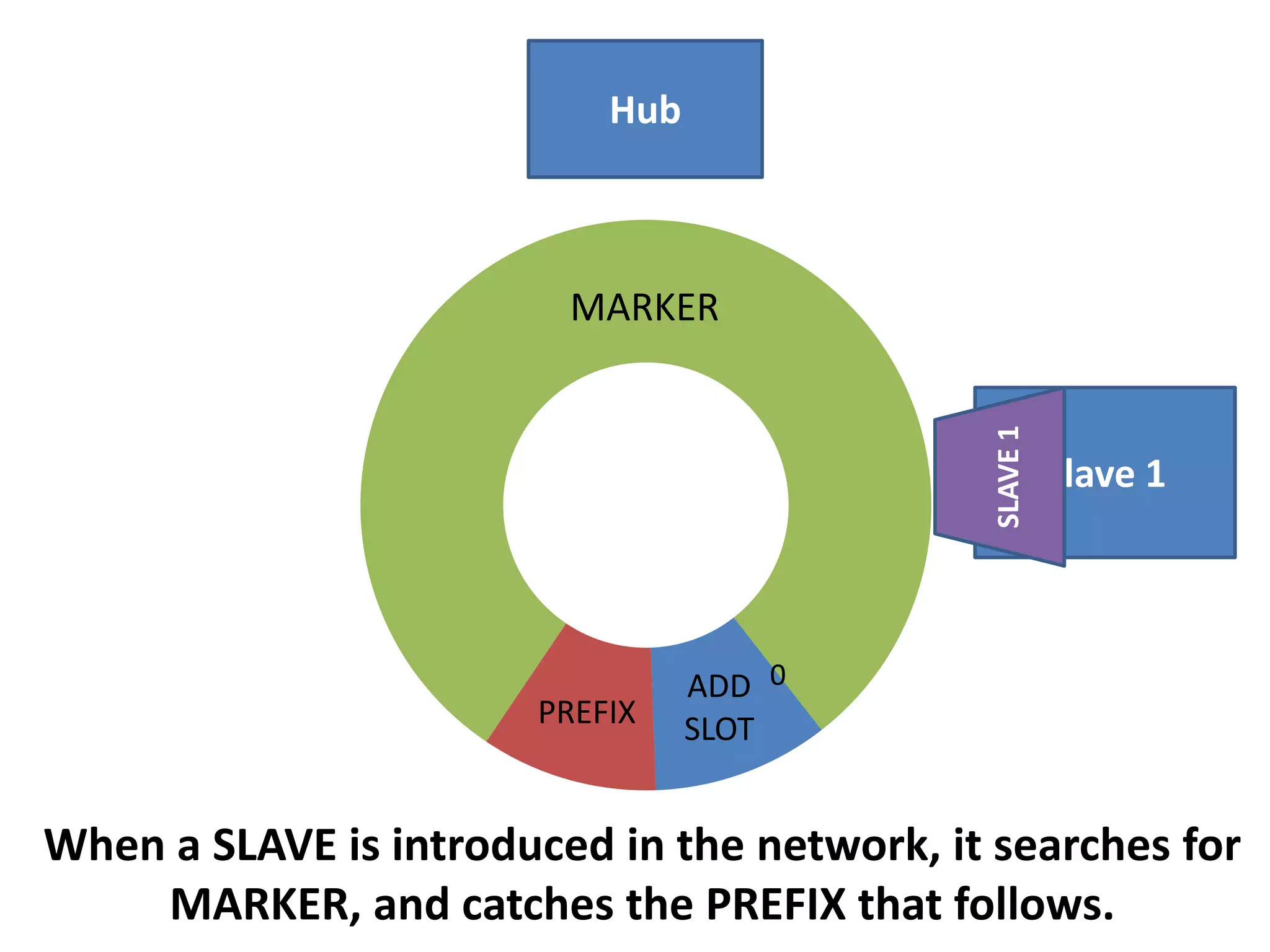
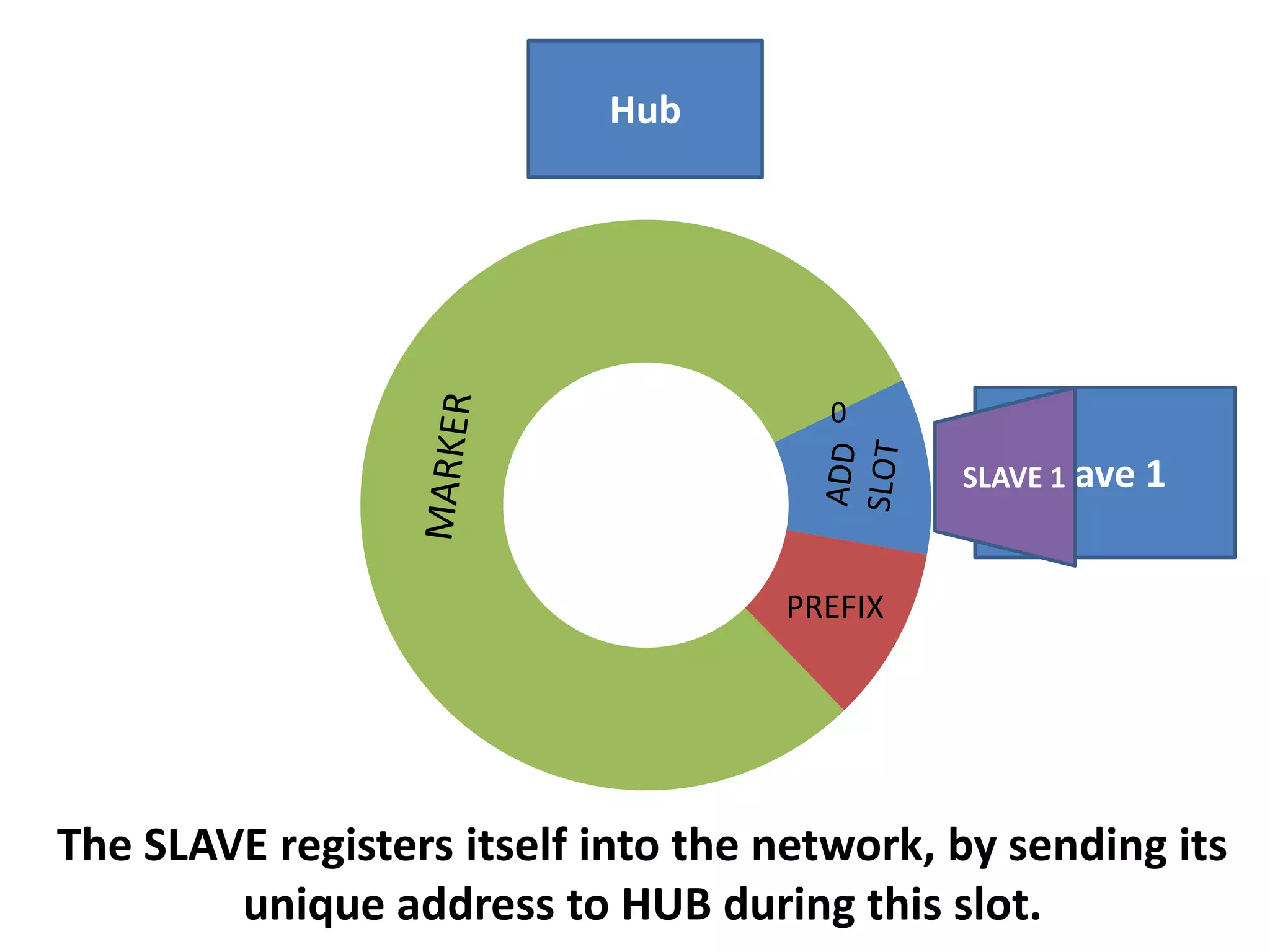
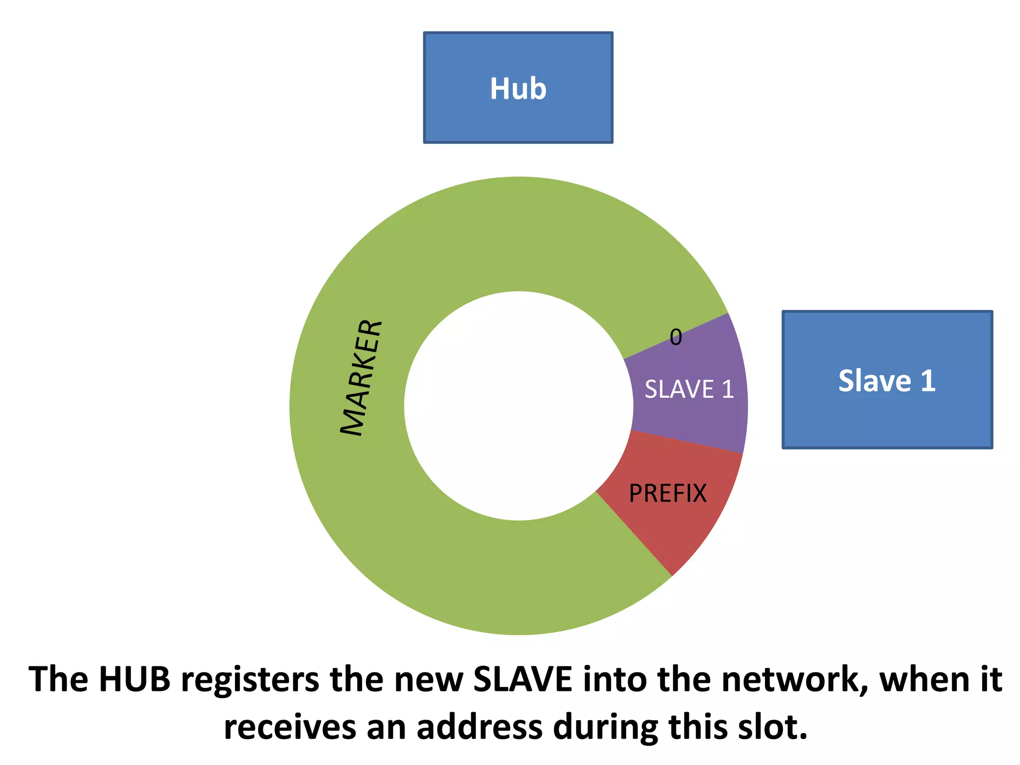
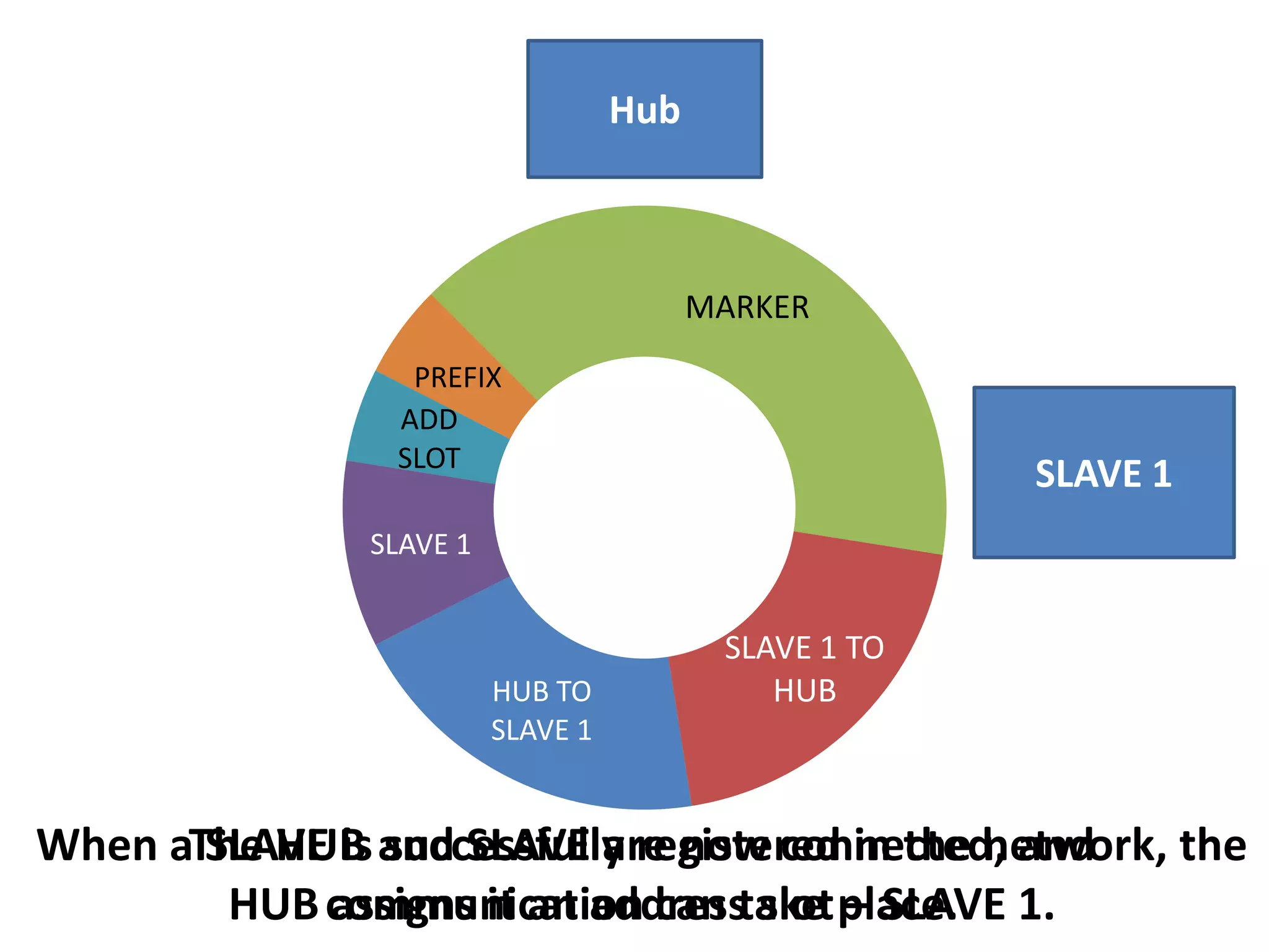
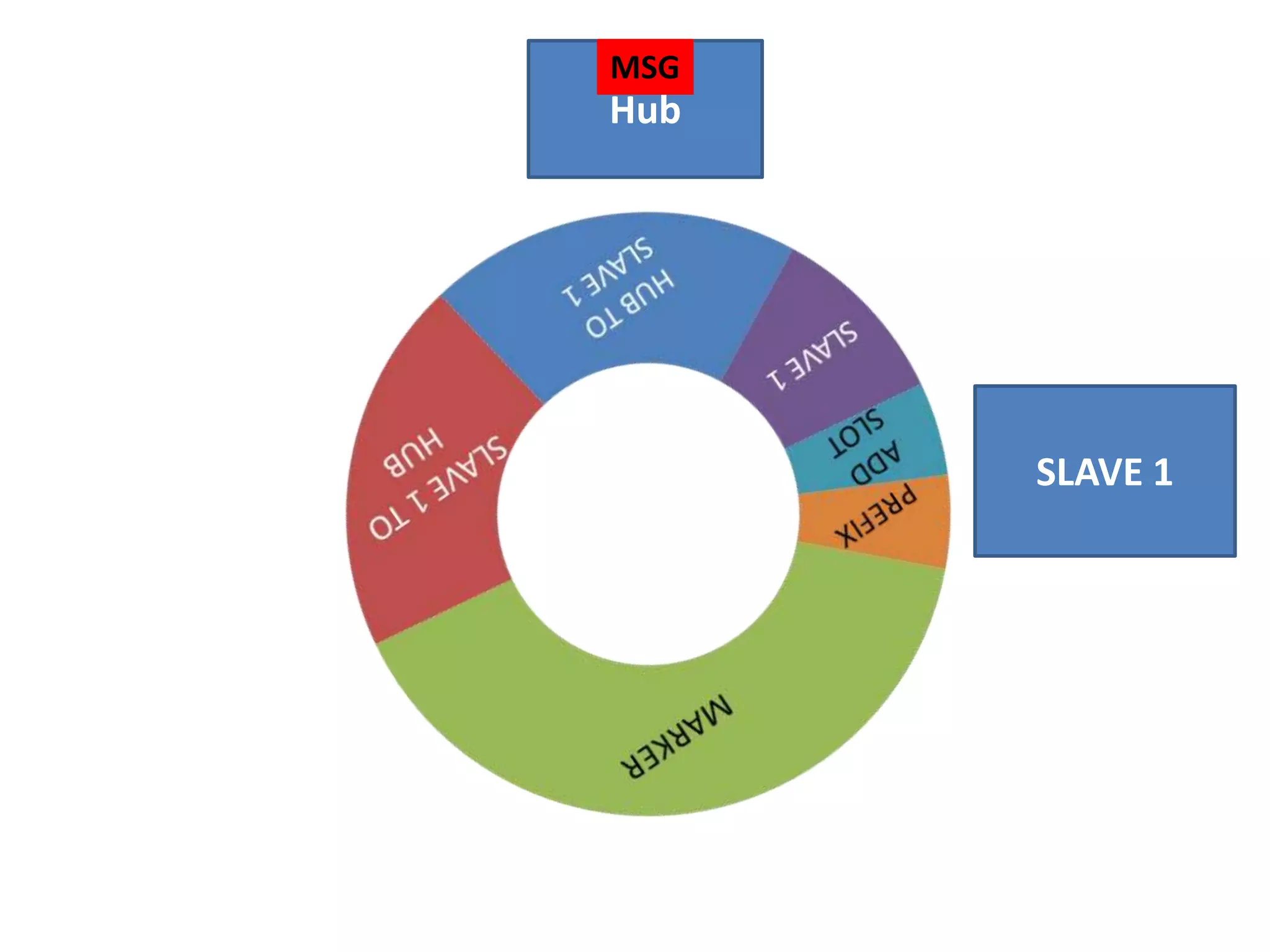
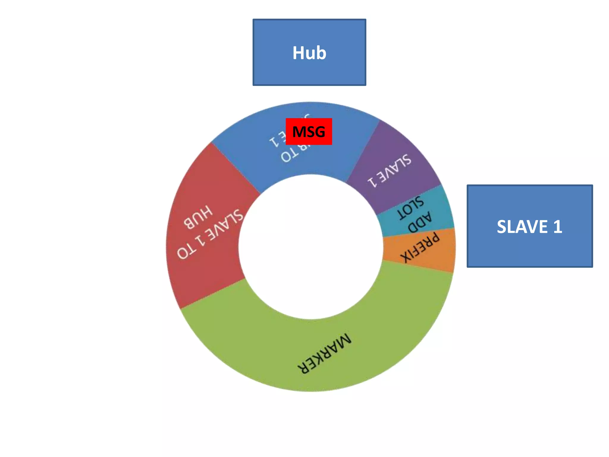
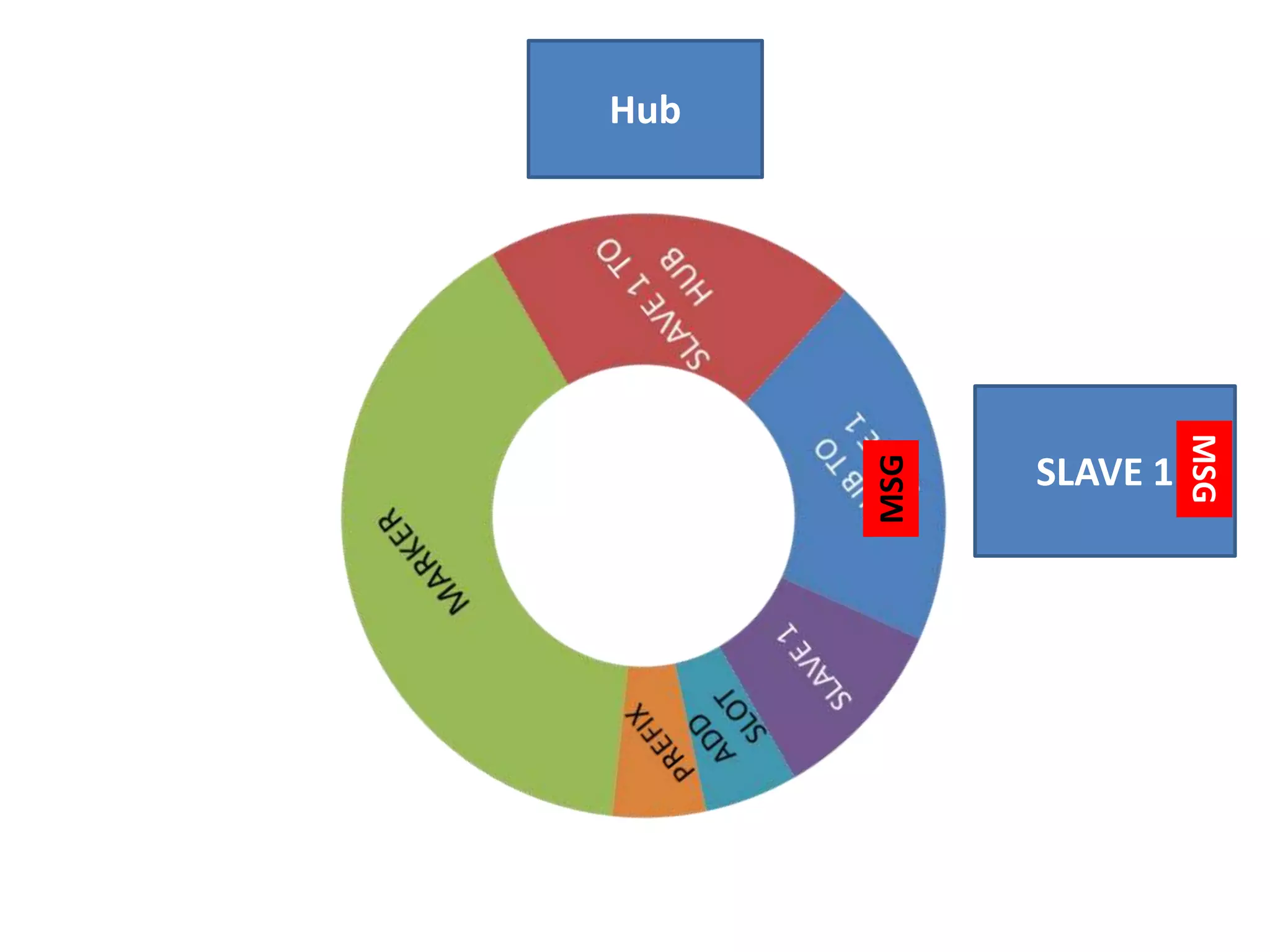
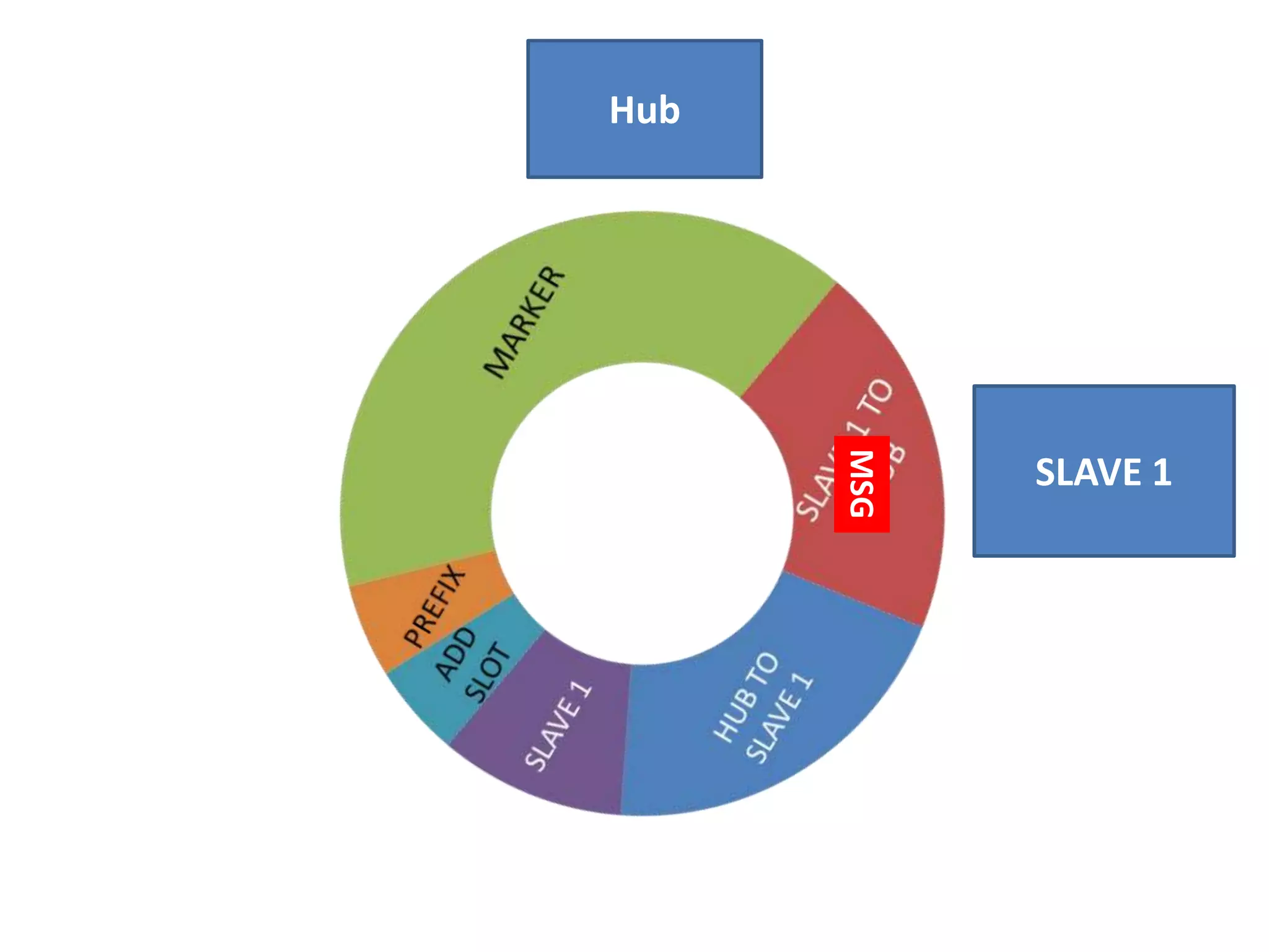
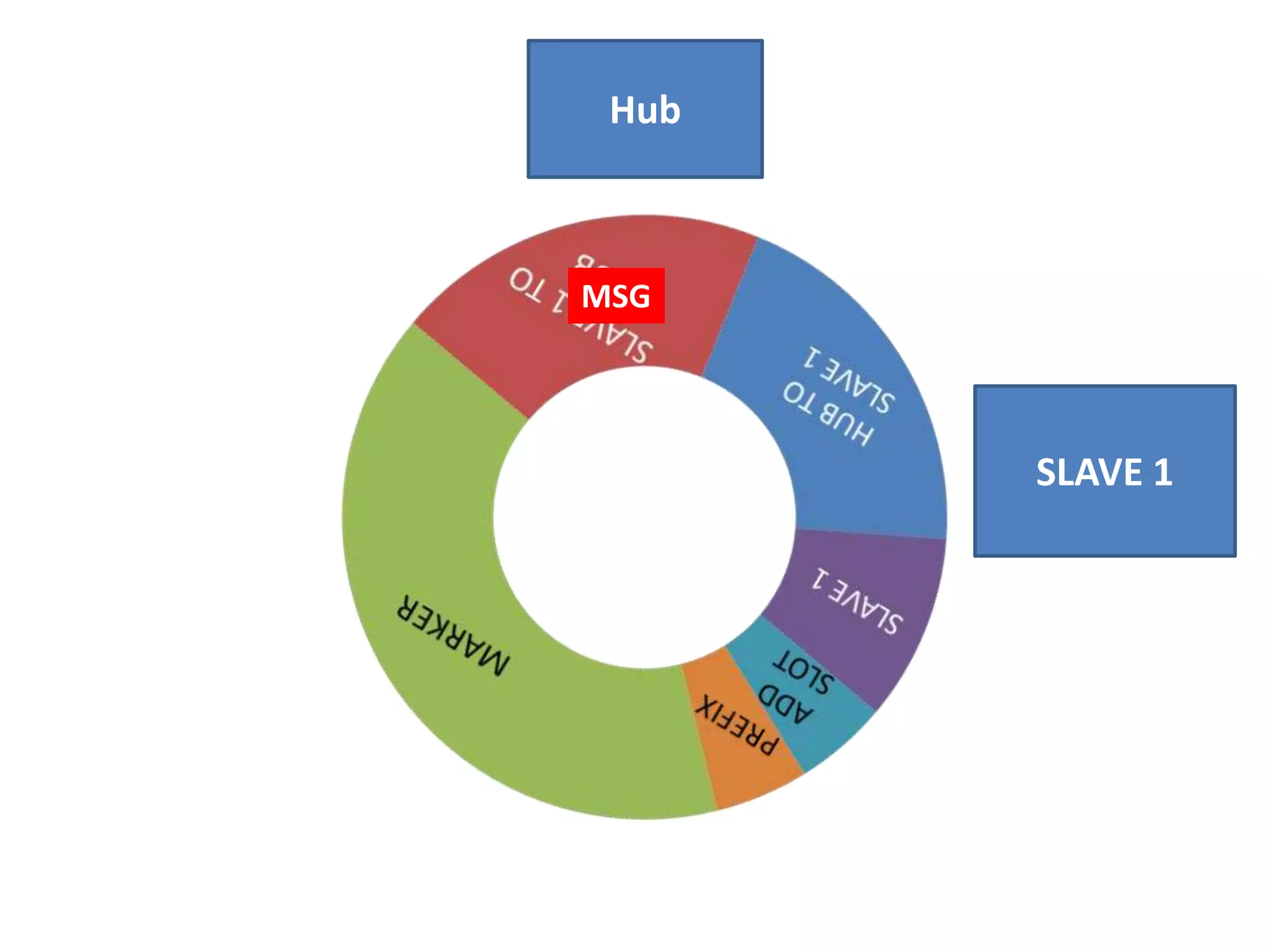

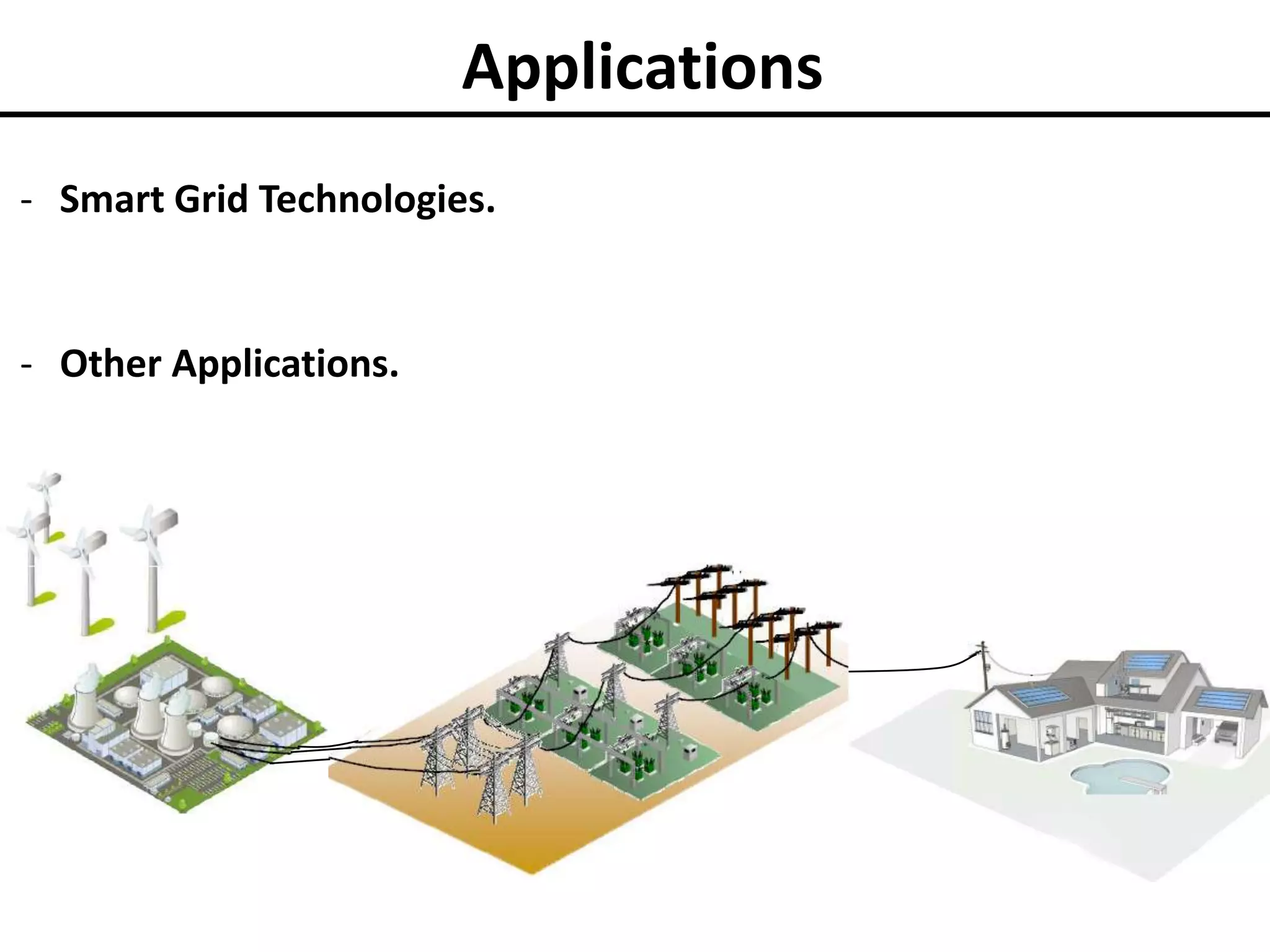
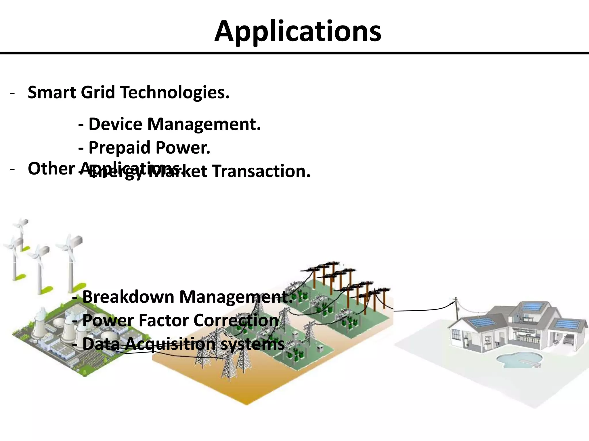


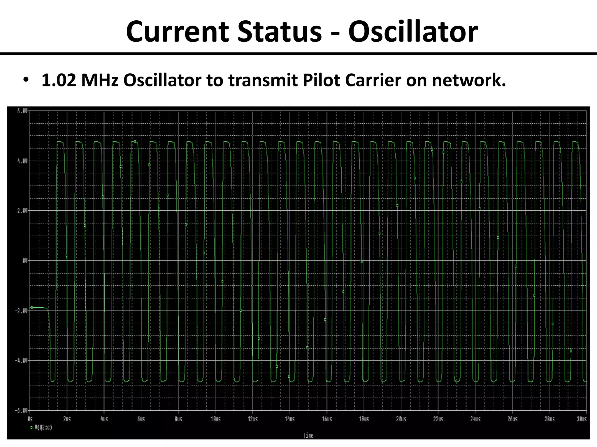
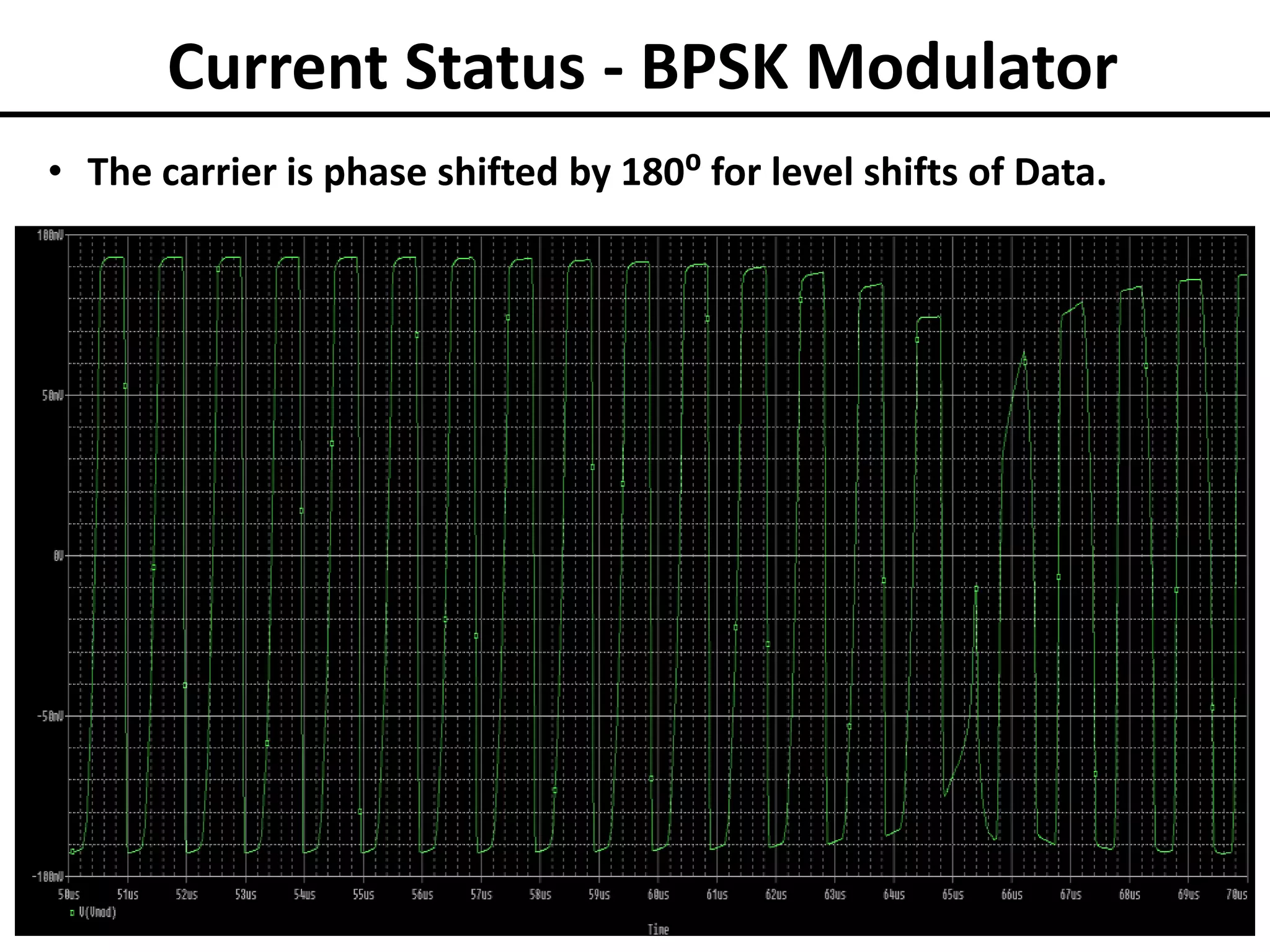
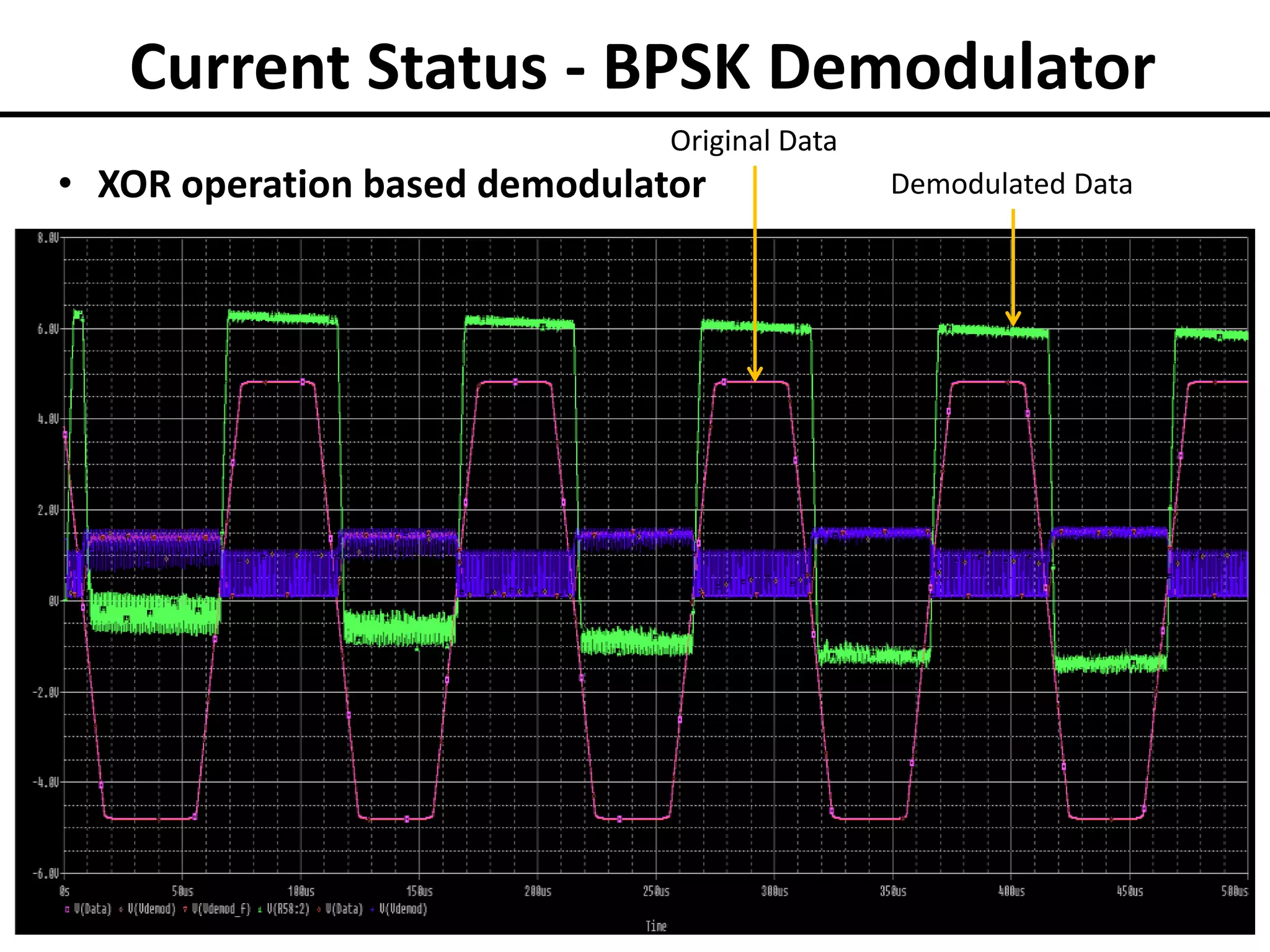
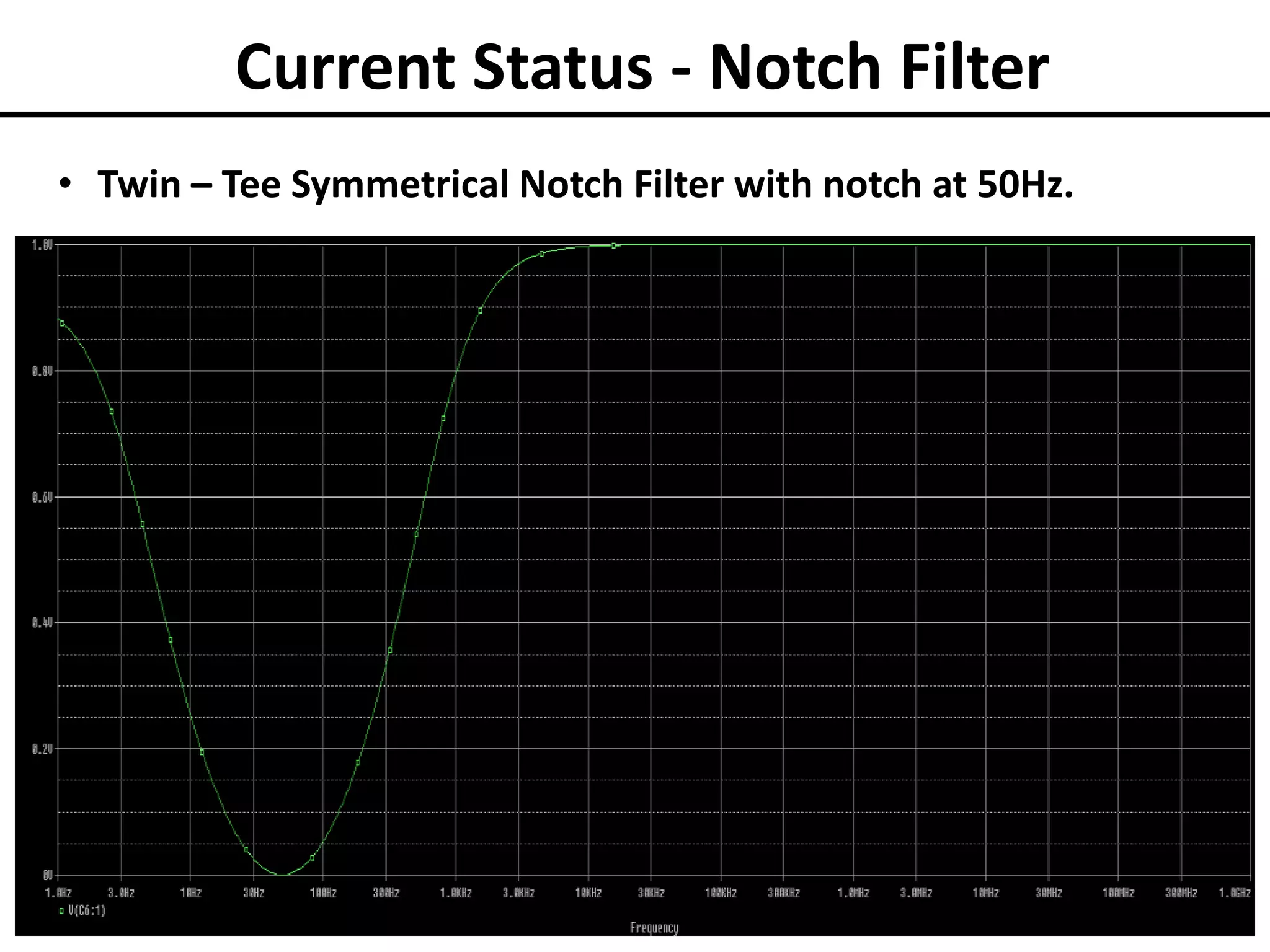

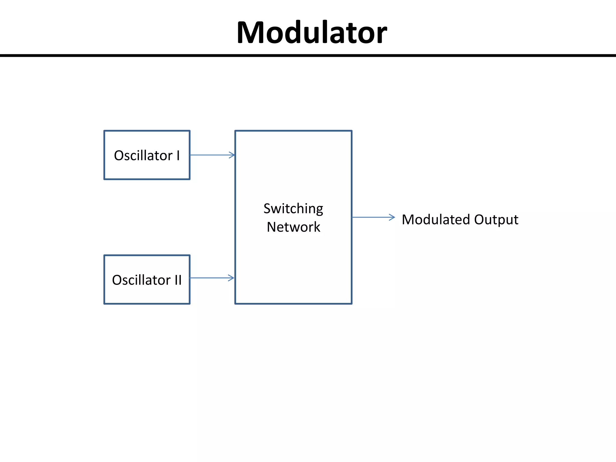
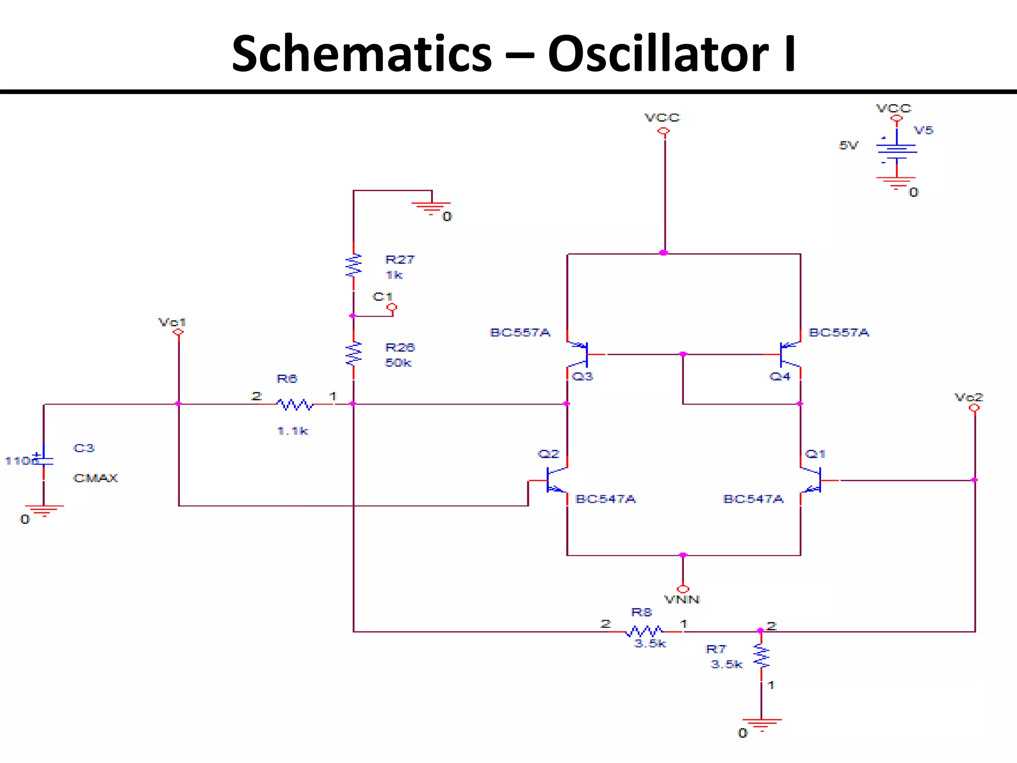
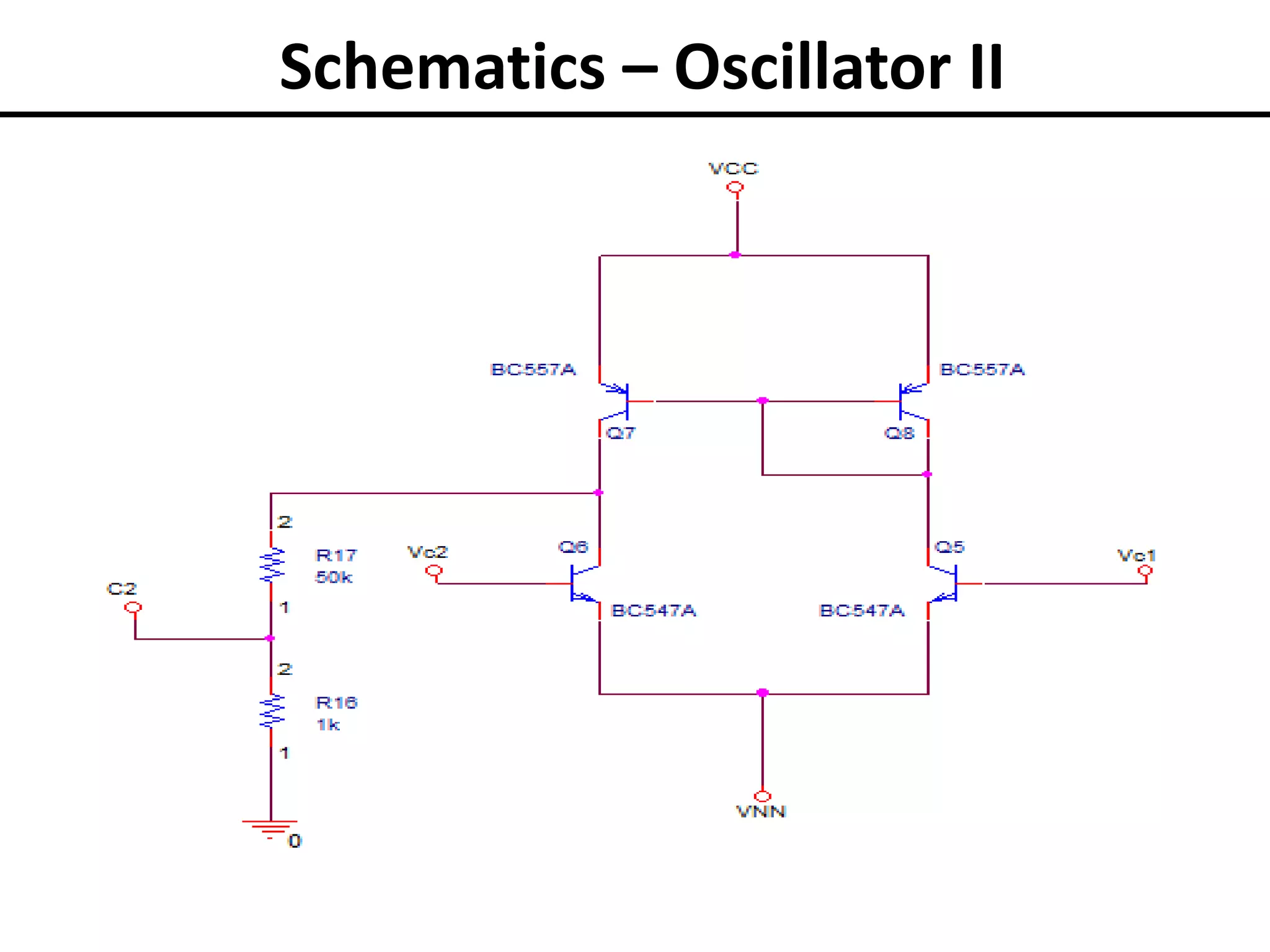
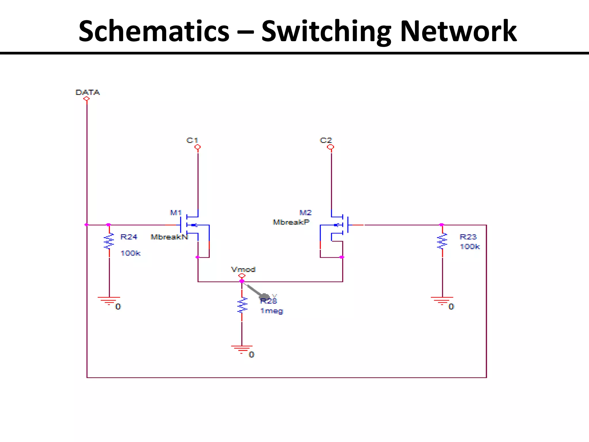
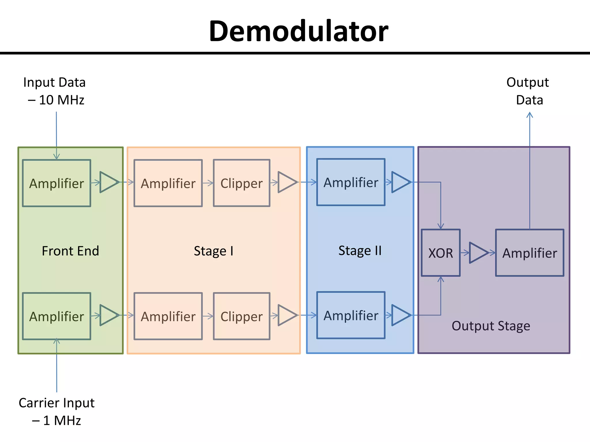
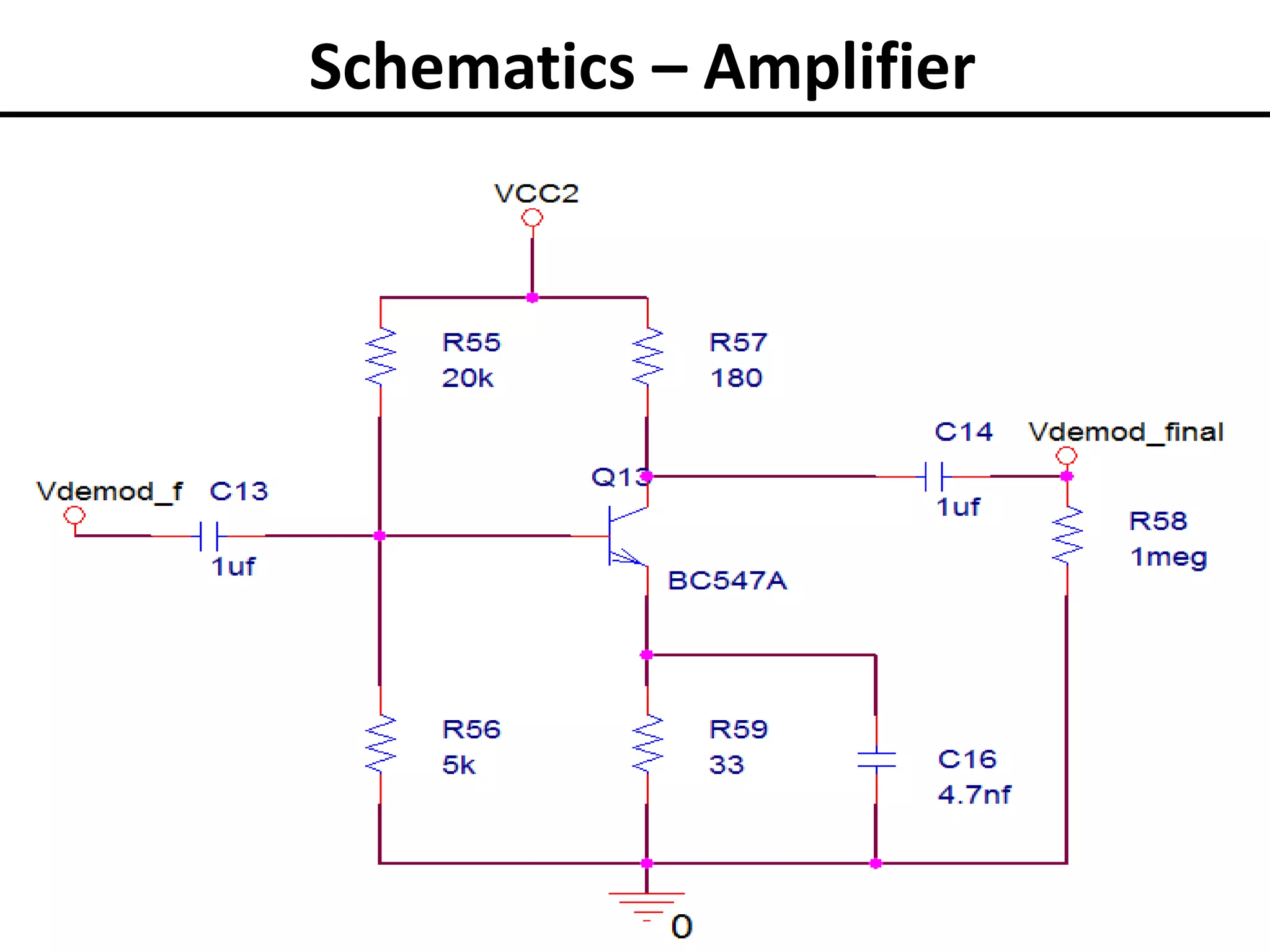
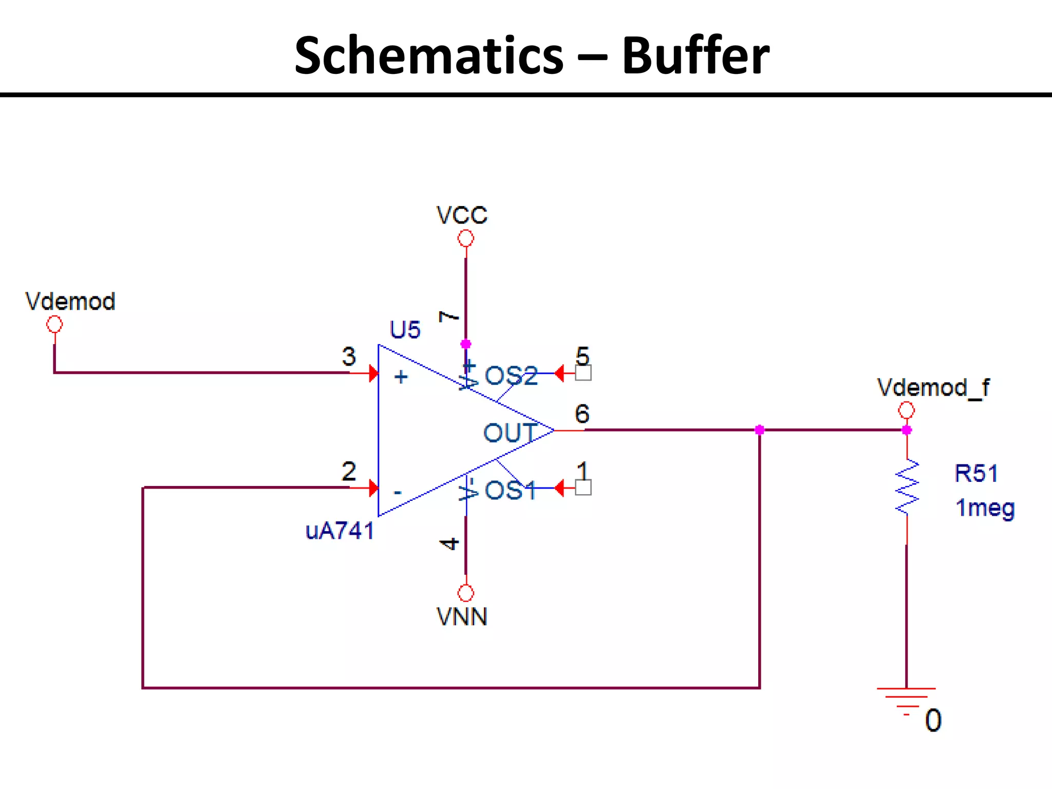
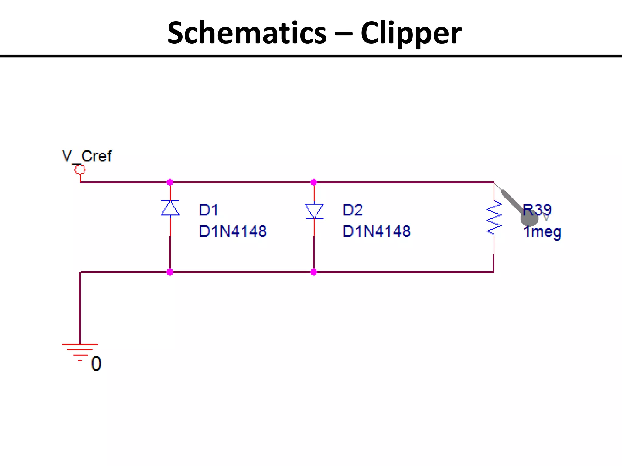
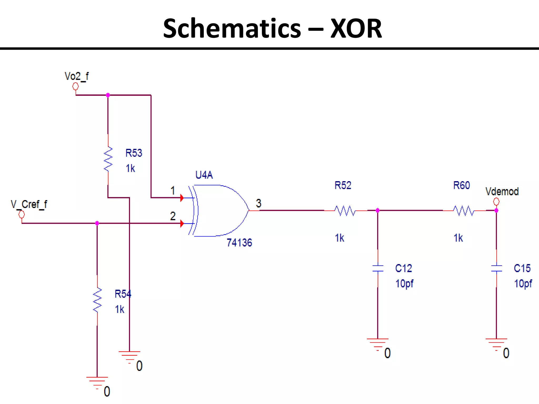

The document describes a proposed smart grid communication architecture consisting of Slave nodes and a Power Hub administrator node. The Slaves are low-profile nodes connected to appliances that communicate with the Power Hub over power lines. The Power Hub interfaces with system designers and implements control over the network through the Slaves. It maintains a database and uses a marker-prefix system for Slaves to register and communicate on the network. The document outlines applications like smart metering and provides status on the oscillator, modulator, demodulator, and notch filter designs for the power line communication system.