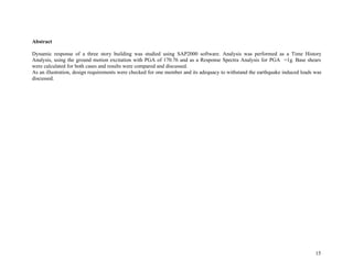
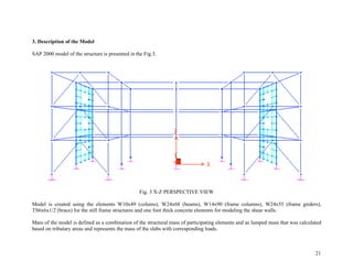
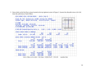
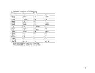
The document describes a 3D dynamic analysis of a 3-story steel building using SAP2000 software. A finite element model of the building was created and subjected to both response spectra analysis and time history analysis. The response spectra analysis yielded base shears of 2402.04kN and 3738.63kN in the X and Y directions respectively for a PGA of 1g. The time history analysis using the El Centro ground motion record yielded much higher base shears of 7.742x10⁵ kN and 2.89x10⁵ kN. Stress checks on structural members showed failure under the earthquake loads. The analyses demonstrated the building is not adequate to withstand seismic loads.
The document summarizes the structural analysis of two buildings - a residential bungalow and a public town hall structure in Ahmedabad, India. It describes the materials, dimensions, floors, and key structural elements of each building such as columns, beams, slabs. It also discusses the various loads acting on the structures like dead load, live load, wind load, and earthquake load. Safety norms regarding maximum floor space index, corrosion protection, and fire safety are also mentioned for building construction.
IJERA (International journal of Engineering Research and Applications) is International online, ... peer reviewed journal. For more detail or submit your article, please visit www.ijera.com
This document describes the design of a residential building located in S.V.Nagar, Puliyangudi. The 438.9 sqm building will be a G+1 framed structure. Structural elements like slabs, beams, columns were analyzed using STAAD Pro software and designed using the limit state method outlined in IS 456:2000. The building will include facilities like a portico, dining hall, drawing hall, kitchen, bedrooms, a study room, guest room, balcony, and staircase. Dimensional details of the structural elements are provided. Design of the slabs, beams, columns, footing, and staircase are discussed. The planning and design of the residential building was completed effectively using the limit state
This document summarizes the planning, analysis, and design of a residential apartment building project by three civil engineering students. It includes the building plans, structural drawings, analysis using STAAD Pro software, and manual design of structural elements like slabs, beams, columns, and footings. The building has four floors including a ground floor and is designed as per IS and NBC codes using M20 grade concrete and Fe415 grade steel.
AN INTERNSHIP REPORT ON RESIDENTIAL BUILDING CONSTRUCTIONAbhishek Singh
This document appears to be an internship report submitted by four students - Abhishek Singh, Naval Tej Singh Ahuja, Sahil Thakur, and Swapnil Singh - to their supervisor Mr. Kapil Bhardwaj at Universal Buildwell Pvt. Ltd. in Gurgaon, Haryana, India. The report provides details about a residential construction project called Universal Aura, including project specifications, building materials used, and work ongoing at the site during the students' summer internship from June 13 to July 13, 2016.
The document is a staff report for the City of Alamo Heights Community Development Services Department regarding a request for demolition and remodel of a single-family home located at 301 Encino. The applicant is proposing to demolish over 60% of the existing structure and add a second story addition. Staff found the existing structure has no historical or architectural significance. The report provides details on the proposed additions, lot coverage, bonuses utilized, and neighborhood context. It also includes the Architectural Review Board's recommendation to approve the proposed design as compatible with the neighborhood.
The document discusses site works and setting out for construction projects. It covers site analysis to explore site characteristics, site investigation for systematic inquiry before construction, site preparation with considerations for access, storage and safety. It also discusses the setting out process to lay out the building outline on site, including establishing reference lines, square lines, checking diagonals, and locating excavation lines. The goal is to ensure construction follows the design plans and account for any site issues.
minor project report on design of residential buildingtushar garg
This document is a minor project report submitted by Tushar Garg to Rajendra Kumar Khyalia for a Bachelor of Technology degree. It includes an acknowledgement, abstract, declaration, and table of contents sections. The content covers the aim of designing a residential building, including selecting a plot, surveying the site, requirements for residential buildings, building bye laws and regulations, room arrangements, and sanitation provisions. Drawings and photos are also included.
this summer training report is for civil engineering students and perfect format for shown to teachers. it is on foundation and basement design works in building.
PROJECT REPORT ON DESIGN OF A RESIDENTIAL BUILDINGAmritpal Singh
The document provides details of a project report for the design of a residential building in India. It includes an introduction, study area details, floor plans for 1BHK, 2BHK and 3BHK units, specifications, construction process and materials used such as cement, coarse aggregate, fine aggregate, and bricks. The summary is as follows:
The document is a project report for the design of a residential building in India that includes details of the site location, floor plans for different unit types (1BHK, 2BHK, 3BHK), building specifications, construction process, and materials used such as cement, aggregates, and bricks.
The document proposes building a commercial sport complex in Semenyih. It would provide sports facilities and promote healthy lifestyles. The complex would include a sports hall, swimming pool, gym, dance studio, changing rooms, and lockers. It would benefit the community by increasing activity levels, economic opportunities, and sense of well-being. The complex would be designed to be accessible, include green spaces, and integrate with the surrounding residential areas.
Lety Hernandez, Director of Community Development, presented plans for additions and interior remodel to an existing single-family residence located at 301 Encino. The plans include a combination of TPO and clay tile roofing in a terracotta color, stucco siding, and a maximum height of 31 feet 1 3/4 inches. The Architectural Review Board previously determined the structure was not significant and the proposed design was compatible with the existing and proposed streetscapes on Encino and Argyle. Public notification included postcards mailed to nearby property owners and notices posted online and on the property, receiving three letters of support and no opposition.
The document discusses key design parameters for efficient high-rise building floor plans based on an analysis of existing buildings in a residential development project comprising 27 towers over 40 acres. The analysis identified ratios of core area to construction area, walls/core/elevational features to floor plate, and core components like passages and lift lobbies that contribute to efficient plans. Acceptable ranges were established for these ratios based on minimum standards and their impact on cost and construction. The overall shape of buildings was also found to influence structural efficiency. The outcomes provide a tool to benchmark future designs for improved efficiency.
This document is a project report on the planning and design of a two-storey residential building along with a detailed cost estimate. It includes an introduction, discussion of building types and factors for planning buildings. It also covers building bye-laws, plan design including floor plans and layouts, structural designs for beams, slabs, columns and footings. Load calculations are presented, followed by a detailed cost estimate for the building construction including costs for excavation, concrete, brickwork, flooring, plastering and finishes.
Industrial training report of construction of the residential buildingsuraj jha
This document summarizes a presentation on a residential building construction project. It provides an overview of the project, including the location, number of floors, timeline, and project manager. It also describes the company undertaking the project, M k mehta enterprise, and its past projects. Additionally, it outlines the various steps of construction including site clearance, surveying, excavation, foundation, concreting, beams and columns. Key materials and equipment used are also summarized such as cement, aggregates, bricks, water, admixtures, and concrete pumping equipment. Building bylaws regarding plinth area regulations are also briefly mentioned.
This document provides an overview and methodology for a project to design and analyze a 7-story commercial building in Nepal to make it resilient against earthquakes. It discusses the motivation for building resilient structures, describes the strategic objectives of analyzing structural elements and using software for modeling. The methodology section outlines the process from title selection to final report preparation. The document also provides background on construction practices in Nepal, describes typical building features, and identifies the site location in Gaindakot, Nawalparasi.
The Marquette Plaza in Minneapolis, Minnesota was designed by architect Gunnar Birkerts and originally constructed in 1972 as the headquarters for the Federal Reserve Bank of Minneapolis. It features a unique catenary arch design supported by 16 cables strung between two towers, which gave the building its signature U-shape. The building underwent renovations from 1997-2002 that transformed it into a premier Class A office property. The suspension structure was chosen for its design to bridge over an open public plaza while maximizing sunlight and views. Loads are transferred between floors, towers, cables, and foundations through an innovative system of trusses, struts, and piles.
The document summarizes an industrial training report on the construction of a multistoried building. It describes two multistoried residential projects - Verna and Tana constructed by SI Property. Key details include the foundations using pile foundations and raft foundations, concrete mixes used, and reinforcement details of columns, beams and slabs. Amenities provided in the projects like parking, fitness center, kids play area are also mentioned. The report also provides information on new building materials seen during a visit to another project GIE Asteria, including Siporex blocks, Weber glue and fiberglass mesh.
A study on Skyscrapers. The Architectural, Economical, ecological, psychological aspects of the skyscraper are discussed. The Seismic factors, wind factors, emergency fire/elevator/sprinklers methods systematical designs. The vertical transportation of the skyscraper. The method of provision of elevators for all typology and front of house transportation and back of house services transportation are discussed. How facade becomes an important aspect in the design/fire safety etc. Case studies of different context (Coastal, Seismic, high wind zone, social sustainability) and different purpose of its own is discussed here.
Marquette Plaza, Minneapolis, Minnesota, United States.Mayur Waghulde
The Marquette Plaza in Minneapolis, Minnesota was designed in 1973 by architect Gunnar Birkerts. It uses an innovative catenary arch design supported by suspension cables between two towers to allow an open public plaza underneath. This unique structural system provides column-free interior spaces. The building was originally constructed as the headquarters for the Federal Reserve Bank of Minneapolis and underwent renovations in the late 1990s and early 2000s to transform it into a premier Class A office building.
The document summarizes two construction projects that utilized post-tensioned concrete slabs:
1) The MTC multifunctional shopping centre in Cakovec, Croatia, which featured a 97x78m building with a 16x10m column grid. The original design was replaced with post-tensioned flat slabs that reduced construction time by half and formwork expenses by 75% while increasing floor-to-floor heights.
2) The White City Shopping Development in London, one of Europe's largest retail centres, featuring over 120,000m2 of retail and commercial space. Structural Systems is responsible for post-tensioning work on level 20-30 slabs of up to 150x200
This document outlines a project to extend an existing reinforced concrete bungalow. It includes the floor plans and structural plans of the original 2-storey bungalow located in Iskandar Malaysia. The project requires students to propose a 30% extension to the bungalow in groups of two. Each group must design the extension, including floor plans, structural plans, and beam and column analysis to identify loads on the structure. The document provides background on the case study home and divides the project requirements and proposals between the student groups.
Monthly brief for structures in april (leisamis sde)Daniel Kariuki
This document contains a summary of construction progress for pipe culverts, box culverts, and bridges during the month of February. For pipe culverts, work included excavation, concrete pouring, and backfilling at several locations between km 36.859 to 31.249. For box culverts, formwork and concrete work was completed at km 22.824, 21.566, and 9.115. For bridges, concrete work continued on the second lift of an abutment at km 4.843 and the bearing beam capping of another abutment.
The Kohinoor Square project is a mixed-use skyscraper development under construction in Mumbai, India. It comprises a 203m main building with commercial and hotel space, and a 142m residential building. The complex utilizes sustainable design features like sky gardens, high-performance glazing, and rainwater harvesting. It has a composite structural system and pile raft foundation to support the tall towers. Floor plans show retail, office, and residential spaces of different sizes across multiple floors.
NSA provided architectural and engineering services for several projects including school additions and renovations for Southgate Community Schools and Ypsilanti School District, a senior living community called Fox Run, and a new fire station for the City of Novi. At Fox Run, NSA designed residential buildings, community buildings, and pedestrian bridges connecting the buildings. They utilized steel and concrete framing systems. At the Novi fire station, NSA employed concrete masonry walls and steel bar joists for the roof.
Effect of Positioning and Configuration of Shear Walls on Seismic Performance...IRJET Journal
1) The document analyzes the seismic performance of RC buildings with different shear wall configurations on both hilly and plain terrain.
2) Five building models are considered: without shear walls, with straight, L-shaped, T-shaped, and channel-shaped shear walls.
3) Response spectrum analysis is performed using ETABS software. Results for fundamental time period, base shear, and story displacements are compared between the models.
Lateral Load Analysis of Shear Wall and Concrete Braced Multi-Storeyed R.C Fr...ijsrd.com
Generally RC framed structures are designed without regards to structural action of masonry infill walls present. Masonry infill walls are widely used as partitions. These buildings are generally designed as framed structures without regard to structural action of masonry infill walls. They are considered as non- structural elements. RC frame building with open first storey is known as soft storey, which performs poorly during strong earthquake shaking. Past earthquakes are evident that collapses due to soft storeys are most often in RC buildings. In the soft storey, columns are severely stressed and unable to provide adequate shear resistance during the earthquake. . In this study, 3D analytical model of twelve storeyed buildings have been generated for different buildings Models and analyzed using structural analysis tool 'ETABS'. To study the effect of infill, ground soft, bare frame and models with ground soft having concrete core wall and shear walls and concrete bracings at different positions during earthquake; seismic analysis using both linear static, linear dynamic (response spectrum method) has been performed. The analytical model of the building includes all important components that influence the mass, strength, stiffness and deformability of the structure.
Lateral Load Analysis of Shear Wall and Concrete Braced Multi-Storeyed R.C Fr...ijsrd.com
This document analyzes the lateral load performance of different reinforced concrete frame models of a 12-story building using structural analysis software. Eight models are considered: a bare frame, fully infilled frame, frames infilled except the ground floor, and frames with shear walls, core walls or bracing in different configurations. Dynamic analysis shows fundamental periods are lowest for models with shear walls or bracing. Base shear and story drifts are highest for the bare frame and reduced by over 60% for infilled models. Models with ground soft-first story have increased drift, but shear walls or bracing can reduce drift by over 80% compared to the bare frame. Story displacements also decrease significantly with infilling or lateral load resisting elements.
IRJET- A Study on Seismic Analysis of RC Framed Structures on Varying Slo...IRJET Journal
This document presents a study on the seismic analysis of reinforced concrete framed structures located on varying slope angles, with and without shear walls. 12 models of a 10-story building were developed with slope angles of 0°, 11.25°, 22.5°, and 45° to analyze seismic performance. The models were analyzed using ETABS software for equivalent static and response spectrum analysis according to Indian seismic codes. Results for parameters like base shear, story shear, story displacement, and story drift were obtained and compared for models with shear walls at corners, corners and edges, and without shear walls. In general, models with shear walls performed better in reducing seismic demands.
IRJET- Study on Effect of Column Shape on Fire Resistance of CFST Column wi...IRJET Journal
The document studies the effect of column shape on the fire resistance of concrete filled steel tube (CFST) columns with a solid steel core through finite element analysis. Three column shapes are analyzed - circular, square, and rectangular. The analysis determines the temperature distribution over time along the column surfaces and identifies the shape with the maximum fire resistance. Preliminary static analysis is also performed. The results show that circular CFST columns with a steel core provide better fire performance than the other shapes.
The optimum location of shear wall in high rise r.c bulidings under lateral l...eSAT Journals
Abstract Shear walls are the structural elements of the horizontal force resisting system .shear walls have high influence stiffness and strength and provided to resist gravity loads as well as lateral loads caused by seismic and wind. So many literatures are available to analyze and design of shear wall. However the optimum location and its effects in high rise r.c.buildings is not much discussed in any literatures. In this paper the main aim is to find the effective, efficient, and optimum location of shear walls in high rise irregular R.C building. In this present study the optimum location of shear wall has been investigated with the help of three different models. Model 1 is bare frame structural system and other two models are dual type structural system with central core wall and corner shear wall. An earthquake load is calculated as per IS 1893(PART-1)-2002 and applied to (G+20) storey R.C building in zone-2 and zone-5. The analysis is performed using ETABS 9.7.4 Software package. Keywords: Shear wall, Irregular building, ETABS, analysis of structure, High rise building
The document proposes a design for UniArc Residences, a student residence building at Infrastructure University Kuala Lumpur using shipping containers. The 16-level building would house 990 rooms across 3 blocks using different sized containers. Structural analysis using STAAD.Pro shows the steel structure of columns, beams, and bolted connections can support the container loads. Shipping containers provide cost and construction benefits over traditional materials.
This paper describes the structural design of the Carterton Events Centre in New Zealand, focusing on its seismic resistant system consisting of dissipative timber rocking post-tensioning walls. The auditorium features 11 of these 180mm thick LVL walls, each 6.7m tall and 2.4m long, with a central slot for post-tensioned bars. Energy dissipation is provided by embedded mild steel rods. Non-linear dynamic analysis confirmed the design, showing the walls concentrate damage at interfaces while self-centering to their original positions after seismic events.
This paper summarizes the results of shake table experiments conducted on a full-scale base-isolated five-story steel moment frame building. The building was tested under three configurations: isolated with triple friction pendulum bearings (TPB), isolated with a combination of lead-rubber bearings and cross-linear bearings (LRB-CLB), and fixed to the shake table without isolation. Ground motions were applied using the world's largest shake table. The paper compares the response of the building under the different configurations and isolation systems. Based on experimental results, it was found that the TPB system provided greater attenuation of floor accelerations for ground motions with PGA larger than 10 m/s2, while the LRB
Post tensioned concrete walls & frames for seismic resistanceĐỗ Hữu Linh
This case study describes the innovative use of post-tensioned concrete in the construction of the David Brower Center in Berkeley, California. The building uses a hybrid system of post-tensioned concrete walls and frames to provide improved seismic performance and self-centering behavior after earthquakes. This allows the building to avoid permanent damage and remain functional. The post-tensioning reduces the amount of conventional reinforcement needed, making the building more compact and efficient to construct while also lowering its carbon footprint through the use of slag cement. Non-linear simulations were used to verify the design of this unique structural system.
IRJET - Performance Evaluation of Unsymmetrical High-Rise Building with Diffe...IRJET Journal
This document summarizes a study that evaluated the performance of different structural techniques for unsymmetrical high-rise buildings under critical lateral load conditions. Four structural models were analyzed using ETABS software: frame tube structure, tube in tube structure, braced frame structure, and frame structure with outrigger system. Parameters like story drift, lateral displacement, base shear, and story displacement were compared. Results showed that the braced frame structure performed best by reducing lateral displacement by up to 40% and story drift by 48-52% compared to the other structures. Therefore, the braced frame structure is recommended as the better system for high-rise buildings.
Dynamic Analysis of Steel Moment Resisting Frame on Sloping Ground with Braci...IRJET Journal
This document analyzes the dynamic behavior of steel moment resisting frame buildings on sloping ground with bracings and shear walls. Six different 12-story building models are considered: regular frame on sloping ground with bracings (Type A) and with shear walls (Type B). Dynamic analysis using response spectrum method is performed for different seismic zones and soil conditions. Results show that inclusion of bracings and shear walls reduces time period compared to regular frame, with shear walls producing the highest frequency of vibration. Modal analysis is carried out to understand dynamic behavior and time periods/frequencies are obtained for the first 12 vibration modes.
Seismic Analysis of Multi Storied Irregular Building using Flat Slab and Gri...IRJET Journal
This document analyzes the seismic performance of multi-story buildings with flat slab and grid slab structures in seismic zones III and V. Finite element software ETABS is used to model T-shaped and L-shaped buildings with 15 stories and both slab systems. Response spectrum analysis is conducted to determine parameters like base shear and storey shear. The results show that grid slab structures experience higher base shear values than equivalent flat slab buildings in both zones. In conclusion, grid slab structures perform poorer seismically compared to flat slab structures for the building geometries and conditions analyzed.
Dynamic analysis of steel tube structure with bracing systemseSAT Journals
Abstract Nowadays, competition towards rise of tall steel structures made certain factors are compulsory like serviceability and comfort of human relating to lateral loads caused by wind or earthquake. Earthquake is dangerous to the living beings in terms of its effects on manmade structures. Structures like tall buildings are built to resist gravity loads. However many tall buildings are not so resistant in lateral loads due to earthquake so need an improvement in resisting lateral loads. So there are many structural systems which resist lateral loads by varying orientation, addition of different structural systems. Like steel tubular structural system is considered and compared for their results against lateral forces and also by providing mega bracing system and diagrid bracing system. In this dissertation work, four structural systems are considered in which one is framed structure and rest are tubular system with addition of different bracing systems as mega bracing and diagrid bracing system. For the purpose 45 storey steel structure with rectangular plan of dimension 44mx24m uniform throughout the height is considered and analyzed for gravity and lateral loads using ETABS software. Its intention is to obtain the functioning characteristics like displacements, storey shear, time period, frequency, peak displacement and peak acceleration in both x and y direction to get most economical structure in all ways. Results shows that the steel tubular structure with mega bracing system performance is much better than the framed structure, tubular and tubular structure with diagrid bracing system. Keywords: Steel Tube Structure, Mega Bracing, Diagrid Bracing, Dynamic Analysis, ETABS, Time and History Analysis.
The document evaluates the seismic performance of St. Augustine Church in Lubao, Pampanga, Philippines using nonlinear static analysis. It summarizes the church's history and construction materials. A structural model of the church is created in ETABS using material properties obtained from adobe brick testing. Nonlinear static analysis is performed to determine the church's performance at different seismic levels-immediate occupancy, life safety, and collapse prevention. Retrofitting options like shotcrete are presented and their costs estimated to seismically upgrade weak parts of the structure. The analysis shows that portions of the church risk collapse in a major earthquake and retrofitting is recommended to improve seismic resistance.
The document provides a final report on the design of a luxury vacation home. Key points:
- The team designed a lightweight wooden substructure to hold up the home and withstand lateral loads of 35 lbs.
- The initial design was a tapered tower but it was difficult to construct accurately. The final design had vertical columns for easier construction.
- Structural analysis using slope-deflection and SAP2000 software found the design could withstand over 35 lbs of lateral load.
- Testing showed the structure failed at the connection between the testing apparatus and structure due to using a weaker glue than designed. The design successfully held over 7 lbs of lateral force.
IRJET- A Research on Comparing the Effect of Seismic Waves on Multistoried Bu...IRJET Journal
The document compares the effect of seismic waves on multistoried buildings with and without shear walls and flanged concrete columns. Three 10-story building models are analyzed using STAAD Pro: Model 1 without seismic resisting structures, Model 2 with concentrically located shear walls along the exterior, and Model 3 with flanged concrete columns along the exterior. Model 2 and 3 experience approximately 10% less lateral force and base shear compared to Model 1. Introducing shear walls or flanged columns improves seismic performance by increasing stiffness and reducing displacements, stresses, and forces in the building. While shear walls provide the greatest stability, flanged columns also enhance seismic resistance and may be more economical for some applications.
This document outlines a group project to design a structural extension for an existing reinforced concrete bungalow. It includes the following:
1. Introduction to the project, case study building, and structural systems used. Floor plans, structural plans, 3D models, and analyses are presented.
2. Individual proposals from three subgroups are presented. Each includes design briefs, architectural plans, structural plans, 3D models, and beam and column analyses.
3. One subgroup's proposal is for a two-story side extension adding a gym, bedrooms, and more. Plans, models, and structural element analyses are shown.
This document describes a finite element analysis of the deformation of different beam designs for a cantilevered third story balcony. Students analyzed beams made of 5"x5" square tubing, 4"x4" I-beams, and 6"x4" rectangular tubing, with and without additional truss supports, under a pressure load of 2.82 psi. Meshes of different densities were used and results like deformation, stress, and safety factor were compared for each design. Adding truss supports significantly reduced the total deformation in all cases. The 5"x5" square tubing design was found to perform best with low deformation and a safety factor above 1.
This document summarizes a dissertation analyzing the seismic performance of an irregular 11-story building with AAC blocks using the response spectrum method in ETABS. The objectives were to analyze and design the building economically according to codes while studying the effects of earthquake and wind loads. The methodology involved defining materials, loads, response spectra, and mass/diaphragm in ETABS to analyze and design the building. Results showed maximum displacements of 25.95mm, story shear of 3.138kN, and overturning moment of 75.980kNm. Reinforcement percentages ranged from 3.76% at the base to 0.8% in upper stories. The study concluded the AAC blocks provided a lighter and more econom
2. • MOUNTAIN CABIN 1
• PARK PAVILION 2
• SANTA MONICA OFFICE BUILDING 3
• GOLF CART BRIDGE 4
• BEACH FRONT HOUSE 5
• 3D DYNAMIC ANALYSIS WITH SAP2000 14
TABLE OF CONTENTS
3. The simple design of a 20’ by 40’ cabin uses 20’ span beams
between the walls to create the mezzanine and roof. The
design of the roof reflects the inside of the cabin, since a roof
is build upon beams that reside on load bearing walls below it.
MOUNTAIN CABIN
ARCH 205A
fall 2006
1
4. The pavilion design is simple, but the structure
provides a basic shelter while allowing visitors to
enjoy the park. The triangular motif of the structure
is unique and acts as a bridge across the lake to an
island at the center.
The three columns support the cantiliver beams to
provide those under it shade while maintaining a full
view of the park.
PARK PAVILION
ARCH 205A
fall 2006
2
5. The following is a group project with two
students in a group. This is a steel frame
building with columns 18ft apart in the
east-west direction and 33 ft apart in the
north-south direction, 27ft from a solid wall to
the north.
The first floor is designed with a 15 ft
overhang on the exterior of the building. This
floor is split into two areas, a retail area on
the west side, and a gallery on the east side.
A large skylight opens up between the two
areas, with a fountain and benches for people
to enjoy.
The second floor is designed for office space.
There is a walkway that circulates around the
building, with a skylight above to allow light in
the halls. This walkway is broken as one exits
the building and walks onto a balcony
overlooking the skylight on the first floor and
the street below on the other side. Offices line
the exterior of the west and south wall facing
the street. All utilities are along the north wall
away from the streets.
ARCH 205B
SPRING 2007
SANTA MONICA
OFFICE BUILDING
3
6. The design of a 64’golf cart
bridge uses a double arch
suspended deck bridge to solve
the forces. The leaning arches
allow resistance to the horizontal
wind and seismic forces. Through
the use of cables, the concrete
slab can overcome the moment
from the long span.
BRENT WOOD, CALIFORNIA
ARCH 305A
fall 2007
GOLF CART BRIDGE
AND CLUB HOUSE
To keep the same motif
throughout the golf course, the
clubhouse is designed with
three steel arches breced to
resist lateral forces. Rods are
used to hang the roof from the
arches, creating a flexible open
space below with no colums
and glass walls.
Lobby & Observation Area
Women's
Locker
Men's
Locker
Women's
Toilet
Men's
Toilet
MaintenanceMaintenance
FLOOR PLAN
SCALE 3/16"=1'
CONNECTION DETAIL
SCALE 3/4"=1'
CONNECTION DETAIL
SCALE 3/4"=1'
WALL SECTION DETAIL
SCALE 3/4"=1'
WALL SECTION DETAIL
SCALE 3/4"=1'
SOUTH ELEVATION
SCALE 3/16"=1'
EAST ELEVATION(SIMILAR TO WEST)
SCALE3/16"=1'
SECTION 1
SCALE3/16"=1'
SECTION 2
SCALE3/16"=1'
4
7. For this project we were assigned to design a pentagon shaped house,
with the south side facing the beach. We had a group of three, with I as
the group leader.
The house has a mezzanine on the north side, so that the open studio
would have a grand view of the ocean. The mezzanine includes two
beds and two baths, with a lounge area that is open to the ocean view
and studio below.
On the first floor there is half bath, kitchen, a laundry/mechanical, and
a storage. There are two entrances to the house, an utility entrance
leading to the storage and kitchen, and a grand entrance on the east
side to the two story studio with a view of the ocean.
SANTA MONICA, CALIFORNIA
ARCH 305B
SPRING 2008
BEACH FRONT HOUSE
5
16. 14
3-D DYNAMIC ANALYSIS OF A
THREE STORY BUILDING
USING SAP2000
by
Angela Su
As a part of laboratory project for CE 458 class
Department of Civil and Environmental Engineering
Viterbi School of Engineering
University of Southern California
Spring 2008
17. 15
Abstract
Dynamic response of a three story building was studied using SAP2000 software. Analysis was performed as a Time History
Analysis, using the ground motion excitation with PGA of 170.76 and as a Response Spectra Analysis for PGA =1g. Base shears
were calculated for both cases and results were compared and discussed.
As an illustration, design requirements were checked for one member and its adequacy to withstand the earthquake induced loads was
discussed.
18. 16
Table of Contents
1. Introduction
2. Description of the structure
3. Description of the model
4. Analysis and Results
4.1. Time History Analysis
4.2. Response Spectra Analysis
5. Conclusions
6. References
19. 17
1. Introduction
For the purpose of learning some of the major application possibilities of SAP2000 software, a fictitious structure is created.
Structure is a three story steel building, with frame configuration that can be used in a typical office building design. Main structural
system consists of steel frames, positioned in both horizontal directions, combined with reinforced concrete (RC) shear walls.
Main tasks were:
• Creating the finite element model, based on the assigned characteristics of structural elements, assumptions of the rigid floor
diaphragms and lumped mass calculation.
• Performing 3D dynamic analysis using Response Spectra approach, for longitudinal and for transversal direction, for peak
ground acceleration (PGA) 1g. Maximal physical displacements are obtained using RSS method. Base shear was calculated for
both horizontal directions and stresses plotted for the shear walls. Stress check was performed for the first floor column.
• Performing 3D dynamic analysis using Time History approach for the given acceleration excitation record, with PGA =170.76.
Selected time histories of the joint displacements and base shear are plotted.
Obtained results were discussed and it is found that the results of the two dynamic analysis show very different results in base shear,
the response spectra gives a se shear of X=2402.04K and Y=3738.63K, while maximum base shear for the El Centro earthquake is
X=7.742x10⁵
K, and Y=2.89 x10⁵
K. The El Centro earthquake’s acceleration exceeds the 5 modes we analyzed in response spectrum
analysis, since it yielded a larger base shear. The building is found to be not adequate to endure the earthquake in both analyses. We
checked the structure through sheer stress of a bottom member where it is larges, which failed, for the response spectrum analysis. For
time history the deflection at the roof, which would be the largest, exceeded the acceptable limit.
20. 18
2. Description of the Structure
Analyzed structure is a three story still building, with typical office building design characteristics. Story height is 12ft, for all stories.
Base of the structure is of irregular shape, with maximal dimensions of 84 ft by 40 ft.
Main structural system consists of orthogonal positioned still frames – moment resistant and brace frames and of shear walls.
Structural system of the floor slabs is not specifically defined, but slabs are assumed to be rigid in their own planes, what corresponds
to type of RC slab systems. The weight of the slabs, including the weight of the flooring, perimeter walls, services load, etc. is defined
to be 120 lb/sq ft and roof weight to be 110 lb/sq ft.
Gravity load is carried by the system of longitudinal and transversal still frames (Fig. 1 and Fig. 2).
Main lateral load for transversal direction is carried by two shear walls and by moment resistant frame. Each shear wall is 20 ft long
and 1ft thick RC system. Walls are located at the outside transversal frames and symmetrical with respect to central transversal axis.
Moment resistant frame, with one 20 ft span is located along the central transversal axis (Fig. 1 and Fig.2)
Main lateral load for the longitudinal direction is carried by two moment resistant frames and two brace frames. Frames are positioned
along the outside longitudinal frames, and symmetrical to the central transversal axis (Fig. 1 and Fig.2).
Characteristics and types of structural elements are assigned and presented on the Fig.1 and Fig. 2.
Foundation type was not specified, but for purposes of Response Spectra Analysis, soil type 1 was used.
Results obtained by the Response Spectra Analysis were compared to results obtained by the Time History Analysis.
23. 21
3. Description of the Model
SAP 2000 model of the structure is presented in the Fig.3.
Fig. 3 X-Z PERSPECTIVE VIEW
Model is created using the elements W10x49 (colums), W24x68 (beams), W14x90 (frame columns), W24x55 (frame girders),
TS6x6x1/2 (brace) for the still frame structures and one foot thick concrete elements for modeling the shear walls.
Mass of the model is defined as a combination of the structural mass of participating elements and as lumped mass that was calculated
based on tributary areas and represents the mass of the slabs with corresponding loads.
24. 22
Calculation of tributary areas is shown on the Fig. 4.
Fig.4 TRIBUTARY AREAS
AxRoof 110psf AxFloor 120psf
Node1 A1=100 F=11k M=.3416 F=12k M=.3727
Node2 A2=220 F=24.2k M=.7516 F=26.4k M=.8199
Node3 A3=240 F=26.4k M=.8199 F=28.8k M=.8944
Node4 A4=200 F=22k M=.6832 F=24k M=.7453
Node5 A5=320 F=35.2k M=1.093 F=38.4k M=1.193
Node6 A6=240 F=26.4k M=.8199 F=28.8k M=.8944
Node7 A7=100 F=11k M=.3416 F=12k M=.3727
Node8 A8=100 F=11k M=.3416 F=12k M=.3727
Each story of the shear wall has a window with dimensions 10ft by 6ft located at the center of the bay.
25. 23
4. Analysis and Results
Study of dynamic response of the structure is performed using:
• Response Spectra Analysis, for X and Y direction separately, based on normalized response spectra graph, for PGA of 1g. It is
assumed that excitation at all supports is the same.
• Time History Analysis, for the given acceleration excitation at supports, assuming that earthquake strikes at an angle of 45
degrees from the global X axis of the structure.
26. 24
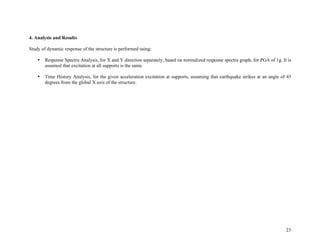
4.1. Response Spectra Analysis
Based on normalized response spectra graph, and for PGA =1g, for soil type 1, response spectra calculation was performed for two
orthogonal directions independently.
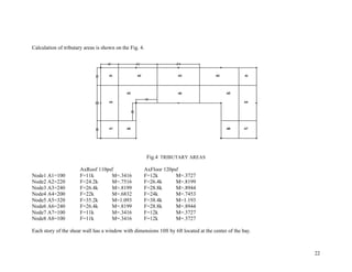
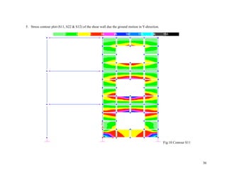
Model of the structure is created such that floor slabs remain rigid during the translations and torsional rotations.
There are advantages in using the response spectrum method of seismic analysis for prediction of displacements and member forces in
structural systems. The method involves the calculation of only maximum values of the displacements and member forces in each
mode. The use of computers has sped up the process and allows one to run many time history analyses in a short period of time.
The “Mode Superposition Method” is used to “uncouple” the dynamic force equilibrium equation. The number of degrees-of-freedom
is equal to the number of lumped mass in the system. The mode superposition method is a powerful method used to solve for the many
unknowns in a dynamic response analysis. Using a computer all types of loading can be accurately approximated by linear functions
with a small time increment.
.. . ..
[M]{D} + [C]{D} + [K]{D} =-[M][R]{Dg}
{D}=[!]{q}
.. . ..
{q} + [GM]-1
[GC]{q} + [GM]-1
[GK]{q}=[GM]-1
[GL] {Dg}
.. . ..
{q} + [2"#]{q} + [#2
]{q}=[$] {Dg}
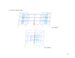
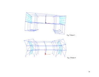
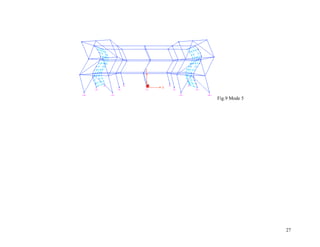
1. The natural frequencies and vibration modes using SAP2000.
mode Period (T) (s) f = 1/T (1/s) ! = f*2" (rad/s)
1 0.3045 3.284072 20.62397
2 0.1576 6.345178 39.84772
3 0.1182 8.460237 53.13029
4 0.1092 9.157509 57.50916
5 0.0627 15.94896 100.1595
27. 25
2. The first 5 vibration modes
Fig. 5 Mode 1
Fig. 6 Mode 2
30. 28
3. Stress check on the first floor column located in the top rightmost corner of Figure 2. Assume the allowable stress to be 0.66
times the yield stress of steel (36ksi).
0.66 x 36ksi x (0.1x144) = 342.14ksi = 49268.7k-ft2
< 5214.38 member fails
31. 29
4. Base shear in each case in both directions.
SpecX SpecY
X Y X Y
28.32 330.51 0.10 593.82
44.49 0.94 0.7 3.11
57.55 5.3x10^-3 0.06 6.98
44.49 0.94 0.03 3.13
28.32 331.15 0.08 599.09
24.55 330.55 0.07 594.09
7.19 0.24 8.27X10^-3 0.81
24.79 5.3x10^-3 0.03 6.98
7.53 0.25 9.33X10^-3 0.82
24.55 331.19 0.06 599.37
526.97 0.45 0.4 0.81
526.97 0.25 0.4 0.81
526.64 0.25 0.4 0.82
526.95 0.45 0.4 0.82
TOTAL
2399.31 1327.17 2.73 2411.46
BASE SHEAR IN X=2399.31+2.73=2402.04K
BASE SHEAR IN Y= 1327.17+2411.46=3738.63K
32. 30
5. Stress contour plot (S11, S22 & S12) of the shear wall due the ground motion in Y-direction.
Fig.10 Contour S11
34. 32
Fig.12 Contour S12
The shear panels for S11 and S22 accumulate stress from top to bottom so that the bottom corners receive the most stress. For S12
the stress gathers at the center of the shear panel rather than the edges.
35. 33
6. Results
In class we learned to find the period for a 1D structure, a complex 3D structure, such as our model would be extremely
complicated to calculate. From the period, shape functions were applied to find the mode shapes of the structure. To solve for
displacement, uncouple equations were used. Using the RSS method, one can convert modal displacement back to physical
displacement. Next we checked the stress of different members of the structure and its shear walls. It appears our structure is not
adequate to withstand the base shear of X=2402.04K and Y=3738.63K.
36. 34
4.2 Time History Analysis
For the given acceleration excitation, defined by 936 points, equally spaced on 0.02 seconds (50 points per second), with peak
amplitude of 215.212 cm/sec2, at about 6.68 seconds, Time History Analysis is performed. It is assumed that earthquake strikes the
structure at an angle of 45 degrees measured from the global X axis of the structure.
Time history dynamic analysis of structures uses actual past earthquake data to apply acceleration to the building from the base. It is
assumed that all support excitations are the same and the response of the building is computed at each point of given acceleration. Iti s
also assumed that all floor diaphragms are rigid so that they move as one. Using the same differential equations as above we solve for
the structural response.
.. . ..
[M]{D} + [C]{D} + [K]{D} =-[M][R]{Dg}
{D}=[!]{q}
.. . ..
{q} + [GM]-1
[GC]{q} + [GM]-1
[GK]{q}=[GM]-1
[GL] {Dg}
.. . ..
{q} + [2"#]{q} + [#2
]{q}=[$] {Dg}
37. 35
1. Time history displacements of the joint located on the roof at the bottom left corner of Figure 2.
Fig. 12 TIME HISTORY OF JOINT
38. 36
2. Plot the time history of the base shear in each direction. Determine the max shear.
Fig. 13 BASE SHEAR IN Y
39. 37
Fig. 14 BASE SHEAR IN X &Y
3. Results
The maximum base shear is 7.742x10⁵
K for the X direction, and 2.89 x10⁵
K in the Y direction. When the two graphs are
plotted against each other it is obvious that shear in X is much larger than Y.
Looking at the roof joint displacement, the maximum is 7.07ft of displacement. This is a very large displacement for a 3 story
building, 12ft each.
40. 38
5. Conclusions
A complex 3D structure, such as the one we modeled, would be hard analyze and would take a long time to calculate. Using software
such as SAP2000 analysis can be done in minutes, even seconds. However one must use their engineering judgment to interpret these
results. One should check to see that the results are reasonable. Software can be used to help in the analysis process, but if one does
not have any engineering background, one would not even recognize a major error the program had made. Errors happen a lot,
whether by wrong inputs, such as wrong units, or errors in modeling, where joints are not connected properly, and sometimes the
structure is just beyond the limits of the program.
The results of the two dynamic analysis show very different results in base shear, the response spectra gives a se shear of X=2402.04K
and Y=3738.63K, while maximum base shear is X=7.742x10⁵
K, and Y=2.89 x10⁵
K. Modes are used to determine the base shear in response
spectra, while time history uses actually earthquake data to apply acceleration to the building. We can then conclude that El Centro earthquake
exceeded the five modes we analyzed in response spectra analysis. Both analysis shows that the building is not adequate. Through response spectra
we determined that building would fail. Response spectra results showed an unacceptable displacement in the roof. The shear walls would not be
able to take that large of a deflection.
To perform analysis, one must simplify the model, and make assumptions, such as rigid floor slabs, and equal support excitation. This makes the
model move as a inverted pendulum. Without these assumptions the process and time to make analysis would take much longer, and yield results
we may not necessarily need. What we want is the maximum. Through the use of safety factors and assuming the largest excitation, we make sure
the structure is stronger than it would need to be.
41. 39
6. References
1. Class notes for CE 458 Lab and class, Univ. of Southern California, Civil Eng. Dept., Spring 2006.
2. “Personal Communication” with Professor Sanja Ivanovic.