
Recommended
More Related Content
What's hot
What's hot (20)
Viewers also liked
Viewers also liked (12)
Similar to 784323_Tebevert_dsp_gb
Similar to 784323_Tebevert_dsp_gb (20)
More from Bernadette Polintan
More from Bernadette Polintan (13)
784323_Tebevert_dsp_gb
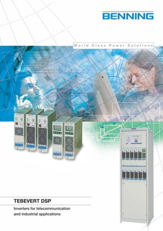
- 1. W o r l d C l a s s P o w e r S o l u t i o n s TEBEVERT DSP Inverters for telecommunication and industrial applications 784323.08GB09/2010pausDesign&Medien,BocholtSubjecttoalterations.Printedonchlorinefreepaper. DSP_Tebevert_D_GB_F_CZ_PL_23.qxd 01.10.2010 10:21 Uhr Seite 6
- 2. 42 B E N N I N G W o r l d C l a s s P o w e r S o l u t i o n s TEBEVERT DSP reliable and comfortable General Information The Tebevert DSP inverter system featuring DSP- technology (Digital Signal Processing) can be used in a wide array of telecommunication and industrial applications. The introduc- tion of enhanced DSP controls and higher semi-conductor switching frequencies improves power density, operating efficiency while dramatically reducing physical size and weight. The Tebevert DSP inverters feature the latest in paralleling technology allowing multiple inverter modules to be reliably paralleled to support higher power levels or N+1 redundancy. The regulation and monitoring is provided via digital signal processors (DSP) programmed with next generation regula- tion and control algorithms. The CAN (Control Area Network) bus communication interface provides high reliability com- munication between the system components while a built-in serial interface provides service access for system status and software update. The DSP Inverter system features: • DSP- Technology (Digital Signal Processing) • Simple installation and maintenance via hot plug technology • Compact design • Adjustable voltage and frequency • Display with extensive Monitoring Inverter system with static bypass Sub rack Tebevert 1,5 kVA Tebevert 2,5 kVA Tebevert 1,0 kVA System configuration The Tebevert DSP inverter incorporates a modular design providing easily configurable, expandable solutions. Systems can be quickly configured to suit most applications without any load interruption. A maximum of 6 inverter modules can be installed in a single sub rack (picture 1), and parallel connection of two sub racks can be used for system redundancy or increased power capacity (picture 2).The Tebevert DSP inverters can be con- structed to support a maximum output power of 12 kVA (1 kVA inverter), 18 kVA (1,5 kVA inverter) or 30 kVA (2,5 kVA inverter). Systems can also be configured with an optional static bypass (EUE) module. In this configuration, a maximum of 5 inverter modules plus a static bypass module can be installed in a single sub rack (picture 3), or 11 inverters and one static bypass are possible in a two sub rack configuration (picture 4). DSP_Tebevert_D_GB_F_CZ_PL_23.qxd 01.10.2010 10:20 Uhr Seite 1
- 3. 3 B E N N I N G W o r l d C l a s s P o w e r S o l u t i o n s TEBEVERT DSP with Static Bypass increased system reliability Picture 7: The access to sensitive menu levels is controlled by multi-level passwords. Picture 6: Single line diagram Load voltage U = 227V Load current I = 36.0A Load frequency F = 50Hz Load power Real power Complex power Reactive power Mains voltage U = 230V Measured values Inverter 1 Inverter 2 • • Inverter n Real power P = 8.6kW Complex power S = 9.3kVA Reactive power Q = 2.8kVAr Inverter n Input voltage Output voltage Output current Main Menu Measured values Device management System settings Clear all messages Service portal Software version Display Measured values Load voltage Load current Load frequency Load power Mains voltage Inverter values Menu levels EUE 12 kVA EUE 30 kVA Display static bypass Static bypass (EUE) The optional static bypass module (EUE) increases system reliability by providing automatic switching between the inverter output and the AC mains source providing protection against load interruptions caused by severe overloads or the unlikely inverter system failure. The Tebevert DSP no-break switching provides computer grade power capable of powering the most sensitive electro- nic loads. Front panel pushbuttons and a graphical digital display provide a wide range of supervisory functions, and enable easy monitoring and modification of system controls. Static bypass Nominal power rating [kVA] 12 30 DC input [V] 48 / 60 24 /48 / 60 DC input range [%] +20, -15 *Nominal mains (AC) input [V] 120 / 220 / 230 / 240 Mains (AC) input range [%] ±15 *Nominal mains (AC) frequency [Hz] 50 / 60 Mains (AC) frequency range max. ±3 %; Synchronize area of the inverter *Inverter nominal voltage [V] 120 / 220 / 230 / 240 Nominal output power [kVA] 12 30 Nominal output voltage [V] 120 / 220 / 230 / 240 Voltage range / static max. ±15 % at mains priority, max. ± 1% at inverter priority *Nominal output frequency [Hz] 50 / 60 Max. frequency deviation ±3 %; (±1 % crystal control) *Nominal output current [A] 100 / 54,6 / 52,5 / 50,6 250 / 136,4 / 130,4 / 125 Power factor range 0,7 ind. to 0,8 cap. Overload rating 500 % for 100 ms Transfer time 2ms (DIN VDE 0558 part5; IEC 146-4) *Operation modes Inverter priority / Mains priority Mechanical design 19" part rack Dimensions H x W x D [mm] 261 x 74 x 374 261 x 74 x 481 [in] 10,3 x 2,9 x 14,7 10,3 x 2,9 x 18,9 Protection class IP 20 (without plug) Painting RAL 7035 for front panel Indicators Fault Operation Display for system status and measurement Connections Plug Weight [kg] 5 7 [lbs] 11 15,4 *The settings for 220 / 230 / 240 V systems are software configurable. Included in the menu driven display screen is an easy to view system single line diagram plus detailed system operational information, status and alarms (picture 6). The user control pushbuttons provide local access to measurement values, component status, system adjustments and service options (picture 7). The static bypass module can be configured to operate in an on-line (inverter priority) or off-line (mains priority) modes. The access to sensitive menu levels is controlled by multi- level passwords. DSP_Tebevert_D_GB_F_CZ_PL_23.qxd 01.10.2010 10:21 Uhr Seite 4
- 4. 4 B E N N I N G W o r l d C l a s s P o w e r S o l u t i o n s TEBEVERT DSP multiple options Mechanical bypass MBS Systems with static bypass also include a mechanical main- tenance bypass switch providing voltage free system mainte- nance or the safe removal of the static bypass module without load power interruptions (picture 5). The maintenance bypass is mechanically interlocked with the static bypass module preventing the accidental removal of the static bypass module which could result in a loss of AC voltage at the load. Picture 5: Panel MBS System Inv 1 Inv 2 Inv 6 AC-Load DC System 1 System 2 Inv 1 Inv 2 Inv 6 Inv 7 Inv 8 Inv 12 AC-Load DC 1 DC 2 System 1 System 2 AC Mains Inv 1 Inv 5 Inv 6 Inv 7 Inv 11 AC-Load DC 1 DC 2 System AC Mains Inv 1 Inv 5 AC-Load DC 1 Picture 3: Parallel operation of 5 inverters and a static bypass Picture 4: Parallel operation of 11 inverters and a static bypass Picture 1: Parallel operations of 6 inverters Picture 2: Parallel operation of 12 inverters in two sub racks DSP_Tebevert_D_GB_F_CZ_PL_23.qxd 01.10.2010 10:20 Uhr Seite 2
- 5. B E N N I N G W o r l d C l a s s P o w e r S o l u t i o n s TEBEVERT DSP technical opportunities Inverter Nominal power rating [kVA] 1 1,5 2,5 DC input voltage [V] 48 / 60 24 48 / 60 DC input range [%] +20, -15 *Disconnection value [V] 40,8 / 51 20,4 40,8 / 51 *Connection value [V] 49 / 61,3 24,5 49 / 61,3 Input current at nominal real power [A] 18,7 57,5 46,7 Ripple of the input voltage max. 5 % eff. Nominal real power (cos ϕ = 0,8) [kVA] 1 1,5 2,5 Nominal real power [kW] 0,8 1,2 2,0 *Output voltage [V] 120 / 220 / 230 / 240 Static regulation [%] ±1 *Nominal current (cos ϕ = 0,8) [A] 8,33 / 4,55 / 4,35 / 4,17 -,- / 6,5 / 6,8 / 6,2 20,83 /11,36 /10,87 /10,42 *Output frequency [Hz] 50 / 60 Regulation frequency [%] ±0,1 with crystal control Mains control of frequency [%] ±3 Power factor range 0,7 ind. to 0,8 cap. Efficiency at 100% [%] 90 87 90 Voltage waveform [%] Sine-wave Output distortion factor [%] ≤ 2 at linear load Short circuit behavior 10 Arms for 4 sec, 15 Arms for 4 sec, 25 Arms for 4 sec, then cut-off then cut-off then cut-off Overload capacity [%] 200 for 4 sec, then reduction to 120 for 60 sec, then cut-off Continuous overload [%] 110 Crest factor load 2.8:1 (higher crest factor possible at reduced output current) Radio interference Limiting class B to EN 55022 Noise level 55 dB (A) at fan operation Ambient temperature [°C] 0 to +40 Installation height Up to 1000m (3,300 ft) above sea level Climatic environment conditions IEC 721-3-3 (3k3) Humidity class F (0-95% non-condensing) Cooling Temperature controlled forced ventilation Protection class 1 to EN 60950 Mechanical design 19" subrack (rack or cabinet mount.) 23" relay rack mounting Dimensions H x W x D [mm] 261 x 74 x 353 261 x 74 x 463 261 x 74 x 463 [in] 10,3 x 2,9 x 13,9 10,3 x 2,9 x 18,2 10,3 x 2,9 x 18,2 Protection class IP 20 (without plug) Painting RAL 7035 for front panel Indicators Fault Output voltage present Parallel operation DC input within limits Bargraph for output power Connections plug Weight [kg] 5 8 8 [lbs] 11 17,6 17,6 Option 48 V (1 kVA and 2,5 kVA) also available with output voltage of 110 V /115 V / 120 V *The settings for 220 / 230 / 240 V units are software configurable. DSP_Tebevert_D_GB_F_CZ_PL_23.qxd 01.10.2010 10:20 Uhr Seite 3
- 6. 3 www.benning.de ISO 14001 ISO 9001 Natural Resourc es Energy Efficienc y CO2 SCC B E N N I N G W o r l d C l a s s P o w e r S o l u t i o n s 784323.08GB09/2010pausDesign&Medien,BocholtSubjecttoalterations.Printedonchlorinefreepaper. BENNING worldwide Austria Benning GmbH Elektrotechnik und Elektronik Eduard-Klinger-Str. 9 A-3423 St. Andrä-Wördern Tel. 0 22 42 / 3 24 16-0 Fax 0 22 42 / 3 24 23 E-Mail: info@benning.at Belarus IOOO BENNING Belarus ul. Derzinskogo, 50 BY-224030, Brest Tel. 0162 / 22 07 21 Fax 0162 / 22 07 21 E-Mail: info@benning.brest.by Belgium Benning Belgium Power Electronics Z. 2 Essenestraat 16 B-1740 Ternat Tel. 02 / 58 287 85 Fax 02 / 58 287 69 E-Mail: info@benning.be Croatia Benning Zagreb d.o.o. Trnjanska 61 HR-10000 Zagreb Tel. 1 / 63 12 280 Fax 1 / 63 12 289 E-Mail: info@benning.hr Czech Republic Benning CR s.r.o. Zahradní ul. 894 CZ-293 06 Kosmonosy (Mladá Boleslav) Tel. 3 26 72 10 03 Fax 3 26 72 25 33 E-Mail: benning@benning.cz France Benning Conversion d’énergie 43, avenue Winston Churchill B.P. 418 F-27404 Louviers Cedex Tél. 0 / 2.32.25.23.94 Fax 0 / 2.32.25.08.64 E-Mail: info@benning.fr Germany Benning Elektrotechnik und Elektronik GmbH & Co.KG Factory I: Münsterstr. 135-137 Factory II: Robert-Bosch-Str. 20 D-46397 Bocholt Tel. 0 28 71/ 93-0 Fax 0 28 71/ 9 32 97 E-Mail: info@benning.de Great-Britain Benning Power Electronics (UK) Ltd. Oakley House Hogwood Lane Finchampstead GB-Berkshire RG 40 4QW Tel. 0118 9731506 Fax 0118 9731508 E-Mail: info@benninguk.com Hungary Benning Kft. Power Electronics Rákóczi út 145 H-2541 Lábatlan Tel. 033 / 50 76 00 Fax 033 / 50 76 01 E-Mail: benning@vnet.hu Italy Benning Conversione di Energia S.r.L Via 2 Giugno 1946, 8/B I-40033 Casalecchio di Reno (BO) Tel. 0 51 / 75 88 00 Fax 0 51 / 61 67 655 E-Mail: info@benningitalia.com Netherlands Benning NL Power Electronics Peppelkade 42 NL-3992 AK Houten Tel. 0 30/ 6346010 Fax 0 30/6346020 E-Mail: info@benning.nl Poland Benning Power Electronics Sp. z o.o. Korczunkowa 30 PL-05-503 Glosków Tel. 0 22 / 7 57 84 53 Fax 0 22 / 7 57 84 52 E-Mail: biuro@benning.biz P. R. China Benning Power Electronics (Beijing) Co., Ltd. Tongzhou Industrial Development Zone 1-B BeiEr Street CN-101113 Beijing Tel. 010 61568588 Fax 010 61506200 E-Mail: info@benning.cn Russian Federation OOO Benning Power Electronics Moscow region, Domodedovskiy district, Domodedovo, Severny zone, Tel. (495) 967 68 50 Fax (495) 967 68 51 E-Mail: benning@benning.ru Slovakia Benning Slovensko, s.r.o. Kukuričná 17 SK-83103 Bratislava Tel. 02 / 44459942 Fax 02 / 44455005 E-Mail: benning@benning.sk South America Benning Office South America Lavalle 637 AR-1876 Bernal, Buenos Aires Argentina Tel. 54/ 911 5498 2515 E-Mail: info-argentina@benning.es South East Asia Benning Power Electronics Pte Ltd 85, Defu Lane 10 #05-00 SGP-Singapore 539218 Tel. (65) 6844 3133 Fax (65) 6844 3279 E-Mail: sales@benning.com.sg Sweden Benning Sweden AB Box 990, Hovslagarev. 3B S-19129 Sollentuna Tel. 08 / 6239500 Fax 08 / 969772 E-Mail: power@benning.se Switzerland Benning Power Electronics GmbH Industriestrasse 6 CH-8305 Dietlikon Tel. 044 / 8057575 Fax 044 / 8057580 E-Mail: info@benning.ch Spain Benning Conversión de Energía S.A. C/Pico de Santa Catalina 2 Pol. Ind. Los Linares E-28970 Humanes, Madrid Tel. 91/ 6048110 Fax 91/ 6048402 E-Mail: benning@benning.es Ukraine Benning Power Electronics 3 Sim'yi Sosninykh str. UA-03148 Kyiv Tel. 044 / 501 40 45 Fax 044 / 273 57 49 E-Mail: info@benning.ua U.S.A. Benning Power Electronics, Inc. 11120 Grader Street USA-Dallas, TX 75238 Tel. 214 5531444 Fax 214 5531355 E-Mail: sales@benning.us DSP_Tebevert_D_GB_F_CZ_PL_23.qxd 01.10.2010 10:21 Uhr Seite 5