Download to read offline
![IJRET: International Journal of Research in Engineering and Technology eISSN: 2319-1163 | pISSN: 2321-7308
_______________________________________________________________________________________
Volume: 04 Issue: 05 | May-2015, Available @ http://www.ijret.org 474
APPLICATION OF FINITE ELEMENT ANALYSIS IN EFFECTIVE
DESIGN OF FLIGHT CONTROL CIRCUITS IN A TYPICAL LIGHT
HELICOPTER
Mallikarjun R Killedar1
, Ramesh Katti2
, Palli Naresh Babu3
1
Mtech (Design Engineering), KLE’S Dr. MSSCET, Belgaum
2
Assistant Professor, KLE’S Dr. MSSCET, Belgaum
3
Engineer, STRESS Group, RWR&DC, HAL, Bangalore
Abstract
The objective of this project work is to effectively design and analyze the helicopter flight control circuits. The design process
involves FE method to assess the directional control circuit. Displacement, stress, strain energy values are obtained for the circuit
for different load cases and optimum design is obtained for safe helicopter flight controls for critical maneuvers.
In a helicopter the rotor blade is operated using mechanical flight control system consisting of elements like push-pull rod, links,
bell crank levers, structural supporting brackets etc. There is a certain amount of reduction in stiffness and strength of elements of
the circuit due to stretch in these elements resulting in false control surface deflections.
This project work focuses on the application of FEM in design, analysis and optimization of directional flight control circuit using
ALTAIR HYPERMESH and MSC NASTRAN software’s. FEM techniques have been extensively used in this study to simulate the
control circuit mechanism.
Keywords: directional control circuit, finite element analysis, displacement, strain energy
--------------------------------------------------------------------***----------------------------------------------------------------------
1. INTRODUCTION
The flight controls modify the pitch angle of the main and
tail rotors allowing the pilot to Control helicopter flight by
modifying its altitude, speed and heading [2].
In general, the flight control circuits are designed to have
minimum stretch in the circuit, not exceeding 20%, as per
aircraft standards [1]. Ground tests are carried out to
confirm the stretch and stiffness values in the control circuit.
Redesign of circuit is carried out, if necessary, to obtain
acceptable results. The process is generally iterative in
nature, and has both cost and time implications.
Directional/Pedal Control circuit of a typical light helicopter
has been chosen for the case study. A detailed FE model is
analyzed to predict the stretch and stiffness values more
accurately.
1.1 Directional/Pedal FCS in a Typical Light
Helicopter
In the light helicopter under consideration, the directional
control circuit mechanism is fully mechanical, consisting of
combination of push pull rods, bell crank levers, supporting
Brackets etc. as shown in figure-1.
Series of push pull rods are used between the controls. Bell-
crank levers are used at regular intervals to reduce the length
of push-pull rods for improving its buckling margins. These
are also used to change the direction and leverage of the
control circuit.
Fig -1: directional/pedal control circuit
2. FINITE ELEMENT ANALYSES
FEA software Altair Hyper mesh is used as pre and post
processor, and MSC NASTRAN is used as a solver. FE
model with appropriate boundary conditions has been used
to obtain the optimum lever ratios and load distributions
such that the stretch values are within acceptable limit.](https://image.slidesharecdn.com/applicationoffiniteelementanalysisineffectivedesignofflightcontrolcircuitsinatypicallighthelicopter-160903075423/75/Application-of-finite-element-analysis-in-effective-design-of-flight-control-circuits-in-a-typical-light-helicopter-1-2048.jpg)
![IJRET: International Journal of Research in Engineering and Technology eISSN: 2319-1163 | pISSN: 2321-7308
_______________________________________________________________________________________
Volume: 04 Issue: 05 | May-2015, Available @ http://www.ijret.org 475
A detailed FE model has been developed using the 1D
element (CROD, CBAR) to represent the push-pull rods,
bolts, etc. 2D elements (CQUAD4) to represent the frame to
which the pedal circuit parts are attached. 3D elements
(CTETRA) to represent the bell crank levers, T-levers,
offset bell cranks, pedal bracket, fork end, pedal lever,
supporting brackets etc.
Fig -2: FE model showing directional circuit parts
Fig-3: FE model showing parts attached to the lower
helicopter frame
Fig-4 (a) - : components in detail – pedal lever, screw shaft,
fork end, T-lever
This FE model consists of all the components in the control
circuit along with supporting structure that attaches these
FCS components to the lower helicopter structure. Details of
the FE model of various components are shown in figure-2,
figure-3 and figure-4.
Fig-4 (b): components in detail – supporting brackets, offset
lever
Table – 1: mesh details
Element type Total number of elements
CBEAM 680
CBAR 132
CROD 10
CQUAD4 71080
CTETRA 440526
2.1 Design Limit Loads
The Directional control components are designed to
withstand the Limit Pilot Loads as specified in FAR 27.397
and 27.399 [5]. Design Limit Load for directional circuit is
shown in the table below.
Table – 2: design limit loads
Channel Design limit
loads
Direction
Yaw control
(pedal)
589 N Left pedal
forward
Displacement and strain energy values of the parts and the
whole model is obtained.
3. ANALYSIS AND RESULTS
Static analysis was carried out for the pilot loads mentioned
in FAR [5] using MSC Nastran SOL-101 [4]. The detailed
FE model with the optimum leverages obtained by
analyzing the parts individually has been analyzed for loads
mentioned earlier. The displacements and strain energy plots
for the same are shown in Figure-5 and Figure-6.](https://image.slidesharecdn.com/applicationoffiniteelementanalysisineffectivedesignofflightcontrolcircuitsinatypicallighthelicopter-160903075423/75/Application-of-finite-element-analysis-in-effective-design-of-flight-control-circuits-in-a-typical-light-helicopter-2-2048.jpg)
![IJRET: International Journal of Research in Engineering and Technology eISSN: 2319-1163 | pISSN: 2321-7308
_______________________________________________________________________________________
Volume: 04 Issue: 05 | May-2015, Available @ http://www.ijret.org 477
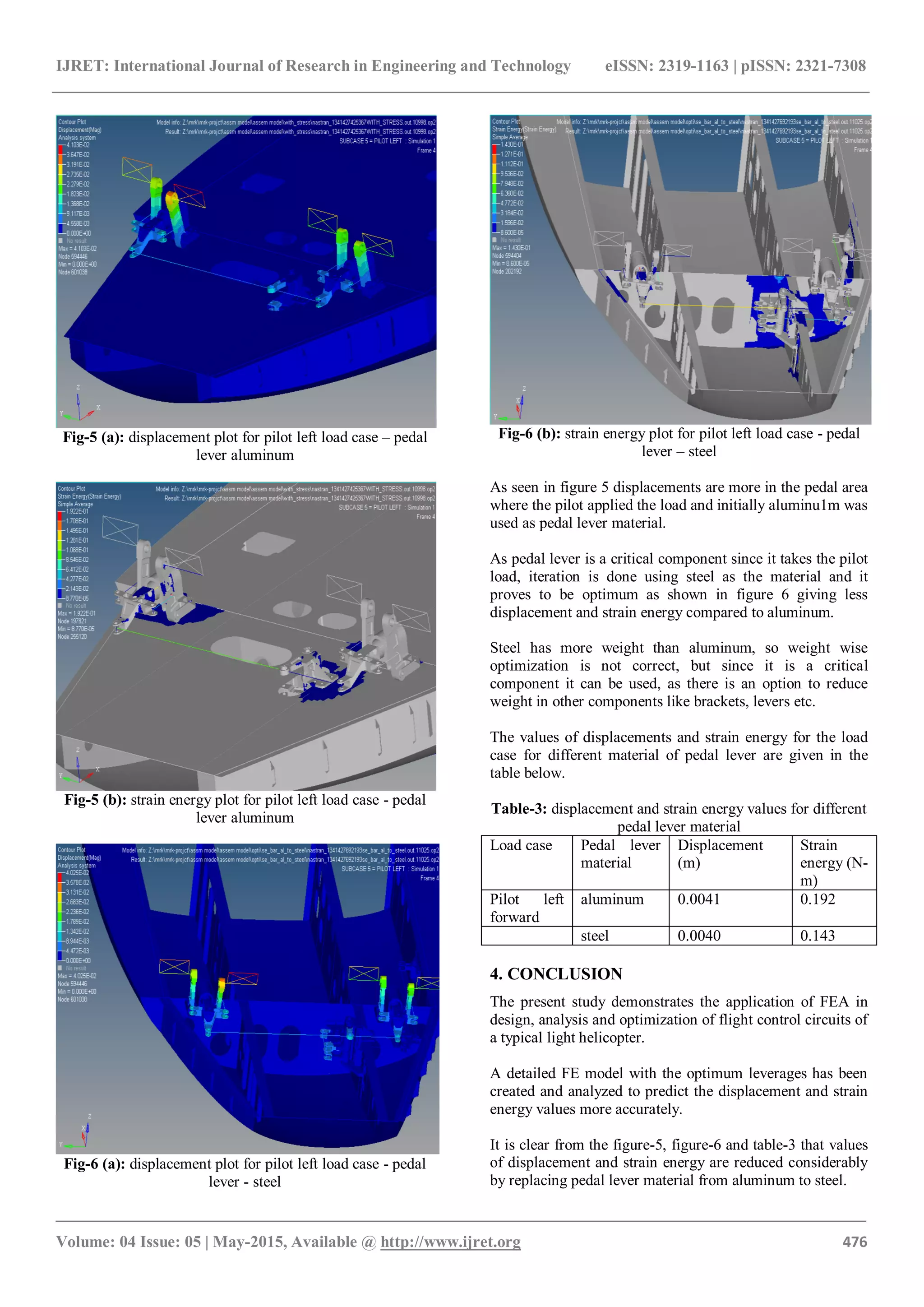
Since strain energy is reduced impact on the frame by the
brackets is reduced, thus less energy is consumed during
displacement of the parts, thus giving required travel of all
the links.
Using steel as pedal lever material increases weight, but
since it is a big control system involving many parts,
increase in weight is affordable by considering the strength
and stiffness parameters.
REFERENCES
[1]. http://nal-ir.nal.res.in/12026/2/jeas_0414_1064.pdf
[2]. http://en.wikipedia.org/wiki/Helicopter_flight_controls
[3]. Altair Hyper works 12.0 Documentation, Altair
Engineering Inc.
[4]. MSC Nastran 2012 Documentation, MSC Software
Corporation.
[5]. FAA Federal Aviation Regulations (FAR)
BIOGRAPHIES
Mallikarjun R Killedar, Presently studying in final
semester of MTECH (DESIGN ENGINEERING) in KLE’S
Dr. MSSCET, BELGAUM. Completed B.E
(MECHANICAL ENGINEERING) from the same college
in 2013.
Ramesh Katti, Presently working as an assistant professor
in KLE’S Dr. MSSCET, BELGAUM. Completed B.E
(MECHANICAL ENGINEERING) and MTECH (DESIGN
ENGINEERING) from KLE’S Dr. MSSCET, BELGAUM.
Palli Naresh Babu, Presently working as an engineer in
STRESS GROUP, RWR&DC, HAL, and BANGALORE.
Completed BTECH in AERONAUTICAL ENGINEERING
from IIT MADRAS.](https://image.slidesharecdn.com/applicationoffiniteelementanalysisineffectivedesignofflightcontrolcircuitsinatypicallighthelicopter-160903075423/75/Application-of-finite-element-analysis-in-effective-design-of-flight-control-circuits-in-a-typical-light-helicopter-4-2048.jpg)

This document presents a study on the design and finite element analysis (FEA) of flight control circuits in a light helicopter, focusing on optimizing the directional control circuit to ensure safe operations during critical maneuvers. Using Altair Hypermesh and MSC Nastran, the authors analyze various load cases to determine displacement and strain energy values, ultimately suggesting the use of steel over aluminum for the pedal lever to enhance stiffness and strength. The findings indicate that while using steel increases weight, it is a reasonable trade-off for improved structural integrity in the helicopter's control system.