Download to read offline
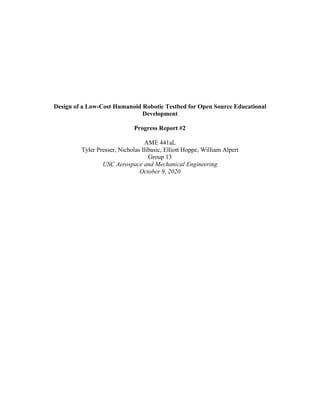

![Figure 5. Detailed view of RoBOT’s tensioning system below the right hip joint. The hip casing
has been shown with transparency to provide clarity on how the system is connected. Belts are
shown as yellow lines and are included for illustrative purposes.
The next steps to be completed in NX are the primary FEA analysis and motion simulations for
the robot’s legs.
Selection of Actuators
In order to determine which motors should be used in each joint, calculations based on MATLAB
simulations and the LIPM models mentioned in PR1 were performed. As a result, two different
actuators were selected to meet the needs of RoBOT’s design: AK10-9 and AK80-9. The AK10-
9 is the stronger of the two with a rated torque of 18 Nm and weight of 820 grams. It will be used
to rotate the femur linkage as well as the knee. Since the ankle torque requirements are much less,
power will be supplied by the AK80-9 motor, which has a rated torque of 9 Nm and weight of 485
grams. It is also cheaper at a cost of $580 instead of $699 for the AK10-9. Both of these motors
make use of a planetary gearbox in which the input shaft and output shaft are aligned, allowing for
a high torque density.
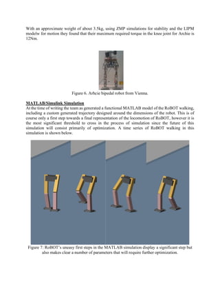
The math used to calculate the actuator choices can also be validated by comparing RoBOT’s
actuator choice to existing robots. One such robot is the Archie Robot from the Vienna Institute of
mechanics and Mechatronics [3].](https://image.slidesharecdn.com/progressreport2-201016075730/85/Bipedal-Robot-PDR-6-320.jpg)
![As discussed in PR1, the basic simulation model that is being used to develop RoBOT is based off
of an open source repository designed by Sebastian Castro and released by MathWorks to aid in
the development of bipedal robots [2]. The current simulation runs a model of RoBOT directly in
the open-source framework while a more detailed, independent framework is created specifically
to run simulations for RoBOT. The key reason a new framework must be created is that RoBOT
is designed around purely dynamic walking and as such is not fitted with an ankle-roll actuator.
This is done to reduce leg inertia and cost and should result in a cheaper and more agile and
responsive robot. Since the presence of an ankle roll joint is integral to the functioning of the
MathWorks framework, a specially designed simulation framework must be built from scratch.
It should be noted that the project began with an intention to create the higher-fidelity simulation
in a co-simulation environment with Siemens NX, however further investigation into the feasibility
of this plan has revealed that this difficult if not impossible. As a substitute, a similarly high-
fidelity model will be developed in Simulink and MATLAB. An eventual goal for the simulation
is to include the CAD of the robot to most accurately represent the inertial properties of the links,
however this more detailed simulation is constrained by available RAM and may not be possible
until local access to USC computing resources is available again.
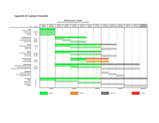
Timeline Update and Project Setbacks
Initial CAD designs with increased fidelity have been created for the legs and hips of RoBOT. The
actuator selection based on more detailed hand calculation of the torques required to raise and
lower the robot under the power of a single leg. Up until this point, a greater focus has been placed
on the leg/hip design and simulation over the central housing design, which is still in progress. At
the time of the Progress Report #1, the team expected to have the central housing design complete
by this progress report. However, an extra week has been allotted for this task since the team has
realized that its design is driven by the legs and hips and only serves to house the electronics of
RoBOT. This should be a fairly simple task that can be completed by next week. The simulation
section of the timeline has been updated to reflect the setback of the incompatibility of Siemens
NX and Simulink for co-simulation. The timeline now reflects the pivot to more detailed
simulation all within Simulink and the creation of a modified framework to support that simulation.
Another update to the timeline is a section to plan for the Oral Presentation, including a rehearsal
with Dr. Staelens on October 19th
and a final delivery on October 26th
.
Future Work
The major focus over the next three weeks will be to finalize the CAD models of the central
housing, hips, and legs. A complete CAD model should be ready to go for the last progress report.
The MATLAB simulation shown above opens a series of doors for optimization of controls,
electromechanical systems, and even geometry. Future work for the MATLAB simulation also
will center around finding our power and torque margins based on our chosen actuators, and set
minimum torque values determined earlier in this report.
The CAD for the two-leg links has been carefully parametrized in order to allow for this
functionality. The first result from the simulation is that the tendency of a high inertia leg to cause
the entire robot to yaw is extremely detrimental to performance, and that every effort must be made
to reduce the mass of components placed low on the leg. Outside of the Simulink model, further](https://image.slidesharecdn.com/progressreport2-201016075730/85/Bipedal-Robot-PDR-8-320.jpg)
![mechanical analysis will also be done to verify that all loads can be supported by the linkages and
pins in RoBOT. Finite Element Analysis will be conducted on linkages and shear calculations will
be performed on pins. This analysis will drive some of the final decisions such as material choice.
As these goals are worked towards, the team will also begin to prepare for the oral presentation,
which is on October 26th
. The team will start to create slides next week to have ready for a rehearsal
with Dr. Staelens on October 19th
.
References
[1] S. Kajita, F. Kanehiro, K. Kaneko, K. Yokoi and H. Hirukawa, "The 3D linear inverted
pendulum mode: a simple modeling for a biped walking pattern generation," Proceedings 2001
IEEE/RSJ International Conference on Intelligent Robots and Systems. Expanding the Societal
Role of Robotics in the Next Millennium (Cat. No.01CH37180), Maui, HI, USA, 2001, pp. 239-
246 vol.1.
[2] MathWorks Student Competitions Team (2020). MATLAB and Simulink Robotics Arena:
Walking Robot (https://github.com/mathworks-robotics/msra-walking-robot), GitHub.
Retrieved September 17, 2020.
[3]BajramiXh.,etal.”Kinematics and dynamics modelling of the biped robot.” IFAC Proceedings
Volumes 46.8,69-73,2013](https://image.slidesharecdn.com/progressreport2-201016075730/85/Bipedal-Robot-PDR-9-320.jpg)


This progress report details significant advancements in the design of a low-cost humanoid robotic testbed, focusing on high-fidelity CAD models of the robot's hips and legs, and updates on actuator selection. The team resolved mechanical power transmission issues by opting for belt and pulley systems and successfully created a functional MATLAB model for robot locomotion. Future work aims to finalize CAD models, optimize MATLAB simulations, and prepare for an upcoming oral presentation.


![ceramic-art-and-pottery [Autosaved].pptx](https://cdn.slidesharecdn.com/ss_thumbnails/ceramic-art-and-potteryautosaved-260113113456-35c55ddb-thumbnail.jpg?width=640&height=640&fit=bounds)


