Download to read offline
![6 International Journal for Modern Trends in Science and Technology
Volume: 2 | Issue: 05 | May 2016 | ISSN: 2455-3778IJMTST
ANFIS Based UPQC for Power Quality
Improvement
M. Sudhakar Babu1
| S. Rajasekhar2
1PG Scholar, Department of EEE, ASR College of Engineering and Technology, JNTUK, Andhra Pradesh.
2Assistant Professor, Department of EEE, ASR College of Engineering and Technology, JNTUK, Andhra
Pradesh.
Pa
Analysis of a three-phase three wire Unified Power Quality Conditioner (UPQC) controlled with Adaptive
Neuro Fuzzy Inference System based controller is presented in this project. UPQC is a custom power device
which is integrated by series and shunt active power filters (APF) sharing a common dc bus capacitor.
The shunt and series APFs are realized with the help of three – phase, three leg voltage source converters that
are sharing a common DC capacitor. The fundamental voltages, currents are extracted by modified
synchronous reference frame technique; switching pulses for both the filters are generated by conventional
hysteresis based controller. The capacitance voltage is balanced by ANFIS based controller. Performance of
the ANFIS based control algorithm of shunt active filter with series active filter is evaluated in terms of
eliminating the power quality problems in a three phase, three-wire distribution system with non-linear
and unbalanced load conditions. Adaptive neuro fuzzy logic control is used for dc capacitance balancing.
System taken for test and the control algorithm are implemented with the help of Sim power systems and
ANFIS editor of MATLAB / SIMULINK.
KEYWORDS: Non Linear Load,UPQC, Compensation, ANFIS Control
Copyright © 2015 International Journal for Modern Trends in Science and Technology
All rights reserved.
1. INTRODUCTION
PQ studies have emerged as a significant topic
because of the extensive use of sensitive electronic
equipments. A broad definition of power quality
that includes the definitions of technical quality
and supply continuity states that the limits
specified in the standards and regulations should
not be exceeded by electrical PQ or in other words
frequency, number and interval of interruption,
interruption in voltage, sine waveform and voltage
unbalance . Nowadays power quality is definitely a
big issue and the inclusion of advanced devices,
whose functioning is extremely sensitive to the
quality of power supply, makes it especially
important. Due to the increasing anxiety over
supplying pure electrical energy to the consumers
in the availability of non sinusoidal waveforms, PQ
has gained much interest in recent years.
The basic requirements for compensation
process involve precise and continuous VAR
control with fast dynamic response and on-line
elimination of load harmonics. To satisfy these
criterion, the traditional methods of VAR
compensation using switched capacitor and
thyristor controlled inductor coupled with passive
filters are increasingly replaced by active power
filters (APFs). The APFs are of two types; the shunt
APF and the series APF.
The shunt APFs are used to compensate current
related problems, such as reactive power
compensation, current harmonic filtering, load
unbalance compensation, etc. The series APFs are
used to compensate voltage related problems, such
as voltage harmonics, voltage sag, voltage swell,
voltage flicker, etc. The unified power quality
conditioner (UPQC) aims at integrating both shunt
and series APFs through a common DC link
capacitor. The UPQC is similar in construction to a
unified power flow controller (UPFC) [9]. The UPFC
is employed in power transmission system,
whereas the UPQC is employed in a power
distribution system. The primary objective of UPFC
is to control the flow of power at, fundamental
ABSTRACT](https://image.slidesharecdn.com/38-160517111641/85/ANFIS-Based-UPQC-for-Power-Quality-Improvement-1-320.jpg)
![6 International Journal for Modern Trends in Science and Technology
Volume: 2 | Issue: 05 | May 2016 | ISSN: 2455-3778IJMTST
ANFIS Based UPQC for Power Quality
Improvement
M. Sudhakar Babu1
| S. Rajasekhar2
1PG Scholar, Department of EEE, ASR College of Engineering and Technology, JNTUK, Andhra Pradesh.
2Assistant Professor, Department of EEE, ASR College of Engineering and Technology, JNTUK, Andhra
Pradesh.
Pa
Analysis of a three-phase three wire Unified Power Quality Conditioner (UPQC) controlled with Adaptive
Neuro Fuzzy Inference System based controller is presented in this project. UPQC is a custom power device
which is integrated by series and shunt active power filters (APF) sharing a common dc bus capacitor.
The shunt and series APFs are realized with the help of three – phase, three leg voltage source converters that
are sharing a common DC capacitor. The fundamental voltages, currents are extracted by modified
synchronous reference frame technique; switching pulses for both the filters are generated by conventional
hysteresis based controller. The capacitance voltage is balanced by ANFIS based controller. Performance of
the ANFIS based control algorithm of shunt active filter with series active filter is evaluated in terms of
eliminating the power quality problems in a three phase, three-wire distribution system with non-linear
and unbalanced load conditions. Adaptive neuro fuzzy logic control is used for dc capacitance balancing.
System taken for test and the control algorithm are implemented with the help of Sim power systems and
ANFIS editor of MATLAB / SIMULINK.
KEYWORDS: Non Linear Load,UPQC, Compensation, ANFIS Control
Copyright © 2015 International Journal for Modern Trends in Science and Technology
All rights reserved.
1. INTRODUCTION
PQ studies have emerged as a significant topic
because of the extensive use of sensitive electronic
equipments. A broad definition of power quality
that includes the definitions of technical quality
and supply continuity states that the limits
specified in the standards and regulations should
not be exceeded by electrical PQ or in other words
frequency, number and interval of interruption,
interruption in voltage, sine waveform and voltage
unbalance . Nowadays power quality is definitely a
big issue and the inclusion of advanced devices,
whose functioning is extremely sensitive to the
quality of power supply, makes it especially
important. Due to the increasing anxiety over
supplying pure electrical energy to the consumers
in the availability of non sinusoidal waveforms, PQ
has gained much interest in recent years.
The basic requirements for compensation
process involve precise and continuous VAR
control with fast dynamic response and on-line
elimination of load harmonics. To satisfy these
criterion, the traditional methods of VAR
compensation using switched capacitor and
thyristor controlled inductor coupled with passive
filters are increasingly replaced by active power
filters (APFs). The APFs are of two types; the shunt
APF and the series APF.
The shunt APFs are used to compensate current
related problems, such as reactive power
compensation, current harmonic filtering, load
unbalance compensation, etc. The series APFs are
used to compensate voltage related problems, such
as voltage harmonics, voltage sag, voltage swell,
voltage flicker, etc. The unified power quality
conditioner (UPQC) aims at integrating both shunt
and series APFs through a common DC link
capacitor. The UPQC is similar in construction to a
unified power flow controller (UPFC) [9]. The UPFC
is employed in power transmission system,
whereas the UPQC is employed in a power
distribution system. The primary objective of UPFC
is to control the flow of power at, fundamental
ABSTRACT](https://image.slidesharecdn.com/38-160517111641/75/ANFIS-Based-UPQC-for-Power-Quality-Improvement-1-2048.jpg)
![9 International Journal for Modern Trends in Science and Technology
ANFIS Based UPQC for Power Quality Improvement
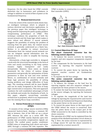
5. SIMULATION RESULTS
The model for UPQC control using ANFIS method
has been successfully modeled and tested using
MATLAB/SIMULINK toolbox. The performance in
steady state condition is evaluated using FFT
simulation.
Fig 4: Simulation model of ANFIS based UPQC
Fig 5: Simulation model of UPQC control
Figure 4: Simulation model of ANFIS control
Figure 5: waveform for V injected, load voltage, source
voltage
Figure 6: waveform for I injected, load current, source
current
Figure 7: waveform for DC link voltage
6. CONCLUSION
Different power harmonic sources exist mainly
due to nonlinear loads made up of power
electronics devices. In this paper, an ANFIS based
UPQC controller was proposed for compensating
the PQ problem. The proposed controller was
implemented using MATLAB/SIMULINK. Proposed
controller can achieve a better performance of PQ
issues compared with the FLC, NFC and NN based
controllers.
REFERENCES
[1] Gyugyi L., “Reactive power generation and control by
thyristor circuits,” IEEE Trans. Ind. Appl., vol. 15,
no. 5, pp. 521-532, 1979.
[2] Jin H., Goós G. and Lopes L., “An efficient
switched-reactor-based static var compensator,”
IEEE Trans. Ind. Appl., vol. 30, no. 4, pp. 998-1005,
1994.
[3] Mahanty R., “Large value AC capacitor for harmonic
filtering and reactive power compensation,” IET Gen.
Transm. Distrib., vol. 2, no. 6, pp. 876-891, 2008.
[4] Hirve S., Chatterjee K., Fernandes B. G.,
Imayavaramban M. and Dwari S., “PLL-less active
power filter based on one-cycle control for
compensating unbalanced loads in three-phase
four-wire system,” IEEE Trans. Power Deliv., vol. 22,
no.4, pp. 2457-2465, 2007.
[5] Lascu C., Asiminoaei L., Boldea I. and Blaabjerg F.,
“High performance current controller for selective
harmonic compensation in active power filters,”
IEEE Trans. Power Electron., vol. 22, no. 5, pp.
1826- 1835, 2007.](https://image.slidesharecdn.com/38-160517111641/85/ANFIS-Based-UPQC-for-Power-Quality-Improvement-4-320.jpg)
![10 International Journal for Modern Trends in Science and Technology
Volume: 2 | Issue: 05 | May 2016 | ISSN: 2455-3778IJMTST
[6] Gyugi L., “Unified power-flow control concept for
flexible AC transmission systems,” IEE Proc. C
Gener. Transm. Distrib., vol. 139, no. 4, pp.
323-331, 1992.](https://image.slidesharecdn.com/38-160517111641/85/ANFIS-Based-UPQC-for-Power-Quality-Improvement-5-320.jpg)

The document presents a study on an Adaptive Neuro-Fuzzy Inference System (ANFIS) based Unified Power Quality Conditioner (UPQC) aimed at improving power quality in three-phase systems with non-linear loads. The UPQC integrates shunt and series active power filters to manage voltage and current distortions, and the ANFIS enhances system performance by optimizing the control of DC link capacitance. Simulation results indicate that the ANFIS-based controller outperforms traditional methods in addressing power quality issues.