UNIT 4
AIRCONDITIONING ANDPRESSURIZING
SYSTEM
Prepared By
M.Sasi Kumar
AP/AERO
KIT-Kalaignarkarunanidhi Institute of Technology, Coimbatore
2.
Aircraft air conditioningsystem
• Aircraft-cooling systems, also called air-conditioning
systems, are used to reduce the temperature inside an
aircraft for crew and passenger comfort
• Types
• vapor-cycle machine
• air-cycle machine
3.
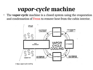
vapor-cycle machine
• Thevapor-cycle machine is a closed system using the evaporation
and condensation of Freon to remove heat from the cabin interior.
4.
Vapor-Cycle Cooling Systems
•The vapor-cycle air-conditioning system is used in
reciprocating engine powered aircraft and in smaller
turboprop aircraft.
• The operation of vapor-cycle machines is controlled by the
pilot and may incorporate automatic cutout or interrupt
systems.
• These cutout and interrupt systems are used to disengage the
refrigerant compressor during demand for high engine power
output
5.
Conti..
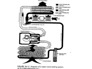
• A vapor-cyclecooling system using two heat-exchangers to
control the temperature of the cockpit and cabin.
• The one heat exchanger draws heat from the air and adds it
to the closed system. This heat exchanger is called a
condenser. The Another heat exchanger taking heat from the
closed system, and is called an evaporator.
• Instead of water in the heat exchanger, a special fluid called a
refrigerant is used. The refrigerant, usually Freon, takes two
forms during the cooling process, liquid and gas
7.
Conti..
• The coolingprocess starts at the compressor, where
the refrigerant is in a gaseous form. The function of
the compressor is to push the refrigerant, under
pressure, through the entire system.
• As the gas enters the condenser, heat is drawn from
the refrigerant and passed to the atmosphere. The
cooling of the refrigerant causes it to condense into a
liquid. Because of the compressor, the liquid is under
pressure.
8.
Conti..
• The pressurizedliquid is then metered into tiny
droplets by an expansion valve.
• The droplets then enter the evaporator, where they
draw heat from the air and then change into a gas.
• As a result of heat being drawn from the air, the
temperature of the air is decreased. It is this cooler
air that is introduced to the cabin for cooling
9.
Air-Cycle Cooling
• Modernlarge turbine powered aircraft make use of air-cycle
machines to adjust the temperature of the air directed into
the passenger and crew compartments of these large aircraft.
• the cabin can also be heated and pressurized by the use of an
air-cycle machine
• These large aircraft utilize air-cycle cooling because of its
simplicity, freedom from troubles.
10.
Conti..
• Refrigerant used– Air.
• The principle of cooling by means of a gas is simple. When a
gas (air) is compressed, it becomes heated, and when the
pressure is reduced, the gas becomes cooled.
• If a pressure cylinder is connected to an air compressor and
compressed air is forced into the cylinder, one can observe
that the cylinder becomes warm or even hot, depending upon
the level of compression and the rate at which the air is
compressed.
11.
Conti..
• If thecylinder filled with highly compressed air is then
allowed to cool to ambient temperature, the pressure in the
cylinder will be reduced to a certain degree as the air
temperature is reduced.
• If a valve is then opened and the air is allowed to escape from
the cylinder, the temperature of the escaping air will be much
lower than the ambient temperature due to the air expanding
as its pressure returns to the ambient value. This cold air can
then be used as a cooling agent.
• In an air-cycle system, the air is continuously compressed
and then cooled by means of heat exchangers through which
ram air is passed; then the pressure is reduced by passing the
air through an expansion turbine
13.
Conti..
• The airleaving the expansion turbine is at low pressure and
low temperature. The cooled air is directed through ducting
with control valves to regulate the amount of cooling air
needed to produce the desired cabin temperature.
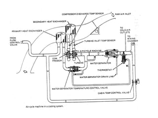
• The turbine-compressor unit by which air is cooled is called
an air-cycle machine (ACM).
• Hot compressed air from the compressor of one of the turbine
engines flows through the primary heat exchanger. The heat
exchanger is exposed to ram air, which removes heat from the
air.
14.
Conti..
• The cooledbut still compressed air is then ducted to the
compressor inlet of the ACM. The compressor further
compresses the air and causes it to rise in temperature. This
air is directed to the secondary heat exchanger, which, being
exposed to ram air, removes heat from the compressed air.
• The compressed air is then directed to the expansion turbine.
The expansion turbine absorbs energy from the air and
utilizes this energy to drive the compressor.
• As the air exits the expansion turbine, it enters a large
chamber, which allows the air to expand and causes a further
reduction in the air temperature.
15.
Conti..
• Thus theair leaving the turbine is cooled by the loss of heat
energy and by the expansion that takes place. The great
reduction in temperature causes the moisture in the air to
condense, and this moisture is removed by means of a water
separator.
• The dried, cold air is then routed to ducting to be utilized as
required to provide the desired temperature in the cabin.
16.
AIR CONDITIONING SYSTEM
MAINTENANCE
•Procedure depends on the particular aircraft model
• Maintenance and manufacturer manual must be referred for
correct procedure
• It is consists of inspections, servicing, removing, and
installing components, performing operational checks, and
troubleshooting for the isolation and correction of troubles
within the system
17.
Inspections
• Periodically inspectthe system for component security and
visible defects.
• Particular attention should be paid to the heat exchangers for
signs of structural fatigue adjacent to welds
• The ducting should be securely attached and adequately
supported.
• Insulating blankets must be in good repair and secured
around the ducting.
18.
Servicing
• Each refrigerationunit contains Freon for absorbing heat, plus
oil mixed with the Freon for lubricating the compressor motor
bearings.
• insufficient Freon system incapable of absorbing heat.
• insufficient oil, the motor bearings will overheat and cause
unsatisfactory compressor operation.
• System Freon loop contains quantities of both liquid and vapor.
So it is unpredictable exactly where in the system the liquid
will be at any one instant makes it difficult to check the
quantity of Freon in the system.
• a standard set of conditions should be obtained when checking
the Freon level. These conditions are specified by the
manufacturer
19.
Conti..
• To checkthe Freon level, it is necessary to operate the
refrigeration unit for approximately 5 min to reach a stable
condition
• If the system uses a sight glass, observe the flow of Freon
through the sight glass. A steady flow indicates that a
sufficient charge is present If the Freon charge is low, bubbles
will appear in the sight glass.
• When adding Freon to a system, add as much oil as is felt was
lost with the Freon being replaced. It is impossible to
determine accurately the amount of oil left in a Freon system
after partial or complete loss of the Freon charge
20.
Conti..
• Usually one-fourth-onceof oil is added for each pound of
Freon added to the system
• The oil used is a special highly refined mineral oil free from
wax, water and sulfur. Always use the oil specified in the
manufacturer's maintenance manual for a specific system.