The document provides operating instructions for the AG-HPX500P/E P2 memory card camera-recorder, which features a 2/3-inch lens mount, support for multiple HD and SD formats including variable frame rates, 4 P2 card slots for extended recording, and menus for adjusting settings like white balance, shutter speed, and audio levels.


![Parts and their
Chapter 2 Functions
Power Supply and Accessory Mounting Section
Chapter 2 Parts and their Functions
5 13 2 5 6 14 7 8
1 4 3 15 10 12 11 9
1 POWER switch 11 Tripod mount
Used to turn on/off the power. When you want to mount the AG-HPX500P/E
2 Battery mount on a tripod, the optional tripod adapter (SHAN-
A battery pack from Anton/Bauer is mounted TM700) is attached here.
here. 12 LENS jack (12-pin)
3 DC IN (external power input) socket (XLR, The lens connection cord is connected here.
4P) For a detailed description of your lens, see the
This unit is connected to an external DC power relevant manufacturer’s instruction manual.
supply (DC12 V). 13 Release lever
4 BREAKER switch Pull down the release lever to release the battery
When an excessive amount of current is fed pack.
through the video camera-recorder, due to any 14 Viewfinder left-right positioning ring
abnormal event, the breaker automatically turns For details, see [Adjusting Viewfinder Right-Left
off the power in order to protect the device. Position].
After the interior of the video camera-recorder 15 Light control switch
has been checked and/or repaired, this button For details, refer to [Power Supply].
must be depressed. If there is no unusual
reaction, the unit can be powered-up.
5 Light shoe
A video light or similar accessory can be attached
here.
6 Shoulder strap fittings
The shoulder strap is attached here.
7 Lens mount (bayonet type)
The lens is attached here.
8 Lens lever
Lower this lever to lock the lens to the lens mount.
9 Lens mount cap
To remove the cap, raise the lens lever.
When the lens is not mounted, replace the cap.
10 Lens cable/microphone cable clamp
This clamp secures the lens and microphone
cables.
15](https://image.slidesharecdn.com/ag-hpx500emanual-100120045233-phpapp01/85/Ag-Hpx500-E-Manual-15-320.jpg)
![Audio (input) Function Section
Chapter 2 Parts and their Functions
9 8 2 3 7
1 4 5 6
1 MIC IN (microphone input) jacks 4 AUDIO LEVEL CH3/CH 4 (audio channel 3
FRONT1/FRONT2 (XLR, 3-pin) & 4 recording level adjustment) controls
Connect microphones (optional accessories) to Set the menu option AUTO LEVEL CH3/AUTO
these jacks. Power for the microphone comes LEVEL CH4 to OFF in the <AUDIO SETUP>
from this jack. screen to use these controls to adjust the
A phantom-powered microphone may be recording level of audio channels 3 and 4.
connected. To use a phantom-powered 5 AUDIO IN (audio input selector) switch
microphone, set the menu option F.MIC Use this switch to select the signals recorded
POWER1/F.MIC POWER2 to ON in the <AUDIO through Audio Channels 1 - 4.
SETUP> screen. FRONT: Signal from the microphone connected
2 AUDIO LEVEL CH1/CH2 (audio channel 1 to the MIC IN jack is recorded.
& 2 recording level adjustment) controls REAR: Signal from the audio device connected
With the AUDIO SELECT CH1/CH2 switch to the REAR 1/REAR 2 connector is
positioned to [MAN], these controls can be used recorded.
to adjust the recording levels for Audio Channels CH1 Input CH2 Input
1/2. FRONT1 FRONT1 jack FRONT FRONT2 jack
Note that the controls are designed to be locked. FRONT2 FRONT2 jack REAR REAR2 jack
For adjustment, each control must be depressed REAR REAR1 jack — —
while turning. CH2 Input CH4 Input
3 AUDIO SELECT CH1/CH2 (audio channel FRONT FRONT1 jack FRONT FRONT2 jack
REAR REAR1 jack REAR REAR2 jack
1 & 2 automatic/manual level adjustment
selector) switch 6 REAR 1/REAR 2 (audio input channel 1 &
Use this switch to select recording level control 2) connectors (XLR, 3-pin)
mode for Audio Channels 1 and 2. Audio devices or a microphone may be
AUTO: Recording level automatically controlled. connected here.
MAN: Recording level manually controlled.
16](https://image.slidesharecdn.com/ag-hpx500emanual-100120045233-phpapp01/85/Ag-Hpx500-E-Manual-16-320.jpg)


![Shooting and Recording/Playback Functions Section
Chapter 2 Parts and their Functions
1 8 2
9
3 4 5 6 7
Shooting and Recording (camera unit) 4 AUTO W/B (white/black) BAL switch
1 ND FILTER (filter switching) control Automatically adjusts the white balance.
This control adjusts the amount of light entering Set the WHITE BAL switch on the side to
the CCD. Use this control in strong outdoor [A] or [B] and use this switch to adjust the
white balance, which takes a few seconds.
lighting. AWB
The adjusted value is stored in memory.
Control Note that auto white balance adjustment is
Setting Description
position not available when the WHITE BAL switch
1 OFF Do not use the ND filter.
is set to [PRST].
Reduces the amount of light
2 1/4 ABB Back balance is automatically adjusted.
entering the CCD to 1/4.
Reduces the amount of light
3 1/16
entering the CCD to 1/16.
5 GAIN selector switch
Reduces the amount of light This switch adjusts video amplifier gain to suit
4 1/64 ambient lighting conditions at the time of the
entering the CCD to 1/64.
shooting.
2 USER MAIN, USER 1 and USER 2 buttons Use the menu options MID GAIN and HIGH
These buttons can be assigned user-selected GAIN in the <SW MODE> screen to set the M/H
functions, using a menu option. Each button, position gain values.
when pressed, performs the assigned function. The factory settings for L, M and H are 0 dB,
For more information, see [Assigning Functions to 6 dB, and 12 dB, respectively.
USER MAIN, USER1 and USER2 Buttons]. <Note>
3 SHUTTER switch The camera is locked to 0 dB gain regardless of
Used to enable or disable the electronic shutter. GAIN switch position and setting when the FRAME
OFF: Electronic shutter disabled. RATE is 22 fps (59.94 Hz) or less than 23 fps (50 Hz)
ON: Electronic shutter enabled. and the slow shutter is set to 1/15 (59.94 Hz) or 1/12
SEL: Used to change the speed of the electronic (50 Hz/59.94 Hz).
shutter.
This dial switch returns to its original position.
Each turn of the switch alters the shutter speed.
For more information, see [Setting the Electronic
Shutter].
19](https://image.slidesharecdn.com/ag-hpx500emanual-100120045233-phpapp01/85/Ag-Hpx500-E-Manual-19-320.jpg)
![6 OUTPUT/AUTO KNEE selector switch 9 MODE button
This switch selects the video signals sent from This button toggles between the CAMERA mode
the camera unit to the memory card recorder unit, and MCR mode at each press.
viewfinder and video monitor. Holding down this button for 2 seconds or longer
Chapter 2 Parts and their Functions
Video being recorded through the camera in the MCR mode will engage the PC mode.
CAM. is output with the AUTO KNEE circuit Since this button does not work in the PC mode,
AUTO activated. The compression level (KNEE power off the camera to exit the PC mode and
KNEE ON point) of the video signal is automatically switch to another mode. The camera will start
changed according to the received signal. up in the CAMERA mode when powered up next
Video being recorded through the camera
CAM. time.
is output with the AUTO KNEE circuit
AUTO Use the mode LED (Page XX) to check current
turned off. The KNEE point is locked to
KNEE OFF mode.
the level set in the menu.
Color bar signals are output with the
BARS
AUTO KNEE circuit turned off.
<Note>
This switch does not work in the MCR mode.
■AUTO KNEE function
Usually, when you adjust levels to shoot people
or scenery against a strongly lit background,
the background will be totally whited-out, with
buildings and other objects blurred.
In this case, the AUTO KNEE function reproduces
the background clearly.
This function is effective when:
• The subject is a person positioned in the shade
under a clear sky.
• The subject is a person inside a car or building,
and you also want to capture the background
visible through a window.
• The subject is a high-contrast scene.
7 WHITE BAL (white balance memory
selector) switch
Used to select the white balance adjustment
method.
PRST: Use this when you have no time to adjust
the white balance.
• The value for the white balance is
factory-set to 3200 K.
• It can be changed to any color
temperature using a menu option. For
more information, see [Setting Color
Temperature Manually].
A or B: Pressing the AUTO W/B BAL Switch
toward [AWB] automatically adjusts the
white balance, saving the adjusted value
in Memory A or B. For more information,
see [Adjusting the White Balance].
8 DISP/MODE CHECK button
Press this button to turn off the LCD monitor and
viewfinder display. (The time code indication
stays on.)
A second press of the button turns the display
back on and holding it down displays shooting
conditions and functions assigned to USER
switches.
It also serves to turn off the alarm sound.
20](https://image.slidesharecdn.com/ag-hpx500emanual-100120045233-phpapp01/85/Ag-Hpx500-E-Manual-20-320.jpg)

![Shooting and Recording/Playback 21 USB 2.0 connector
Function Section (recording) Connect a USB 2.0 cable to this connector.
Select USB DEVICE under the menu option PC
10 REC START/STOP button
MODE in the <OTHER FUNCTIONS> screen to
Pressing this button starts recording, pressing
Chapter 2 Parts and their Functions
send data via the USB 2.0 connector. The camera
again stops recording.
cannot be used for recording, playback or clip
This button has the same function as the REC
operations when this function is used. For details,
button on the handle and the VTR button at the
see [Connecting to External Devices Using
lens.
USB2.0 Port].
When pressed in the MCR mode, the camera
22 GENLOCK IN connector
automatically switches to the CAMERA mode and
This connector inputs a reference signal when the
starts recording.
camera unit is gen-locked, or when the time code
11 SAVE switch
is externally locked.
This switch selects the power saving mode. <Note>
ON: Forcibly turns off the LCD. The reference input signal must be an HD3 SYNC
OFF: LCD is on. (at 1080/60i, 720/60p, 1080/50i or 720/50p) or an
The operating status display goes off when the SD2 SYNC (at 480/60i or 576/50i).
SAVE switch is set to ON. 23 REMOTE (remote control) connector
But it remains on during special recording. The extension control unit AJ-RC10G (optional
12 OUT PUT CHARACTER switch accessory) is connected here.
This switch controls the superimposition of 24 VIDEO OUT (video signal output)
characters onto the video output (VIDEO OUT, connector
COMPONENT OUT and SDI OUT) from the This connector outputs video signals. The video
VIDEO OUT connector to indicate status or signals linked to the setting of the OUTPUT SEL
menus. switch are output from here.
ON: Superimposes characters. 25 SD memory card insertion slot
OFF: Does not superimpose characters. Insert an SD memory card (optional accessory) in
13 REW (fast-reverse) button this slot. It is used for uploading meta data as well
During pause, this button performs fast-reverse as for reading and writing USER files and SCENE
playback. (MCR mode) files.
During playback, it fast-reverses playback at <Note>
about 4× normal speed. ■SD memory card precautions
If this button is pressed when playback is paused, • Use only cards that conform to the SD card
the beginning of the clip being played is located in standard or the SDHC standard in this camera.
pause mode (cue-up mode). • Multimedia cards cannot be used. (Use of such
cards may prevent recording.)
14 FF (fast forward) button
• Be sure to use mini SD and mini SDHC card
During pause, this button performs fast playback.
adapters only when using mini SD and mini SDHC
(MCR mode) cards. Note that this camera will not operate
During playback, it performs fast playback at normally when a mini SD or mini SDHC adapter is
about 4× normal speed. installed without also inserting a card. Be sure to
If this button is pressed when playback is paused, insert a card when an adapter is installed.)
the beginning of the next clip is located in pause • Use of Panasonic SD memory cards and mini
mode (cue-up mode). SD/mini SDHC cards is recommended. Be sure to
15 ■STOP button format such cards in this camera.
• To format a memory card on a PC, use the
This button stops playback. (MCR mode)
following software that can be downloaded from
The menu cursor moves in the thumbnail display.
the support site listed below.
16 PLAY button https://eww.pavc.panasonic.co.jp/pro-av/
This button is used to view playback using the • This camera supports 8 MB, 16 MB, 32 MB, 64 MB,
viewfinder screen or a color video monitor. (MCR 128 MB, 256 MB, 512 MB, 1 GB and 2 GB SD
mode) memory cards and 4 GB SDHC memory cards.
17 STILL (pause) button • For the latest information not available in the
Press to pause playback. (MCR mode) Operating Instructions, visit the P2 Support site at
the above Web site.
18 REC buttons (red and white)
■About SD and SDHC memory cards
Press the red and white buttons simultaneously • SD logo is a trademark.
to start recording the 1394 input signal and press • The SDHC (SD High Capacity) card is a new
the STOP button to stop recording. This function standard, established by the SD Card Association
is available only in the MCR mode. in 2006, for large-scale memory cards with
19 P2 CARD ACCESS LED capacities above 2 GB.
This LED indicates the recording and playback • Multi Media Card (MMC) is a registered trademark
status of each card. of Infineon Technologies AG.
20 Slide lock button
Used to open the slide-out door for inserting P2
cards. While depressing this button, slide the
door to the left.
22](https://image.slidesharecdn.com/ag-hpx500emanual-100120045233-phpapp01/85/Ag-Hpx500-E-Manual-22-320.jpg)
![26 BUSY (operation mode display) lamp
This lamp indicates the active status of the SD
memory card.
It stays illuminated when the card is active.
Chapter 2 Parts and their Functions
<Note>
While the lamp is on, do not insert or remove the
card.
27 R-SIDE P2 card access LED
This LED indicates access status for all four P2
card slots. It blinks when any of the inserted
P2 cards is accessed and lights when a card is
inserted.
28 COMPONENT OUT connector (D4
connector)
This connector outputs component video signals.
Use the menu option CMPNT/SDI SEL in the
setting menu <OUTPUT SEL> screen to select
720P, 1080i, 480i, or 576i. This connector does
not support up-conversion.
29 1394 connector
Connect an IEEE1394 cable to this connector.
Select 1394 DEVICE or 1394 HOST under
the menu option PC MODE in the <OTHER
FUNCTIONS> screen to send data via the
1394 connector. For details, see [Connecting to
External Devices Using USB2.0 Port].
30 SDI OUT connector
This connector outputs SDI signals.
Use the menu option CMPNT/SDI SEL in the
setting menu <OUTPUT SEL> screen to select
720P, 1080i, 480i, or 576i. This connector does
not support up-conversion.
31 SCENE FILE dial
This dial allows you to load and set the shooting
conditions for a scene file already recorded with
the conditions corresponding to the dial position.
<Note>
During recording, selecting a position with a
different frame rate will not change the frame rate
until the camera is set to recording standby mode.
32 PAGE/VAR button
In the thumbnail display, press this button to turn
pages; during variable speed playback press it to
change playback speed and in still mode, press it
to start frame-by-frame playback.
33 FOCUS ASSIST button
This button turns focus assist on and off.
Turning on the focus assist function displays
a frequency distribution graph in the top right
corner of the viewfinder and LCD display.
Turn the focus ring on the lens to place the graph
further to the right.
When the image is out of The white area moves
focus to the right as the image
comes into focus.
23](https://image.slidesharecdn.com/ag-hpx500emanual-100120045233-phpapp01/85/Ag-Hpx500-E-Manual-23-320.jpg)
![Menu Operation Section
Chapter 2 Parts and their Functions
6 1
5 2
3 4
1 MENU button 6 JOG dial button
Press this button to display the setting menu and Use this button to go between menu pages and
press it again to return to the previous image. to select and set items in open setting menus
This button is not available in the thumbnail (camera menu or MCR menu).
display. In a setting menu, turning the JOG dial
<NOTE> downwards moves the menu cursor downwards
Use the SET button or the JOG dial button to go and turning it upwards moves the menu cursor
between menus and select items. For details, see upwards.
section [Viewfinder and LCD menus]. Press the JOG dial button to confirm made
2 Thumbnail button settings.
In MCR mode, press this button to open the
thumbnail screen.
Note that this switchover is not performed during
recording or playback.
3 Thumbnail menu button
In thumbnail display mode, use this button to
access thumbnail menu functions to delete clips,
for example.
Pressing this button when thumbnail is not shown
in camera mode or MCR mode displays the
camera menu or MCR menu.
<Note>
Use the CURSOR and SET buttons to select
thumbnails and access menu functions. For details,
see [Manipulating Clips with Thumbnails].
4 CURSOR and SET buttons
Use these buttons to manipulate menus, the
menu bar and thumbnails.
The four triangular buttons are CURSOR buttons
and the square center button is the SET button.
5 PAGE/VAR button
Pressing this button during thumbnail display
scrolls thumbnail pages forwards and backwards
in page units.
24](https://image.slidesharecdn.com/ag-hpx500emanual-100120045233-phpapp01/85/Ag-Hpx500-E-Manual-24-320.jpg)
![Time Code Section
Chapter 2 Parts and their Functions
2 4 6 5
1 3 7 8
1 GENLOCK IN connector (BNC) 6 COUNTER (counter display selector)
This connector is used to input a reference signal button
before the camera unit is gen-locked, or before The LCD monitor and the viewfinder show the
the time code is externally locked. counter value, time code, user bit and frame rate
2 TC IN connector (BNC) data depending on how this switch and the TCG
This connector is used to input a reference time switch are set.
code when you externally lock the time code. 7 TCG (time code selector) switch
3 TC OUT connector (BNC) This switch is used to specify the stepping mode
When you inter-lock the time code of the AG- for the built-in time code generator.
HPX500P/E with that of an external device this Select this position to continuously
must be connected with the time code input (TC advance the time code independently of
IN) connector of the external device. the P2 card recording status. Use this
F-RUN
4 HOLD button mode to synchronise the time code with
the time of day, or to externally lock the
Pressing this button freezes the time data
time code.
indication on the counter. Note that time code Select this position to set the time code
generation continues. Pressing the button again SET
and/or user bits.
reactivates the counter. Select this position to advance the time
This function is used to ascertain the time code or code only during recording. The time code
CTL count of a particular recorded scene. is continuously recorded during normal
5 RESET button recording. But deleting clips and continue
R-RUN
Use this button to reset the counter value on the recording of clips at a frame rate of 24P
or 24PA that have been recorded at any
time code display to 00:00:00.
other frame rate may break the sequence
When the TCG switch is positioned at [SET] and
of time code recording.
the setting menus TC PRESET screen and UB
PRESET screen are open, press this button to 8 CURSOR and SET buttons
reset all set values to 0 and press the SET button Use these buttons to set the time code and user
to preset. bits.
The four triangular buttons are the CURSOR
buttons, and the center rectangular one is the
SET button.
For guidance in setting the time code and user
bits, see [Setting Time Data].
25](https://image.slidesharecdn.com/ag-hpx500emanual-100120045233-phpapp01/85/Ag-Hpx500-E-Manual-25-320.jpg)
![Warning and Status Display LCD Monitor
Functions
Chapter 2 Parts and their Functions
1 2 3
1 2
5 4
1 LCD monitor
The LCD monitor displays the video in the
1 Back tally lamp viewfinder.
When the BACK TALLY switch is set to [ON], the Alternatively, it can show clips on the P2 card in a
lamp behaves in the same way as the front tally thumbnail format.
lamp at the viewfinder. In thumbnail display mode, you can use the
2 BACK TALLY switch thumbnail menu buttons, CURSOR and SET
This switch controls the action of the back and buttons to manipulate or delete clips, or format P2
rear tally lamps. cards.
ON: Back and rear tally lamps enabled. 2 OPEN button
OFF: Back and rear tally lamps disabled. Used to open the LCD monitor.
3 WARNING lamp
This lamp starts blinking or lights up if something
unusual occurs in the memory.
4 Rear tally lamp
When the BACK TALLY switch is set on [ON], the
rear tally lamp behaves in the same way as the
back tally lamp.
5 Mode LED
Shows the camera unit mode.
CAM: Lights in CAMERA mode.
MCR: Lights in MCR mode.
PC: Lights in PC mode.
26](https://image.slidesharecdn.com/ag-hpx500emanual-100120045233-phpapp01/85/Ag-Hpx500-E-Manual-26-320.jpg)
![Viewfinder
Chapter 2 Parts and their Functions
13 11 8 7 9 10
12
4 2 5 3 6 1
1 Viewfinder (supplied accessory) 7 Front tally lamp
During recording or playback, the viewfinder This lamp goes on during recording when
displays the video image in monochrome. It also the TALLY switch is set to [ON]. It also blinks
displays warnings, messages, zebra patterns, in synchronisation with the REC lamp in the
markers (safety zone and center markers), etc. viewfinder, and provides alerts.
2 ZEBRA (zebra pattern) switch 8 Viewfinder securing screw
This switch is used to display the zebra pattern in Used to attach or remove the viewfinder.
the viewfinder. 9 Eyepiece
ON: Zebra pattern displayed. 10 Diopter adjustment lever
OFF: No zebra pattern displayed. Use this to make adjustments in line with your
3 TALLY switch diopter, in order to obtain optimum clarity in the
Used to control the front tally lamp. viewfinder image.
ON: Tally lamp goes on. 11 Connecting plug
OFF: Tally lamp goes out. 12 Locking button
4 PEAKING control 13 Microphone holder
Used to adjust the outlines of the video image
in the viewfinder for easier focusing. Recorded
video and output camera signals are not affected.
5 CONTRAST control
Used to adjust the contrast of the video image
in the viewfinder. Recorded video and output
camera signals are not affected.
6 BRIGHT control
Used to adjust the brightness of the video image
in the viewfinder. Recorded video and output
camera signals are not affected.
27](https://image.slidesharecdn.com/ag-hpx500emanual-100120045233-phpapp01/85/Ag-Hpx500-E-Manual-27-320.jpg)

![P2 Cards
Chapter 3 Recording and Playback
Inserting P2 Cards
<Note>
When using the camera-recorder for the first time, be
3 Insert a P2 card in a P2 card slot.
• Press in the card until the eject button pops
sure to set the time data beforehand. On how the time up.
data is set, see [Setting Date and Time of Internal Clock]. EJECT button
1 Turn on the POWER switch.
2 While pressing the slide lock button,
move the slide-out door to the left.
• The door opens.
The card must be
inserted with the logo
right way up.
4 Tilt up the popped-up EJECT button.
P2 CARD ACCESS LED
Slide lock button
Slide-out door
5 Insert a P2 card into the AG-HPX500P/
E. The P2 CARD ACCESS LED for the
appropriate slot indicates the status of
the P2 card.
For how the P2 card status is indicated, see
[P2 CARD ACCESS LED and status of P2
cards].
30 P2 Cards](https://image.slidesharecdn.com/ag-hpx500emanual-100120045233-phpapp01/85/Ag-Hpx500-E-Manual-30-320.jpg)
![6 Close the slide-out door. 3 Then depress the eject button to
release the P2 card.
<Note>
Chapter 3 Recording and Playback
• To prevent cards from falling out, dust from entering
and reduce the risk of exposure to static electricity, do
not move the AG-HPX500/PE with the slide-out door
open.
• Format P2 cards on a P2 device or on a PC using P2
Viewer software (Ver.000 or later).
Removing P2 Cards
1 While pressing the slide lock button,
move the slide-out door to the left.
Tilt down the EJECT Depress the tilted-down
button. EJECT button to release
• The door opens. the P2 card.
<Note>
2 Tilt down the EJECT button. • When a P2 card is being accessed or it is being
recognised after insertion (P2 CARD ACCESS LED
blinks in orange), do not remove the P2 card. Removing
a P2 card during access could damage it.
• When the camera is used with the P2 CARD ACCESS
LED off, be sure to wait a sufficient amount of time
before removing a P2 card after completion of
recording and playback.
• If a P2 card being accessed is removed, the viewfinder
displays “TURN POWER OFF” and the AG-HPX500P/E
gives a warning using an alarm and the WARNING LED.
In addition, all P2 CARD ACCESS LEDs blink rapidly
in orange. If this is the case, turn the power off. For
more information on warning indications, see [Warning
System].
• Removing a P2 card during access may corrupt clip
data. Check the clips and restore them if required.
For more information about how to restore clips, see
[Restoring Clips].
• If a P2 card being formatted is removed, it may be not
be formatted properly. In this case, the viewfinder
displays “TURN POWER OFF”. If this message
appears, turn off the power, then restart the AG-
HPX500P/E to reformat the card.
• If a P2 card is inserted while another P2 card is being
played back, the inserted P2 card is not recognised and
the P2 CARD ACCESS LED for that card does not come
on. Card recognition starts when the playback ends.
• A P2 card inserted in an empty slot during recording
may not be immediately recognized during the
following events.
• Immediately following PRE REC operation
• Immediately before or after a recording that bridges
P2 cards in two slots (hot swap recording, etc.)
• The P2 CARD ACCESS LED can be set to stay off in the
setup menus, OTHER FUNCTIONS screen, ACCESS
LED.
• A P2 card inserted in an empty card slot is not
recognized during Interval recording and one-shot
recording.
P2 Cards 31](https://image.slidesharecdn.com/ag-hpx500emanual-100120045233-phpapp01/85/Ag-Hpx500-E-Manual-31-320.jpg)
![To Prevent Accidental
Erasure of P2 Card Content
To prevent the content of a P2 card being accidentally
erased, position the write-protect switch on the P2
card at [Protect].
Chapter 3 Recording and Playback
<Note>
Write-protect switchover can be performed while the
card is being accessed (during recording or playback),
but does not take effect until access to the card ceases.
�������
Write-protect switch
P2 CARD ACCESS LED and
status of P2 cards
P2 CARD
ACCESS Status of P2 Card
LED
Stays on Recording
Writing and reading enabled.
in green enabled
Writing and reading enabled.
Stays on Selected for
The card is recordable (loop
in orange recording
recording also enabled).
Blinks in Being Writing or reading being
orange accessed performed.
Quickly
Being The P2 card is being
blinks in
recognized recognised.
orange
The P2 card has no free space.
Card full
Only reading is enabled.
Blinks in The write-protect switch on
green the P2 card is positioned at
Write-protected
[PROTECT]. Only reading is
enabled.
The card is not supported by
Card not
your AG-HPX500P/E. Replace
supported
the card.
Stays off Incorrect The P2 card is not properly
format formatted. Reformat the card.
Card not No P2 card is inserted.
inserted Card recognition standby.
<Note>
The ACCESS LED in the LCD monitor blinks when any of
the cards in slots 1 to 4 is being recorded or read, and
lights to indicate that the camera is ready to record. The
ACCESS LED is off when none of the inserted P2 cards
is available for recording.
32 P2 Cards](https://image.slidesharecdn.com/ag-hpx500emanual-100120045233-phpapp01/85/Ag-Hpx500-E-Manual-32-320.jpg)
![Basic Procedures
Chapter 3 Recording and Playback
This section describes the basic procedure for
shooting and recording.
Before you embark on a shoot, pre-inspect your
system to ensure that it works properly.
3 Insert a P2 card and ensure that the P2
CARD ACCESS LED stays on in orange
For directions on inspecting your memory card or green. Then, close the slide-out
camera-recorder, see [Inspections Before Shooting]. door.
• When more than one P2 card slot contains a
P2 card, the card in the slot with the lowest
Battery Set-up to P2 card Insertion number is used first. However, regardless of
slot number, a P2 card inserted later will not
be accessed until the other cards have been
1 Insert a charged battery pack. used.
Example: If all four slots contain P2 cards,
the cards are used in order of slot
2 Turn the POWER switch to ON to check
the battery remaining level in the
numbers 1→2→3→4. However, if the
P2 card in Slot 1 is removed and
then re-inserted, the cards will be
viewfinder. used in the following order: 2→3→
• When battery level drops, first check the 4→1.
battery setting, and if the battery setting
is correct, replace the battery with a fully
charged battery.
� � � �
Note that the recording order is retained even if the
power is turned off. When the power is next turned on,
the last card written before powering-down will be the
target card.
Basic Procedures 33](https://image.slidesharecdn.com/ag-hpx500emanual-100120045233-phpapp01/85/Ag-Hpx500-E-Manual-33-320.jpg)
![Setting the switches before shooting Shooting
and recording
When a battery and P2 cards are installed, set the
switches as detailed below, before starting to use your White/Black Balance Adjustment to
AG-HPX500P/E. Recording Completion
6 For shooting, follow the steps below.
Chapter 3 Recording and Playback
1
5
3 5 6 4 2 2
1 Use the ND FILTER control to select a
filter according to light conditions.
1 2 3 4 2 ■When the white balance is saved:
• Position the WHITE BAL switch to [A] or [B].
1 Iris
This function is automatically set. ■When the white or black balance is
2 USER MAIN/USER1/USER2 not saved and you have no time to
Assigning the SLOT SEL function to a USER adjust the white balance:
button allows you to select a P2 card among • Position the WHITE BAL switch to [PRST].
multiple P2 cards for recording. • This adjusts the white balance against the
When a P2 card selected for recording is filter according to the position of the ND
switched, the ACCESS LED for the P2 card FILTER control.
selected for recording will light in orange. The ■ If the white balance is adjusted on the
slot number of the card to be recorded appears in spot:
green in the LCD monitor and the viewfinder. • Select a filter according to light conditions.
For more information on viewfinder displays, see Then, position the WHITE BAL switch to [A]
[Viewfinder Status Indication Layout]. or [B] and shoot a white test subject so that
3 GAIN it appears at the center of the screen. Then,
Normally, this should be set to 0 dB. If conditions follow the steps below to adjust the white
are too dark, an appropriate gain level should be balance.
set. 1.Turn the AUTO W/B BAL switch toward
4 AUTO KNEE [AWB] to adjust the white balance.
Set to ON or OFF. 2.Turn the AUTO W/B BAL switch toward
5 TCG [ABB] to adjust the black balance.
F-RUN or R-RUN 3.Turn the AUTO W/B BAL switch toward
6 AUDIO SELECT CH 1/CH 2 [AWB] to adjust the white balance again.
Set to AUTO. For directions on making adjustments, see
<Note> [Adjusting the White Balance] and [Adjusting
• The slot selected for recording cannot be changed the Black Balance].
when recording has started.
• Use the USER MAIN item in setting menu SW MODE
screen to assign functions to the USER MAIN button.
3 Point the camera at your subject to
adjust the focus, and zoom.
34 Basic Procedures](https://image.slidesharecdn.com/ag-hpx500emanual-100120045233-phpapp01/85/Ag-Hpx500-E-Manual-34-320.jpg)
![4 To use the electronic shutter, set the
shutter speed and shutter mode.
For more information, see [Setting the
Electronic Shutter].
5 Press the REC START/STOP button to
Chapter 3 Recording and Playback
start recording.
• During recording, the REC lamp in the
viewfinder stays illuminated.
6 To stop recording, press the REC
START/STOP button.
• The REC lamp in the viewfinder goes out.
<Note>
■Operation Buttons
In CAMERA mode, all operation buttons (REW, FF, PLAY,
STILL, STOP) are disabled.
Normal Recording
• Pressing the REC START/STOP button starts
recording of video and sound on the P2 card.
• The video and audio (including additional
information) recorded in one session is referred to as
a clip.
REC START/STOP button
Basic Procedures 35](https://image.slidesharecdn.com/ag-hpx500emanual-100120045233-phpapp01/85/Ag-Hpx500-E-Manual-35-320.jpg)
![Variable Frame Rate (VFR) Recording
Chapter 3 Recording and Playback
This camera takes full advantage of P2 card You can select any of 11 recording frame rates ranging
characteristics by providing frame skipping from 12 frames per second (fps) to 60 fps.
(undercranking) recording and high-speed The list of formats that allow recording by the camera-
(overcranking) recording without the use of a frame recorder (Page XX)
rate converter. (The camera must be set to 30PN, There may be slight discrepancies between the
25PN or 24PN to use these functions.) Since the recording frame rate displayed and the frame rate at
camera records only the effective frames (native which the images are actually recorded. Refer to the
recording), recording time is 2 to 2.5 times longer than table below.
in the 24P, 30P and 60P modes (25P or 50PN at 50 59.94 Hz 50 Hz
Hz) (standard recording). Like VARICAM (the AJ- Frame rate Frame rate
HDC27 series), it also provides a recording format that Recording at which Recording at which
can accommodate the frame rate conversion required frame rate images are frame rate images are
for nonlinear editing. (The camera must be set to 30P, displayed actually displayed actually
recorded recorded
25P or 24P).
60 59.94 50 50.00
<Note>
48 48.17 48 48.08
Variable frame rate (VFR) recording is available only in
36 35.68 37 36.75
the 720P mode. 32 32.11 32 32.14
30 29.97 30 29.76
24PN mode: 26 26.44 27 27.17
The camera-recorder shoots in the 24 fps native 24 23.98 25 25.00
mode. The video signals delivering images at a rate 22 22.48 23 23.15
of 24 fps are recorded in 24 frames. The signals are 20 19.55 20 19.74
recorded only in the effective frames so recording is 18 17.98 18 17.86
12 12.26 12 12.50
possible for 2.5 times as long.
Camera-Recorder effective frame Native recording
24P
1 1 1 2 2 3 3 3 4 4 1 Select the 720P/30PN or 720P/24PN
(720P/25PN at 50 Hz) recording
format in the REC FORMAT item in the
1 2 3 4 RECORDING SETUP screen.
24PN
1 2 3 4 2 Select the appropriate scene file using
the SCENE FILE dial.
• If necessary, before doing this, perform the
• Before Variable Frame Rate (VFR) shooting, you
camera settings from the setting menu, and
must set the recording frame rate and the recording
register the scene file.
format.
See [Saving scene files and other settings on
• You cannot change the frame rates while recording.
SD memory cards].
• Variable Frame Rate (VFR) recording is available
only in progressive shooting at 720 vertical lines.
3 Using the OPERATION TYPE function
on the SCENE FILE screen, select FILM
CAM, and set the desired recording
frame rate using the FRAME RATE
function.
4 Press the REC START/STOP button.
• Pressing the REC START/STOP button starts
native recording in the VFR mode.
36 Variable Frame Rate (VFR) Recording](https://image.slidesharecdn.com/ag-hpx500emanual-100120045233-phpapp01/85/Ag-Hpx500-E-Manual-36-320.jpg)


![Adjustments and
Chapter 4 Settings for Recording
Video and recording formats
Multiple HD/SD formats Selecting recording signals
This unit supports recordings in 20 HD and SD video in CAMERA MODE
Chapter 4 Adjustments and Settings for Recording
formats. 1080i/720p HD recording uses the DVCPRO
HD codec, while SD recording is performed in CAMERA MODE allows you to record video shot with
DVCPRO50/DVCPRO DV multi-codec. the camera.
Use the setting menus listed below to select recording
■Video formats and codecs supported by this signals.
camera Setting menu Setting
Set system frequency
Recording Recording (59.94 Hz, 50 Hz). When this
Video format *1
time *3 codec SYSTEM FREQ setting is changed, wait for
1080/60i
(OTHER FUNCTIONS the “TURN POWER OFF”
1080/30P (over 60i)
screen) message to appear to turn
1080/24P (over 60i)
the power off and then turn it
1080/24PA (over 60i) 64 minutes
HD back on again.
720/60P
59.94 Hz ●Select formats and frame
720/30P(over 60i)
rates for recording and
720/24P (over 60i)
DVCPRO HD capture.
720/30PN (Native)*2 160 minutes
●Select combinations of
720/24PN (Native)*2 128 minutes
1080/50i REC FORMAT recording formats (1080i,
1080/25P (over 50i) (RECORDING SETUP 720P, 480i/576i) and frame
HD 64 minutes screen) rates (60P/50P, 60i/50i,
720/50P
50 Hz 30P/25P, 24P, 24PA).
720/25P (over 50i)
720/25PN (Native)*2 128 minutes ●720P/30PN, 24PN and
480/60i 25PN are native recording
SD 480/30P (over 60i) formats.
59.94 Hz 480/24P (over 60i) 128 minutes (DVCPRO 50) Setting FILM CAM in the
480/24PA (over 60i) 256 minutes (DVCPRO DV) setting menu OPERATION
SD 576/50i TYPE (SCENE FILE screen)
50 Hz 576/25P (over50i) FRAME RATE makes it possible to select
(SCENE FILE screen) the 720P mode capture
* 24P and 30P indicate recording at 23.98P and
1
frame rate. For details, see
29.97P, respectively, while 60P and 60i indicate [Variable Frame Rate (VFR)
recording at 59.94P and 59.94i, respectively. Recording].
*2 Native mode is a mode that records only effective In SD mode (480i, 576i)
480i (576i) REC MODE
frames. you can select DVCPRO50,
(RECORDING SETUP
*3 The listed recording times are for four 16 GB P2 DVCPRO or DV recording
screen)
cards. Using only one 16 GB card will reduce the mode.
In SD mode (480i, 576i),
recording time to 1/4. In addition to the video format ASPECT CONV
select the aspect ratio for
and codec, function setup and the number of cuts (CAMERA SETUP screen)
video.
will affect the recording time.
44 Video and recording formats](https://image.slidesharecdn.com/ag-hpx500emanual-100120045233-phpapp01/85/Ag-Hpx500-E-Manual-44-320.jpg)


![Adjusting the White balance and Black Balance
To record high-quality video with the AG-HPX500P/
E, the black and white balances must be adjusted 2 Adjust the ND FILTER control according
to the light conditions.
according to conditions.
Chapter 4 Adjustments and Settings for Recording
For higher quality, it is recommended that the For examples of ND FILTER adjustments, see
adjustments should be made in this order AWB [Shooting and Recording/Playback Functions
(white balance adjustment) → ABB (black balance Section].
adjustment) → AWB (white balance adjustment).
3 Place a white pattern at a point where
Adjusting the White Balance the light conditions match those for the
light source of the subject. Then zoom-
Whenever light conditions change, the white balance in on the white pattern so that white
must be readjusted.
colour appears in the screen.
To adjust the white balance, follow the steps below.
• A white object (cloth or wall) may be used
instead of a white pattern. The illustration
1 Set the switches as illustrated below. below shows the required size for the white
space.
<Notes>
• Do not include a high-intensity spot in the
screen.
• The white object must appear at the center of
the screen.
1/4 or more of the screen in width
1/4 or more of the
screen in height
1 2 3 4 5
4 Adjust the lens iris.
1 ND FILTER control
This control adjusts the amount of light
2
entering the CCD.
AUTO W/B BAL switch
5 Turn the AUTO W/B BAL switch toward
[AWB] and release it.
Use for automatic control of white balance. • The switch returns to the central position with
3 GAIN selector switch the white balance automatically adjusted.
Normally set to 0 dB. If this is too dark,
adjust gain as necessary.
4 OUTPUT selector switch
Set to CAM.
6 During an adjustment, the viewfinder
displays the following message:
5 WHITE BAL switch
Set to A or B.
AWB Ach ACTIVE
Adjusting the White balance and Black Balance 49](https://image.slidesharecdn.com/ag-hpx500emanual-100120045233-phpapp01/85/Ag-Hpx500-E-Manual-49-320.jpg)
![7
Error message Description Remedies
The adjustment will take effect in a few Shooting conditions
seconds, and the following message may be unstable.
AWB was not
will appear: completed
If flicker occurs,
• The adjusted value is automatically stored in TIME OVER press the shutter
within the time
the selected memory (A or B). and readjust the
allowed.
AWB under stable
conditions.
AWB Ach OK 3.2K
Viewfinder displays related to white
Chapter 4 Adjustments and Settings for Recording
balance
See [Viewfinder Screen Status Displays].
8 If the subject’s colour temperature is
lower than 2300K or higher than 9900K
the following message appears:
• If the arrow points down (↓) the actual colour
temperature is lower than the temperature
indicated. If the arrow points up (↑) the actual
temperature is higher than the temperature
indicated.
AWB Ach OK 2.3K
When you have no time to adjust the
white balance
Position the WHITE BAL switch at [PRST].
When the white balance has not been
automatically adjusted
When the white balance has not been successfully
adjusted, the viewfinder displays an error message.
If one of the error messages listed below appears,
take the appropriate steps, then adjust the white
balance again.
If the error message appears after repeated
readjustments, the interior of the unit must be
inspected. For more information, contact your
distributor.
Error message Description Remedies
The colour
Select an appropriate
AWB NG temperature is
filter.
too high.
The colour
Select an appropriate
AWB NG temperature is
filter.
too low.
There is
Increase the light
LOW LIGHT insufficient
level or gain.
light.
There is too Decrease the light
LEVEL OVER
much light. level or gain.
The FILTER
Check the FILTER
CHECK FILTER control is
control.
displaced.
50 Adjusting the White balance and Black Balance](https://image.slidesharecdn.com/ag-hpx500emanual-100120045233-phpapp01/85/Ag-Hpx500-E-Manual-50-320.jpg)
![Adjusting the Black Balance
The black balance must be adjusted when: 4 The adjustment will take effect in a few
seconds and the following message will
• You use your AG-HPX500P/E the first time.
• Your AG-HPX500P/E has not been used for some appear:
time.
• The ambient temperature has changed substantially.
• The gain switchover value has been changed.
ABB END
1 Set the switches as illustrated below.
Chapter 4 Adjustments and Settings for Recording
• The adjusted value is automatically stored in
the memory.
<Notes>
• Ensure that the lens connector is connected and the
lens iris is CLOSE.
• During a black balance adjustment, light is
automatically cut off.
• During a black balance adjustment, the gain switchover
circuit is automatically switched. The viewfinder screen
may flicker and/or display noise; this is not a failure.
• Turning the AUTO W/B BAL switch toward ABB again
during automatic adjustment of the black balance
(“ABB ACTIVE” is displayed in the viewfinder) will
cancel adjustment.
If automatic adjustment is cancelled, the value in effect
before automatic adjustment will be used.
1 2 Retaining black balances
Each value in memory is retained even if the video
camera-recorder is turned off.
1 AUTO W/B BAL switch
Use for automatic control of white balance.
2 OUTPUT selector switch
Set to CAM.
2 Tilt the AUTO W/B BAL switch so that it
is positioned at [ABB], then release it.
• The switch returns to the central position with
the black balance automatically adjusted.
3 During adjustment, the viewfinder
displays the following message:
ABB ACTIVE
<Note>
During adjustment, the lens iris automatically
becomes CLOSE.
Adjusting the White balance and Black Balance 51](https://image.slidesharecdn.com/ag-hpx500emanual-100120045233-phpapp01/85/Ag-Hpx500-E-Manual-51-320.jpg)
![Setting the Electronic Shutter
Follow the steps below.
Setting the Shutter Mode
and Speed
Chapter 4 Adjustments and Settings for Recording
Shutter Modes
The table below shows the shutter modes and speeds
for the electronic shutter provided in your AG-
HPX500P/E.
1 Press the SHUTTER switch, positioned
at [ON], towards [SEL].
Mode Shutter speed Application
Used to capture clear
Normal POSITIONS 1-6 images of a fast-moving
subject
Used to reduce the
Range of 60.0 Hz to effect of horizontal lines
SYNCHRO 249.8 Hz (60i) when shooting a monitor
SCAN Range of 30.0 Hz to screen that has a vertical
248.8 Hz (30P) scanning frequency of
more than 59.94 Hz
<Note>
• In any mode, the higher the shutter speed the lower the
sensitivity of the camera.
• When the iris is automatically adjusted, the higher the
shutter speed the larger the iris, and the shorter the
depth of focus.
SHUTTER switch
52 Setting the Electronic Shutter](https://image.slidesharecdn.com/ag-hpx500emanual-100120045233-phpapp01/85/Ag-Hpx500-E-Manual-52-320.jpg)
![Placing the Camera-recorder
2 Once more, press the SHUTTER switch
towards [SEL]. Repeat this switchover in SYNCHRO SCAN Mode
until the desired mode or speed
appears in the viewfinder screen. To place the camera-recorder in SYNCHRO SCAN
• If all modes and speeds are available, the display mode, follow the steps below.
changes in the following order:
1 Press the SHUTTER switch positioned
at [ON] towards [SEL], to place the
60 Hz mode
Chapter 4 Adjustments and Settings for Recording
For 60i and 60P recording
camera-recorder in SYNCHRO SCAN
(S/S) mode.
S/S 1/15 1/30 1/100 1/120 1/250
1/500 1/1000 1/2000
For 30P recording
S/S 1/15 1/30 1/60 1/120 1/250
1/500 1/1000
For 24P recording (excluding 720P/24P and 720P/24PN)
S/S 1/24 1/60 1/120 1/250 1/500
1/1000
For 24P recording (at 720P/24P or 720P/24PN)
S/S 1/12 1/24 1/60 1/120 1/250
1/500 1/1000
50 Hz mode
For 50i and 50P recording
S/S 1/12 1/25 1/60 1/120 1/250
1/500 1/1000 1/2000 SHUTTER switch
For 25P recording
S/S 1/12 1/25 1/50 1/60 1/120 2 In SYNCHRO SCAN mode, the speed
can be switched seamlessly between
1/250 1/500 1/1000
1/60.0 and 1/249.8 seconds, using the
JOG dial button. (Speed switchover is
enabled in 60i mode.)
Viewfinder displays relating to the
shutter Range of variation in each mode
See [Viewfinder Screen Status Displays].
■59.94 Hz mode
• 60P/60i mode: 1/60.0 to 1/249.8
• 30P/30PN mode: 1/30.0 to 1/249.8
• 24P/24PA/24PN mode: 1/24.0 to 1/249.8
• FILM CAM mode*: 10.0d to 350.0d
■50 Hz mode
• 50P/50i mode: 1/50.0 to 1/249.9
• 25P/25PN mode: 1/25.0 to 1/248.9
• FILM CAM mode*: 10.0d to 350.0d
* Setting FILM CAM in the OPERATION TYPE item
in the setting menu SCENE FILE screen enables
setting and display in opening.
Setting the Electronic Shutter 53](https://image.slidesharecdn.com/ag-hpx500emanual-100120045233-phpapp01/85/Ag-Hpx500-E-Manual-53-320.jpg)

![Selecting Audio Input Signals and Adjusting
Recording Levels
This AG-HPX500P/E supports independent four- Your AG-HPX500P/E is factory-set to perform no
channel audio recording in any format (HD or SD). recording on Audio Channels 3 and 4 in the DVCPRO
When the AUDIO SELECT CH1/CH2 switch is and DV formats. To enable four-channel recording, the
Chapter 4 Adjustments and Settings for Recording
positioned at [AUTO], the recording levels for Audio menu option 25M REC CH SEL must be set to “4CH”.
Channels 1 and 2 are automatically adjusted. To <Note>
manually adjust the recording levels, position the For details on switch settings and the input system, see
switch at [MAN]. Note that the recording levels for [AUDIO IN switches].
Audio Channels 3 and 4 are selected through a menu
option. Use the AUDIO SETUP screen in the setting menu to
make detailed audio settings.
Selecting Audio Input AUDIO SETUP
Signals FRONT VR CH1
FRONT VR CH2
OFF
OFF
MIC LOWCUT CH1 OFF
The input signals to be recorded on Audio Channels 1, MIC LOWCUT CH2 OFF
2, 3, and 4 are selected with the AUDIO IN switch. For MIC LOWCUT CH3 OFF
more information, see [Audio (input) Function Section]. MIC LOWCUT CH4 OFF
LIMITER CH1 OFF
LIMITER CH2 OFF
1 2
PUSH MENU TO RETURN
Adjusting Recording Levels
To adjust the recording levels for Audio Channels 1
and 2, follow the steps below.
1 Position the MONITOR SELECT CH1/2 /
CH3/4-selector switch at CH1/2 so that
the audio level meter on the display
window will provide CH1 and CH2
indications. Ensure that the channel
indications displayed in the window are
1 and 2.
• Whether to enable or disable the F. AUDIO
3 4 LEVEL control must be preset through
menu options FRONT VR CH1 and FRONT
1 AUDIO LEVEL CH1/CH2 controls VR CH2. Note that this control is factory-
2 AUDIO SELECT CH1/CH2 switch disabled. The menu options are found in the
3 MONITOR SELECT CH1/3/ST/CH2/4 MIC/AUDIO1 screen, which is accessible
from the MAIN OPERATION page.
selector switch
4 AUDIO IN switch
2 Position the AUDIO SELECT CH1/CH2
switch at [MAN].
Selecting Audio Input Signals and Adjusting Recording Levels 55](https://image.slidesharecdn.com/ag-hpx500emanual-100120045233-phpapp01/85/Ag-Hpx500-E-Manual-55-320.jpg)
![3 While checking the audio channel
level meter in the display window or
the audio level meter in the viewfinder,
adjust the AUDIO LEVEL CH1/CH2
control.
• Note that if the level exceeds the top bar
(0 dB), the word OVER illuminates to
show that the input level is excessive. The
adjustment made in such a way that the
Chapter 4 Adjustments and Settings for Recording
maximum level will not reach the 0 dB bar.
F:1
R:2
When operating the AG-HPX500P/E without a sound
recordist, it is recommended that the F. AUDIO LEVEL
control should be used to adjust the audio level.
In advance, check the level meter in the viewfinder
screen and use the F. AUDIO LEVEL control to adjust
the appropriate audio channel so that no excessive
audio signals will be admitted.
Selecting Function for the F.
AUDIO LEVEL Control
• The F. AUDIO LEVEL control can be assigned the
function of adjusting the recording level.
• Use the menu options FRONT VR CH1 and FRONT
VR CH2 to determine whether or not to enable
control of selected input signals using the F. AUDIO
LEVEL control. Select these items from the setting
menu AUDIO SETUP screen. →For more information,
see [AUDIO SETUP screen].
AUDIO SETUP
FRONT VR CH1 OFF
FRONT VR CH2 OFF
MIC LOWCUT CH1 OFF
MIC LOWCUT CH2 OFF
MIC LOWCUT CH3 OFF
MIC LOWCUT CH4 OFF
LIMITER CH1 OFF
LIMITER CH2 OFF
PUSH MENU TO RETURN
CH3 and CH4 Recording
Levels
Set the menu options AUTO LEVEL CH3 and AUTO
LEVEL CH4 in the AUDIO SETUP screen of the
setting menu to OFF to adjust the recording level with
the AUDIO LEVEL CH3 and CH4 controls.
56 Selecting Audio Input Signals and Adjusting Recording Levels](https://image.slidesharecdn.com/ag-hpx500emanual-100120045233-phpapp01/85/Ag-Hpx500-E-Manual-56-320.jpg)
![Setting Time Data
This camera records time data such as the time code, ■Date (real time)
user bits, date and time (real time) data in the subcode • The built-in clock calculates the year, month, day and
area, VIDEO AUX area and in clip meta data files. time from the internal clock to display on video in the
Chapter 4 Adjustments and Settings for Recording
LCD, viewfinder and VIDEO OUT and other video
output.
Time data overview • The internal clock is not only used to calculate the
free run time code when the power is off and to
set the user bit year, date and time, but also to set
Time code file creation dates when clips are recorded that
Use the TCG switch to select Rec Run or Free Run determine the order of thumbnails and playback
mode. order.
• Free Run: The time code advances constantly • It is also used to generate clip meta data and UMID
whether the camera is on or not just like time itself. in the VIDEO AUX area.
Recording using a slave-locked time code input to For details, see [Setting Date and Time of Internal
the TC IN or 1394 connectors is also possible. Clock].
• Rec Run: The time code advances only during
recording. This will enable continuation of time codes ■Counter indication
in previously recorded clips and when the power is • During recording this counter calculates the total time
turned off or new P2 cards are inserted to continue in hours, minutes and seconds from the last reset.
recording. Powering down or swapping a P2 card interrupts but
does not stop counter value operation.
User bits • The counter value is not displayed during playback.
• There are two types of user bits. The user bits (UB)
that are recorded in the subcode area and the user
bits (VITC UB) that are recorded in the VIDEO AUX
area.
• The subcode user bits enable the recording of user
settings, time, date, time code and similar values, the
frame rate data for camera capture, external input
values (via TC IN or 1394 connector input).
• VITC user bits record the frame rate data of camera
capture.
• The clip meta data user bit records the user bit
values in the subcode area at start of recording.
Setting Time Data 57](https://image.slidesharecdn.com/ag-hpx500emanual-100120045233-phpapp01/85/Ag-Hpx500-E-Manual-57-320.jpg)

![Setting user bits Setting the User Bits
Use the setting menu UB MODE to select the user bits The user bits allow information, including memos that
to record in the subcode area. use up to eight-digit hexadecimal numbers (date and
• USER time), to be recorded in the Subcode area.
Records internal user values.
To set user values, set the TCG switch to SET to
open the setting menu TC PRESET screen. 1 2
Set values are retained after the power is turned off.
For details, see [Entering UB user values].
Chapter 4 Adjustments and Settings for Recording
• TIME
Records the time calculated by the internal clock.
• DATE
Records the year, month and day time digits from the
internal clock.
• TGG
Records the time code value.
• FRM. RATE
Records the frame rate information of camera
capture.
A natively recorded clip is output at the same
frame rate as the user bit in the VIDEO AUX area
regardless of recorded values. Use this setting when
a PC or other editing device is to use the user bit
3
frame rate.
For details, see [Frame Rate Information Recorded
in User Bits]. 4
1 HOLD button
• To slave lock to user bit input to the TC IN connector,
2 COUNTER button
set the setting menu TC IN UB REGEN to ON.
• To slave lock to user bit input to the 1394 connector 3 TCG switch
during recording of input from the 1394 connector in 4 CURSOR and SET buttons
MCR MODE, set the setting menu 1394 UB REGEN
to ON.
• In slave mode, the UB indicator is highlighted. In this 1 Set the COUNTER button to UB.
status, the UB MODE setting is disabled.
• A slave relationship, once started, continues even
after input from the TC IN or 1394 connector ends.
However, the following events release a user bit slave
2 Position the TCG switch at [SET].
• When the left digit starts blinking you can
status. change the value.
• When the setting menu TC IN UB REGEN or 1394
UB REGEN is set to OFF.
• UB PRESET is performed
• CAMERA/MCR mode switching
3 Use CURSOR buttons to set the user
bits.
• The power is turned off
The internal user value retains the slave values even UB PRESET
after slave release.
00 00 00 00
+/- : PUSH /
SEL : PUSH < / >
SET(ll) : PRESET OK
PUSH MENU TO RETURN
button: Shifts the target (highlighted) digit to
the right.
button: Shifts the target (highlighted) digit to
the left.
button: Increases the highlighted number by
one.
button: Decreases the highlighted number
by one.
Setting Time Data 59](https://image.slidesharecdn.com/ag-hpx500emanual-100120045233-phpapp01/85/Ag-Hpx500-E-Manual-59-320.jpg)
![4 Press the SET button, check the set
user bit value and position the TCG
switch at F-RUN or R-RUN. When 1080i, 480i or 576i
<Note>
Frame rate: 24P over 60i (2:3)
Changing the TCG switch setting without
pressing the SET button disables the set value. First field of updated frame rate
Time code digit
00 01 02 03 04 05 06 … 23 24 25 26 27 28 29
5 Open the setting menu RECORDING
SETUP screen and set the menu option
Video
Chapter 4 Adjustments and Settings for Recording
Ao Ae Bo Be Bo Ce Co De Do De Ao Ae Bo Be … Co De Do De Ao Ae Bo Be Bo Ce Co De Do De
UB MODE to USER.
<Note> Sequence No.
When the TCG switch is positioned at [SET], 0 1 2 3 4 0 1 … 3 4 0 1 2 3 4
thumbnails cannot be manipulated.
Updated frame information
10 10 01 01 00 10 10 … 01 00 10 10 01 01 00
Frame rate: 24PA over 60i (2:3)
Retaining the user bits
Time code digit
The data set for the user bits are automatically saved 00 01 02 03 04 05 06 … 23 24 25 26 27 28 29
and retained even if the video camera-recorder is
turned off. Video
Ao Ae Bo Be Bo Ce Co Ce Do De Ao Ae Bo Be … Co Ce Do De Ao Ae Bo Be Bo Ce Co Ce Do De
Frame rate information recorded in user Sequence No.
0 1 2 3 4 0 1 3 4 0 1 2 3 4
bits …
Video is captured at the frame rate set in the setting Updated frame information
menu REC FORMAT (setting menu FRAME RATE in 10 10 01 00 10 10 10 … 00 10 10 10 01 00 10
FILM CAM 720P) and the recorded video information
is recorded in the user bits to allow use in an editing Frame rate: 30P over 60i (2:2)
device (PC editing software). 25P over 50i (2:2)
In CAMERA mode recording, this information is always Time code digit
00 01 02 …
recorded in the VIDEO AUX area user bits.
Setting the setting menu UB MODE to FRM. RATE,
Video
records the information also to the user bits in the Ao Ae Bo Be Co Ce …
subcode area. In playback of clips recorded at 720P
native, the same frame rate information as that Updated frame information
obtained in playing back the user bits in the VIDEO 10 10 10 …
AUX area is also output to the user bits in the subcode
area.
■Frame rate information 720P mode
Frame rate, video pull-down and time code user bits Frame rate: 24PA over 60i (2:3)
are related as described below.
Updated frame
Time code digit
00 01 02 03 04 05 06 … 23 24 25 26 27 28 29
Fixed Video
Verification Media management data
value A A B B B C C D D D A A B B … C D D D A A B B B C C D D D
information on • Frame update
the right-hand Sequence No. information Updated frame information
six digits 24P, 24PA :0-4 • Recording start/ 10 10 01 01 00 10 10 … 01 00 10 10 01 01 00
Other than above: stop mark
locked at F Frame rate: 24P over 60i (2:2)
Camera capture mode 25P over 50i (2:2)
• 60i: 600
• 60P: 608 Time code digit
00 01 02 …
• 30P: 308
• 24P: 248
Video
• 24PA: 24C
A A B B C C …
• 50i: 502
• 50P:50A
Updated frame information
• 25P: 25A 10 10 10 …
• XXP: XX9
(59.94 Hz, 720P native)
• XXP: XXB
(59.94 Hz, 720P native)
60 Setting Time Data](https://image.slidesharecdn.com/ag-hpx500emanual-100120045233-phpapp01/85/Ag-Hpx500-E-Manual-60-320.jpg)
![Setting the Time Code Time code function during battery
replacement
Even during battery replacement the backup
1 Switch the menu option TC MODE to DF
or NDF using the menus. (In 59.94 Hz
mechanism keeps the time code generator functioning
for a considerable time (about one year).
<Note>
mode) When the POWER switch has been switched ON → OFF
• Select the menu option TC MODE from the → ON, the backup accuracy of the time code in free run
setting menu RECORDING SETUP screen. mode is about ±2 frames.
• Select DF to advance time code in drop frame
Chapter 4 Adjustments and Settings for Recording
mode and NDF in non-drop frame mode. Note
that 24P, 24PA and 24PN are always recorded
in NDF mode.
2 Use the COUNTER button to switch to
time code display
3 Position the TCG switch at [SET].
4 Use the CURSOR buttons to set the
time code.
• The time code setting range extends from
00:00:00:00 to 23:59:59:29.
TC PRESET
00 h 00 m 00 s 00 f
+/- : PUSH /
SEL : PUSH < / >
SET(ll) : PRESET OK
PUSH MENU TO RETURN
button: Shifts the target (highlighted) digit to
the right.
button: Shifts the target (highlighted) digit to
the left.
button: Increases the highlighted number by
one.
button: Decreases the highlighted number
by one.
(SET) button: Use to confirm set time code
value.
5 Change the position of the TCG switch.
• [F-RUN] steps the time code in free run
mode, and [R-RUN] set it in recording run
mode.
<Notes>
• When 24P or 24PA is used, the time code is
adjusted every 5 frames. Adjust a multiple of
four for 24PN, an even number for 30PN and
make sure that the seconds plus the frame
value makes an even number. The time code
cannot be set during recording.
• When the TCG switch is positioned at [SET],
thumbnails cannot be manipulated.
Setting Time Data 61](https://image.slidesharecdn.com/ag-hpx500emanual-100120045233-phpapp01/85/Ag-Hpx500-E-Manual-61-320.jpg)

![Externally Locking the Time <Note>
On all connected devices, set the setting menu TC
Code VIDEO SYNCRO to TC IN, GL SELECT to COMPOSITE
and CMPNT/SDI SEL to 720P.
The time code generator built into your AG-HPX500P/
E may be locked with an external generator. It is also
To externally lock the time code
possible to lock an external time code generator with Follow the steps below.
the internal generator.
Connections for externally locking the
1 Turn on the POWER switch.
Chapter 4 Adjustments and Settings for Recording
time code (examples)
As illustrated, both the reference video signals and the
time code must be input.
2 Position the TCG switch at [F-RUN].
■Example 1: Locking the time code with
external signals
3 Set the COUNTER button to TC.
Reference TC IN 4 Supply a phase-relationship reference
time code (that conforms to the time
video signal
code requirements) and reference
video signals to the TC IN and
GENLOCK IN connectors, respectively.
Reference
time code
• Now the built-in time code generator is locked with
GENLOCK IN the reference time code.
• When locked to an external time code generator, the
time code is at all times locked to the external time
code, which is displayed as a highlighted value on
the counter indicator. Do not engage the recording
mode during the few seconds it takes for the sync
generator to stabilize.
■Example 2: Connecting two or more AG- • Once a slave relationship is established, the TC IN
HPX500P/Es with one another, and GENLOCK IN connectors stay in slave status.
Note that the following events release slave status.
with one being used as the • When TC PRESET is performed
reference device. • When CAMERA mode and MCR mode are switched
• The power is turned off
• The time code mode is switched
Reference device • The TCG switch is set to R-RUN
Setting the user bits when the time
VIDEO OUT code is externally locked
TC OUT To externally lock user bits, set the setting menu TC IN
UB REGEN to ON.
TC IN Regardless of an F-RUN or R-RUN setting of the TCG
switch, the time code is slaved to user bit values input
GENLOCK IN to the TC IN connector.
VIDEO OUT For details, refer to [Setting the User Bits] and [Setting
TC OUT the Time Code].
TC IN
To unlock the externally locked time
GENLOCK IN code
VIDEO OUT Discontinue external time code supply, then position
TC OUT the TCG switch at [R-RUN].
Different camera
Setting Time Data 63](https://image.slidesharecdn.com/ag-hpx500emanual-100120045233-phpapp01/85/Ag-Hpx500-E-Manual-63-320.jpg)


![Viewfinder Screen Status Displays
In addition to video images, the viewfinder displays 3 BATT (battery) Lamp
lamps and text that indicate the settings and operating This lamp starts blinking a few minutes before
status of the AG-HPX500P/E, together with messages, the battery charge starts to run out, and stays
Chapter 4 Adjustments and Settings for Recording
a center marker, a safety zone marker and the camera illuminated after the battery is completely flat. The
ID. battery should be replaced before it is nearly flat,
so that operation will not be interrupted.
Lamps in the Viewfinder 4
For more information, see [Warning System].
SAVE Lamp
Screen This lamp lights when the SAVE switch is set to
ON and the LCD is off.
Viewfinder Status Indication
1 5 Layout
The indications are arranged as illustrated below.
TC 12 : 34 : 56 : 00 1 2 3 4 2 9 9 9 min
P2LACK I PAUSE USER - 1
1394 CAC
HD1080i AWB NG
60 ABB NG
P 3 .2 K
SQU
1 8 dB
LOW LIGH ND 1
83% ND 1/64 TEXT MEMO
JUN 1 9 2 0 0 2 23 : 59 : 59
6 0 : 2 4 P 1/ 1 2 3 . 4 SPOT 13.5V
CH F 5. 6 Z 9 9
For more information, see the following pages:
2 3 4
Selecting Viewfinder
The illustration above shows the AG-VF11G viewfinder. Display Information
(For further information on the viewfinder, see the
Operating Instructions supplied with the viewfinder.) To select items in the viewfinder screen, open the
1 TALLY/REC (recording) Lamp DISPLAY SETUP screen and turn on or off each item
This lamp stays illuminated during recording, and or type.
starts blinking if any abnormal action occurs. Refer to the section [Using the menus].
For more information, see [Warning System].
2 Abnormal Operating Status Warning DISPLAY SETUP
Lamp
This lamp comes on when this unit is in any of the ZEBRA DETECT 80%
abnormal operating statuses specified through MARKER ON
the menu options in the VF ! LED screen. SAFETY ZONE 90%
For statuses that activate the lamp, see the option
DATE/TIME OFF
LEVEL MATER ON
in the section [VF ! LED screen]. ZOOM ON
CARD/BATT ON
P2CARD REMAIN TOTAL
PUSH MENU TO RETURN
66 Viewfinder Screen Status Displays](https://image.slidesharecdn.com/ag-hpx500emanual-100120045233-phpapp01/85/Ag-Hpx500-E-Manual-66-320.jpg)

![16 Remaining battery charge 22 Displays marker
As the remaining battery charge drops, the Markers are displayed when the MARKER item in
display changes as follows: → → → → the setting menu DISPLAY SETUP screen is set
When the battery has completely discharged, to ON.
( ) blinks. 23 Scene file name display
(When the AC adapter is being used, a display 24 Media remaining memory display
other than may appear: this is not a sign of Setting the setting menu P2 CARD REMAIN to
malfunctioning.) ONE-CARD displays the remaining time on the
• 15.3V: Battery voltage indication P2 card that is currently being recorded and the
Indicates the current voltage for analog number of the slot it resides in. Setting P2 CARD
Chapter 4 Adjustments and Settings for Recording
batteries. REMAIN to TOTAL displays the remaining time on
• XX%: 10% to 99% all four cards.
Indicates the remaining battery level in % for In a mode check, “ONE-CARD” and “TOTAL” are
digital batteries. alternately displayed.
This value is not indicated on the meter. There is no display while the remaining memory
• MAX: Indicates that a digital battery is fully is being calculated. “LOOP” is displayed during
charged. Loop recording (LOOP REC).
• EMP: Indicates that a digital battery has a In a mode check during loop recording, the
remaining charge of less than 10%. minimum guaranteed available recording time is
• Battery type indication displayed.
Holding down the DISP/MODE CHECK button 25 Operational state display
will show the value currently set for battery • REC: Recording
remaining level indication. • PAUSE: Recording pause
“AC ADPT” is shown when the AC adapter is • : Play pause
used. • ( ): Play (reverse play)
17 Text memo and shot mark indicator • ( ): Fast-forward/Fast-forward play
This indicator lights when text memos are (Rewind/Fast-backward play)
inserted during recording or playback by pressing • ( ): Slow play (Reverse slow play)
the USER button to which the TEXT MEMO • CHK: Rec check
function has been assigned. • ( ): Frame-by-frame (Reverse Frame-by-
• “MARK ON” appears when shot marks are frame)
inserted during recording by pressing the USER •× /× (× / × ): Variable-speed search
button to which the SHOT MARK function has (Reverse variable-speed
been assigned. search)
A second press will delete the shot mark and • CLIP (CLIP ): Clip forward (Clip reverse)
MARK OFF appears. Cue up of single clips
• “INVALID” appears when a text memo could not 26 Media information display
be entered or a shot mark could not be recorded The card slot where the P2 card was inserted and
or deleted. the basic information of the media are displayed
18 Recommended ND filter here.
The recommended ND filter under the current • 1 lights: P2 card on which data can be
shooting conditions is displayed here. recorded.
19 ND filter display • 1 lights green: P2 card on which data is to
• ND filter selected is displayed. be recorded.
• When [ND——] is displayed, the ND filter may • 1 flashes: Card recognition underway.
be out of alignment. (OFF, the position except • — : No card inserted.
1/8, 1/64) Check the position of the ND filter • P : Write-protected
switch. • F : Full memory
• X : Cannot recognize
• E : a P2 card in an invalid format
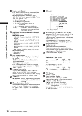
At a HEAD ROOM of -20 dB Not displayed when the LCD is on in CAMERA
mode. (Displayed when pre-recording, interval
-20dB -12dB 0dB
CH1 recording, or one-shot recording is set.)
CH2 27 Special recording display
This display appears when the REC FUNCTION
At a HEAD ROOM of -18 dB option of the setting menu RECORDING SETUP
-18dB -12dB 0dB screen is set to INTERVAL, ONE SHOT or LOOP,
CH1 and when PRE REC is set to ON.
CH2 Loop recording is not displayed when the LCD is
on.
20 Gain display 28 Lens chromatic aberration compensation
Displays the gain value of the image amplifier (CAC) indicator
configured. During a mode check, it indicates that lens
21 AWB operation display chromatic aberration compensation (CAC)
The white balance operation is indicated here. operates normally.
Viewfinder Screen Status Displays 69](https://image.slidesharecdn.com/ag-hpx500emanual-100120045233-phpapp01/85/Ag-Hpx500-E-Manual-69-320.jpg)
![Errors Camera status display
These are displayed when an error occurs in the unit, • ABW: ABW indicator
P2 card, tape, or other component. If the problem is • ABB: ABB indicator
not fixed by turning the power off and then on again, • AWB P3.2 K/AWB P5.6K: Displays the color
either replace the card or tape based on the error temperature assigned to PRST when the WHITE BAL
information, or consult with your dealer as to which switch is set to PRST. Also displayed when AWB is
one is to be purchased. performed in the PRST position.
• CANNOT REC • GAIN: Displayed when **dB GAIN is switched..
This is displayed during a recording error. • BACK LIGHT (OFF): Displayed during iris control
Chapter 4 Adjustments and Settings for Recording
• CANNOT PLAY when back light status is changed by pressing the
This is displayed when trouble has occurred during user button to which BACK LIGHT is assigned.
playback. • SPOT LIGHT (OFF): Displayed during iris control
• CARD ERR (1) (2) (3) (4) (1/2/3/4): Trouble has when back light status is changed by pressing the
occurred in the user button to which SPOT LIGHT is assigned.
P2 card found in • SHUTTER 1/XXXX (OFF): Displayed when the
the slot indicated shutter speed is changed.
by the number. • SCENE ******: Displays the name of a scene file
• CLIP ERROR: clip trouble selected by turning the SCENE FILE dial.
• UPDATING: Reading card data • ND NG: Displayed when the ND filter is not working
• ERROR: other type of trouble normally.
• SYSTEM ERROR • AUTO KNEE (ON/OFF): Displayed when changing
This is displayed when trouble has occurred in the the AUTO KNEE switch position.
system. Switch ON the power again.
• P2 MICON ERROR: No P2 microcomputer response
• P2 CONTROL ERROR: Trouble in P2 control USER buttons assignment
• REC RAM OVERFLOW: Recording RAM overflow
• TURN POWER OFF information (at mode check)
This message indicates that an abnormal event has
occurred, for example, that a card has been removed Displays the function assigned to each USER button.
during access or that a change in system frequency For details, see [Assigning Functions to USER
has been made. Turn the power off and then turn it buttons].
back on again.
• REC WARNING
This is displayed when trouble has occurred during ! LED light indication
recording. Carry out recording once again. If the
warning persists, consult your dealer. (at mode check)
• CARD ERR (1) (2) (1/2): Trouble has occurred in the
P2 card found in the slot Indicates why an ! LED is lit according to setting menu
indicated by the number. VF! LED screen settings.
●If the warning continues, turn off the power. • GAIN: Indicates the camera is using a gain value
●If the warning appears even when recording is other than 0 dB.
carried out again, replace the card with another • AWB: Indicates that the WHITE BAL switch is set to
one. PRST.
• ERROR: Other type of trouble • SHUT: Indicates the electronic shutter is operating.
• 1394 • FILT: Indicates filter setting.
This is displayed when trouble has occurred in the • EXT: Indicates when the lens extender is inserted.
1394 connections or signals. (P2 mode only)
• 1394 INITIAL ERROR: Connection error
• 1394 INPUT ERROR: Input error
• 1394 INPUT ERROR (OTHER FORMAT): (Wrong
input
format)
• LOW BATTERY:
Indicates that the battery is exhausted.
Viewfinder Screen Status Displays 71](https://image.slidesharecdn.com/ag-hpx500emanual-100120045233-phpapp01/85/Ag-Hpx500-E-Manual-71-320.jpg)
![Checking and displaying Setting the Marker Displays
shooting status Turn marker display on or off.
Select the display mode from the setting menu
• Hold down the DISP/MODE CHECK button in DISPLAY SETUP screen.
recording standby or during recording to display For directions on navigating the menu, see [Setting
the settings of each shooting function, the list of Menu Options].
functions assigned to USER buttons and all other
information. Press again to return to the regular DISPLAY SETUP
screen.
ZEBRA DETECT 80%
Chapter 4 Adjustments and Settings for Recording
• Press the DISP/MODE CHECK button during
MARKER ON
recording standby or recording clears all displays. SAFETY ZONE 90%
Press again to return to the regular display. DATE/TIME OFF
• These settings are maintained when the unit is LEVEL MATER ON
turned off and also when switching media and ZOOM ON
operating mode. CARD/BATT ON
• Display the following items on the viewfinder and P2CARD REMAIN TOTAL
LCD monitor screen by pressing the DISP/MODE
PUSH MENU TO RETURN
CHECK button or by configuring OTHER DISPLAY of
the DISPLAY SETUP screen of the setup menus. You can also press the USER button to which the
Audio dubbing MARKER function has been assigned to turn the
MODE marker on and off.
Displays DISPLAY mode
CHECK
ALL PARTIAL OFF
1 Time code display ❍ — — — —
AUTO/MANUAL switch
3 — ❍ ❍ ❍ ×
operation display
Recording format/
4 ❍ ❍ ❍ × ×
recording time display
5 Information display ❍ — × × ×
Squeeze information
6 ❍ ❍ ❍ ❍ ×
display
9 Calendar display ❍ ❍ — — —
Recording/playback
10 ❍ ❍ ❍*1 × ×
frame rate display
11 Shutter speed display ❍ ❍ ❍ ❍ ×
12 Audio level meter display ❍ ❍ — — —
13 IRIS display ❍ ❍ ❍ ❍ ×
14 Zoom position display ❍ ❍ — — —
15 Auto-IRIS control display ❍ ❍ ❍ ❍ ×
Media remaining
16 ❍ ❍ — — —
memory display
Recommended ND filter
18 ❍ ❍ ❍ ❍ ×
display
19 ND filter display ❍ ❍ ❍ × ×
20 Gain display ❍ ❍ ❍ ❍*2 ×
21 AWB information display ❍ ❍ ❍ ❍*3 ×
Scene file name/DUB
23 ❍ ❍ ❍ × ×
display
24 Media data display ❍ ❍ — — —
25 Operating status display ❍ ❍ — — —
Remaining media
26 ❍ ❍ — — —
display
Special recording
27 ❍ ❍ — — —
display
28 Safety zone display — — — — —
29 AWB, ABB error display ❍ × — — —
Chromatic aberration
30 ❍ × — — —
compensation display
❍: Displayed
×: Not displayed
—: Displayed depending on other settings
The item in ❍ in the MODE CHECK space appears when you
press and hold the DISP/MODE CHECK button.
The item in ❍ in the DISPLAY space disappears when you
press the DISP/MODE CHECK button.
*1 Not displayed when FRAME RATE is set to 60i or 50i.
*2 0 dB is not displayed.
*3 Only preset 3.2K and 5.6K are displayed.
72 Viewfinder Screen Status Displays](https://image.slidesharecdn.com/ag-hpx500emanual-100120045233-phpapp01/85/Ag-Hpx500-E-Manual-72-320.jpg)


![Setting Data Using an SD memory Formatting, Writing and
card
An SD or SDHC memory card (optional accessory)
Reading an SD memory
can be used as a setup card that stores up to four files card
of settings menu specifications.
This data allows you to quickly reproduce an optimum
Open the CARD FUNCTIONS screen from the setting
state. Regarding SD memory cards, please see
menu to format SD memory cards, write setting data
<Cautions in using SD memory cards>.
to SD memory cards and to read data stored on an SD
memory card.
Chapter 4 Adjustments and Settings for Recording
CARD FUNCTIONS
Handling SD memory cards
SCENE FILE
An SD memory card may be inserted or removed, USER FILE
either before or after the power is turned on. SD CARD FORMAT
To insert an SD memory card
Open the lid of the switch cover, and insert an SD
memory card (optional accessory) into the SD memory
card slot with the notch upward. Close the lid.
PUSH MENU TO RETURN
For an SD memory card formatted with a device that
does not support SD/SDHC standards, the message
“FORMAT ERROR” appears at the upper right of the
screen. In this case, reformat the card as follows.
To format an SD memory card
<Note>
SD memory cards may be formatted via the thumbnail
screen. For more information, see [Formatting SD
memory cards].
1 Navigate the menu to the <CARD
FUNCTIONS> screen.
<Note>
An SD memory card must be inserted with the right side
facing the slot. If the card is hard to insert, it may be 2 Turn the JOG dial button to move
the cursor to the menu option CARD
reversed or upside down. Do not force it into the slot.
Check the card before reinserting it. CONFIG.
To remove the SD memory card
Open the lid of the switch cover, and ensure that the 3 Press the JOG dial button.
BUSY lamp is not illuminated. Then, further depress
the SD memory card towards the main unit. This
releases the SD memory card from the insertion slot.
Take hold of the SD memory card and remove it. Close
4 To format the SD memory card, turn the
JOG dial button to move the cursor to
the lid. YES. Then, press the dial button.
• This formats an SD memory card.
SD memory cards must not be used or stored in
an environment where they may be CARD FUNCTIONS
• Exposed to high temperatures/humidities;
• Exposed to water droplets; or SCENE FILE
• Electrically charged. USER FILE
For storage, the SD memory card must be kept SD CARD FORMAT
YES
inserted into the AG-HPX500P/E with the lid closed.
PUSH MENU TO RETURN
Handling setup data 75](https://image.slidesharecdn.com/ag-hpx500emanual-100120045233-phpapp01/85/Ag-Hpx500-E-Manual-75-320.jpg)
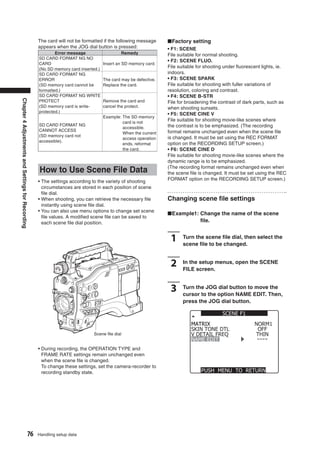
![■Example2: Save the F1 scene file to the
camera.
4 Turn the JOG dial button to move the
cursor to YES. Then, press the JOG dial
button. 1 Turn the JOG dial button to move the
cursor to the option LOAD/SAVE/INT.
SCENE F1 Then, press the JOG dial button.
MATRIX NORM1
SKIN TONE DTL OFF SCENE F1
V DETAIL FREQ THIN
Chapter 4 Adjustments and Settings for Recording
NAME EDIT LOAD/SAVE/INIT
OPERATION TYPE SAVE
YES
FRAME RATE INITIAL
SYNCRO SCAN 1/60.3
DETAIL LEVEL 0
V DETAIL LEVEL 0
PUSH MENU TO RETURN DETAIL CORING 0
CHROMA LEVEL 0
PUSH MENU TO RETURN
5 When the screen shown below appears,
use the JOG dial button to enter a 6-
character file name.
• Turning the JOG dial button changes the
2 Turn the JOG dial button to move the
cursor to the option SAVE. Then, press
character display in the following order: space the JOG dial button.
(❏)→ alphabet (A to Z) → numerics (0 to 9) →
symbols (; : < = > ? @ [ ] ^_-./). SCENE F1
• If the COUNTER RESET button is pressed
when the filename has been set, the LOAD/SAVE/INIT
characters are cleared. OPERATION TYPE SAVE
FRAME RATE INITIAL
NAME EDIT SYNCRO SCAN 1/60.3
DETAIL LEVEL 0
SW POSITION F2 V DETAIL LEVEL 0
DETAIL CORING 0
FLU0. CHROMA LEVEL 0
PUSH MENU TO RETURN
: PUSH PLAY/STOP
SEL : PUSH FF/REW
PUSH MENU TO RETURN
6 After you finish setting the filename,
press the MENU button.
• This completes the NAME EDIT change. A
change that has been confirmed is retained
after a power down and is not affected by dial
position.
Handling setup data 77](https://image.slidesharecdn.com/ag-hpx500emanual-100120045233-phpapp01/85/Ag-Hpx500-E-Manual-77-320.jpg)

![To title a file
5 Select YES using the JOG dial button,
and press the JOG dial button.
• In the following example, TITLE 1 is the
filename. 1 Perform steps 1 to 4.
• When writing is completed, WRITE OK
appears.
2 Use the JOG dial button to select
characters, then press the JOG dial
SCENE FILE (SD CARD)
button to move to the next character.
WRITE FILE 1 • You can input any of the following characters:
Chapter 4 Adjustments and Settings for Recording
YES PUSH STILL Space, A to Z, 0 to 9, : ; < = > ? @ [ ] ^_-./
• You can erase all characters using the
TITLE EDIT RESET button.
TITLE 1
SEL : PUSH FF/REW
3 After entering all the characters, press
the cursor button at the left end of the
PUSH MENU TO RETURN
characters, and then press the JOG dial
button.
6 Press the MENU button to cancel the
menu mode. <Note>
• If WRITE NG FORMAT ERROR appears, format the SD
memory card.
• If WRITE NG WRITE PROTECT appears, release the
protected status of the SD memory card.
To load a file • If WRITE NG CANNOT ACCESS appears, quit all other
Perform steps 1 to 3, select READ in step 4, and press operations (such as playback) before proceeding.
the JOG dial button. • If WRITE NG ERROR appears, the SD memory card may
When reading is completed, READ OK appears. be defective. Replace it.
Handling setup data 79](https://image.slidesharecdn.com/ag-hpx500emanual-100120045233-phpapp01/85/Ag-Hpx500-E-Manual-79-320.jpg)

![Using an NP-1 type battery pack
2 Insert the battery and slide it in the
direction of the arrow.
When replacing the battery holder, consult your
distributor.
1 Remove the battery holder.
Release lever
Chapter 5 Preparation
Battery holder
<Note>
●Removing the battery pack
Completely push down and hold the release
lever on the battery holder. Then, slide the
battery pack in the opposite direction to the
arrow while holding the lever down. 2 Mount the NP-1 type battery case on
the camera-recorder.
➀Tighten the mounting screws.
➁Tighten the power contact screws.
3 Setting the battery type.
• Select the battery type listed under BATTERY
➂Insert the upper part of the removed cover in
the direction of the arrow.
SELECT. Select the menu option BATTERY
➃Align the holes in the bottom part (metal part)
SELECT from the setting menu BATTERY
of the cover with the holes in the case, and
SETUP screen. Please refer to [BATTERY
secure the cover with the screw.
SETUP] for more information. <Note>
When mounting the battery holder, take care not
to pinch the connection cord.
■The following Anton/Bauer batteries can be
used:
• PROPAC14 Battery Case (for NP-1 type)
• TRIMPAC14
• HYTRON50
• HYTRON100
• HYTRON140
• DIONIC90
• DIONIC160
Power Supply 81](https://image.slidesharecdn.com/ag-hpx500emanual-100120045233-phpapp01/85/Ag-Hpx500-E-Manual-81-320.jpg)
![When using a V-mount type battery Using an AC Power Supply
pack
Mount the V-mount adapter plate. Insert the plate and
slide it in the direction of the arrow.
1 Plug the DC OUT connector into the
camera-recorder’s external DC input
socket.
Chapter 5 Preparation
DC IN Socket
AC Adapter
2 Turn the AC adapter power ON.
(If the AC adapter is equipped with a power
switch)
3 Turn the camera-recorder power switch
ON.
3 Setting the battery type.
• Select the battery type listed under BATTERY
• At power-on, a rush current occurs. Therefore,
use of an external AC power adaptor that assures
SELECT. Select the menu option BATTERY the power consumption twice as large as the
SELECT from the setting menu BATTERY total amount of all the devices connected to the
SETUP screen. unit. Also, use a DC cable of 10 A or more.
• When using a battery not listed under • When using an external power supply other
BATTERY SELECT: than the AC adapter, check the DC IN socket pin
If it is a NiCD battery, select “NiCd14(14V)” information to ensure correct polarity. If a +12 V
depending on the battery voltage. Set power supply is accidentally connected to the
the other items according to the battery GND terminal, this could cause a fire or personal
properties. If it is not a NiCd battery, select injury.
TYPE A or TYPE B and set the other items
according to the battery properties. Please
refer to [BATTERY SET UP] for more
information. Pin No. Signal
<Note> 1 GND
For information about the V-mount adapter plate, 1 4
please contact the store where you purchased 2 3 2, 3 -
the camera-recorder. 4 +12V
DC IN Socket
82 Power Supply](https://image.slidesharecdn.com/ag-hpx500emanual-100120045233-phpapp01/85/Ag-Hpx500-E-Manual-82-320.jpg)


![Preparing for Audio Input
Take the following steps to prepare the camera for
connecting audio input devices.
3 Connect the microphone cable to the
MIC IN jack on the camera.
When Using the Front
Chapter 5 Preparation
Microphone
The AJ-MC700P microphone kit (optional) includes a
microphone that can be mounted on the camera.
1 Open the microphone holder.
Viewfinder
MIC IN Jack
4 Set the AUDIO IN switch to [FRONT]
depending on the audio channel to be
Microphone holder
recorded.
2 Mount the microphone and tighten the
clamping screw.
Clamping Screw
AUDIO IN Switch
Preparing for Audio Input 89](https://image.slidesharecdn.com/ag-hpx500emanual-100120045233-phpapp01/85/Ag-Hpx500-E-Manual-89-320.jpg)
![When Using Audio Devices
1 Connect the audio device to the AUDIO
IN jack with the XLR cable.
2 Set the AUDIO IN switch to [REAR] for
the channel to which the XLR cable is
connected.
Chapter 5 Preparation
3 Set the LINE/MIC/+48V selector switch
on the rear panel to [LINE].
LINE/MIC/+48V Selector Switch
AUDIO IN Jack
AUDIO IN Switch
90 Preparing for Audio Input](https://image.slidesharecdn.com/ag-hpx500emanual-100120045233-phpapp01/85/Ag-Hpx500-E-Manual-90-320.jpg)


![It is possible to display only the selected thumbnails
in the thumbnail screen for playback. Please refer 3 Move the pointer to THUMBNAIL and
select with the SET button.
to [Switching the Thumbnail Display] for more
information. • The setting sub -menu appears.
THUMBNAIL Button • Select the desired item to specify the type of
thumbnail display.
Chapter 6 Manipulating Clips with Thumbnails
LCD Monitor
CURSOR and SET buttons
• ALL CLIP:
Thumbnail menu button
Display all clips.
• SAME FORMAT CLIPS:
Switching the Thumbnail The clips in the same recording format are displayed.
• SELECTED CLIPS:
Display Display randomly selected clips.
• MARKED CLIPS:
The display can be switched so that only those clips Display clips with shot marks attached.
matching the specified conditions are displayed in the • TEXT MEMO CLIPS:
thumbnail screen. Clips with text memos are displayed. Thumbnails at
text memo positions, time codes (TC), total number
of memos and the current order of the clips are
1 Press the MODE button to enter the
MCR mode.
displayed.
• SLOT CLIPS:
• The thumbnail screen appears on the LCD Display clips recorded in the P2 card inserted in the
monitor. specified slot.
• SETUP:
Various setup operations are performed.
2 Press the thumbnail menu button to
open the menu.
• EXIT:
The previous screen reappears.
■To delete a text memo
1 Select THUMBNAIL-TEXT MEMO CLIPS,
move the cursor to the text memo to be
deleted and press the SET button.
2 Move the cursor to the text memo
thumbnail to be deleted.
3 Press the MENU button to open the
setting menu and choose OPERATION
→ DELETE.
Thumbnail menu button
96 Thumbnail Screen](https://image.slidesharecdn.com/ag-hpx500emanual-100120045233-phpapp01/85/Ag-Hpx500-E-Manual-96-320.jpg)


![Setting of Clip Meta Data
Information such as the name of person who shot the Clip metadata content
video, the name of the reporter, the shooting location,
Clip Meta Data includes the following items:
or a text memo can be read from the SD memory card,
Underlined items can be set by reading the metadata
and can be recorded as Clip Meta Data.
upload file on the SD memory card. Other items are
set automatically during shooting. Using the latest
Reading Clip Meta Data (metadata update version of P2 viewer, metadata upload files can
upload) be written to SD memory cards using a PC. Download
the latest update version of P2 viewer from the
Chapter 6 Manipulating Clips with Thumbnails
following URL and install it to your PC:
1 Insert the SD memory card that
contains the Clip Meta Data (metadata http://panasonic.biz/sav/p2
upload file).
Regarding SD memory cards to be used, see
[Cautions in using SD memory cards].
<Note>
2 Press the MODE button to enter the
MCR mode.
The file which was edited by except P2 viewer is
displayed as “UNKNOWN DATA”, and may not be read.
• The thumbnail screen appears on the LCD You can set the underlined items by loading the
monitor. metadata upload file on the SD memory card. All other
items are automatically set during shooting.
• GLOBAL CLIP ID:
3 Press the thumbnail menu button to
open the menu.
Displays the global clip ID, which indicates the
shooting status of the clip.
• USER CLIP NAME:
Displays the clip name specified by the user.*
4 Select META DATA → LOAD from the
menu bar, and press the SET button.
* If the metadata upload file does not contain any
data, the global clip ID serves as the USER CLIP
NAME. The USER CLIP NAME recording method is
selectable. For more information, see [Selecting the
USER CLIP NAME recording method].
• VIDEO:
Displays [FRAME RATE] (frame rate of the clip),
[PULL DOWN], and [ASPECT RATIO].
• AUDIO:
[SAMPLING RATE] (sampling frequency of recorded
sound) and [BITS PER SAMPLE] (digitized bit[s] of
recorded sound).
• ACCESS:
Displays [CREATOR] (person who recorded the clip),
[CREATION DATE] (date when the clip was recorded),
[LAST UPDATE DATE] (date of the latest update of
the clip), and [LAST UPDATE PERSON] (person who
made the latest update of the clip).
5 Names of metadata upload files stored
on the SD memory card are displayed.
• DEVICE:
Displays [MANUFACTURER] (name of the device
manufacturer), [SERIAL NO.] (serial number of the
• Select the desired files using the cursor
device) and [MODEL NAME] (model name of the
buttons, and choose YES. Upload starts.
device).
• Uploaded metadata is retained even if the
• SHOOT:
power is turned off.
Displays [SHOOTER] (name of the person who shot
For confirmation of uploaded data, see
the video), [START DATE] (start date of shooting),
[Confirmation of Metadata Upload].
[END DATE] (end date of shooting), and [LOCATION]
ALTITUDE/LONGITUDE/LATITUDE/SOURCE/PLACE
NAME (altitude, longitude, latitude, and source of the
information and name of the location).
100 Setting of Clip Meta Data](https://image.slidesharecdn.com/ag-hpx500emanual-100120045233-phpapp01/85/Ag-Hpx500-E-Manual-100-320.jpg)
![• SCENARIO*: Selecting the USER CLIP NAME
Displays [PROGRAM NAME], [SCENE NO.], and
[TAKE NO.]. recording method
* Be sure to enter PROGRAM NAME when entering Select META DATA → USER CLIP NAME from the
SCENARIO. It is not possible to record only the menu bar to select the recording method. Two options
SCENE NO or TAKE NO. are available: TYPE1 and TYPE2.
• NEWS:
Displays [REPORTER] (name of the reporter), ●TYPE1
[PURPOSE] (purpose of shooting), and [OBJECT] USER CLIP NAME
(object of shooting). to be recorded
If clip metadata has been read in Uploaded data
• MEMO*:
If no clip metadata has been read
Displays the NO. (memo number), OFFSET (frame in or if the setting for recording clip
Same as GLOBAL CLIP
position from the beginning of the clip), PERSON ID (UMID data)
metadata has been turned off
(name of the person who recorded the text memo),
●TYPE2
and TEXT (memo content).
* Be sure to enter TEXT when entering MEMO. It is not USER CLIP NAME
Chapter 6 Manipulating Clips with Thumbnails
to be recorded
possible to record only PERSON or OFFSET.
Uploaded data +
If clip metadata has been read in
COUNT value*
<Note> If no clip metadata has been read
The AG-HPX500P/E only displays printable ASCII in or if the setting for recording clip Same as CLIP NAME
characters. metadata has been turned off
* The COUNT value is indicated as a four-digit number.
To set whether or not the uploaded The COUNT value is incremented each time a new clip is
metadata is recorded captured if clip metadata has been read in and TYPE2 has
been selected as the recording method.
Set ON/OFF by selecting META DATA → RECORD. The COUNT value can be reset using the following
procedure.
Select METADATA → PROPERTY → USER CLIP NAME.
Select “COUNT RESET” with the cursor and press the SET
button to reset the COUNT value to 1.
<Note>
When a P2 card with a memory capacity of 8 GB or more
is used in this unit and a one-time continuous recording
exceeds the prescribed duration (approx. 10 minutes for
DVCPRO50 or approx. 20 minutes for DVCPRO or DV) or
when a one-time recording extends over more than one
P2 card, the recording concerned will automatically be
undertaken as a separate clip. At this time, each clip will
be provided with its own COUNT value.
Setting of Clip Meta Data 101](https://image.slidesharecdn.com/ag-hpx500emanual-100120045233-phpapp01/85/Ag-Hpx500-E-Manual-101-320.jpg)

![Formatting P2 and SD Memory Cards
Formatting a P2 Card Formatting SD memory
cards
1 Press the MODE button to enter the
MCR mode.
SD memory cards can also be formatted from the
thumbnail screen. With an SD memory card inserted
• The thumbnail screen appears on the LCD
into the camerarecorder, perform the following
monitor.
operation:
Chapter 6 Manipulating Clips with Thumbnails
2 Press the thumbnail menu button to
open the menu.
1 Press the MODE button to enter the
MCR mode.
• The thumbnail screen appears on the LCD
monitor.
3 From the menu bar, select OPERATION →
FORMAT.
• The following screen appears. Select the slot
number for the P2 card you want to format.
2 Press the thumbnail menu button to
open the menu.
• Select EXIT if formatting is not required.
3 Select OPERATION → FORMAT.
• The following screen appears. Select “SD-
CARD”.
• Select “EXIT” if formatting is not required.
4 Use the CURSOR and SET buttons to
select YES in the screen that confirms
whether you want to format the card.
5 The selected P2 card is formatted. 4 Use the CURSOR and SET buttons to
select YES in the screen that confirms
whether you want to format the card.
5 The SD memory card is formatted.
<Note>
SD memory cards can also be formatted from the menu
screen.
For more information, see [Formatting, Writing and
Reading an SD memory card].
Formatting P2 and SD Memory Cards 103](https://image.slidesharecdn.com/ag-hpx500emanual-100120045233-phpapp01/85/Ag-Hpx500-E-Manual-103-320.jpg)
![Properties
The clip’s properties and the P2 card’s status are
displayed.
P2 Card Status Display
P2 Card Status Display Settings
Clip Property Select PROPERTY → CARD STATUS to set the
Select PROPERTY → CLIP PROPERTY. desired indication mode (remaining free space or used
The following screen appears. memory capacity) for the P2 card status display.
Chapter 6 Manipulating Clips with Thumbnails
3
1 Press the MODE button to enter the
MCR mode.
• The thumbnail screen appears on the LCD
1
monitor.
2
5 2 Press the thumbnail menu button to
open the menu.
4
3 Select PROPERTY → PROPERTY SETUP →
P2CARD CAP.
• The following screen appears. Select the
P2 card status display settings from the P2
CARD CAP menu option.
1 Clip number
2 Thumbnail
3 Slot number
4 Clip information
Various indicators that have been added to the
clip and also various kinds of data are displayed.
( appears if the P2 card is writeprotected)
• CLIP NAME: Clip name
• START TC: Time code value when recording
started
• START UB: User information value when
recording started
• DATE: Date when the recording was made
• TIME: Time when recording started • REMAIN:
• DURATION: Clip length Show remaining free space on the P2 card as
• V_FORMAT: Video signal format the P2 card status display.
• FRAME RATE: Playback frame rate • USED:
• REC RATE: Recording frame rate Show used memory capacity on the P2 card
This display appears when recording using as the P2 card status display.
a setting for the FRAME RATE item on the
SCENE FILE screen other than the default during
720P/24PN or 720P/30PN recording operation.
5 Clip metadata
The video and audio formats, videographer information
and other detailed data are displayed here. Use the
CURSOR button to select the item and press the SET
button. (For details on the clip metadata, see [Setting
of Clip Meta Data].)
104 Properties](https://image.slidesharecdn.com/ag-hpx500emanual-100120045233-phpapp01/85/Ag-Hpx500-E-Manual-104-320.jpg)

![SD memory card Status Confirmation of Metadata
Display Upload
The status display enables a confirmation of the SD • The contents of the metadata upload file that is read
memory card formatted condition, available memory from the SD memory card can be checked.
capacity etc. • Select META DATA → PROPERTY. The following
Select PROPERTY → DEVICES → SD CARD. screen appears:
■Screen showing SD memory card data
Chapter 6 Manipulating Clips with Thumbnails
For more information on each item, see [Setting of Clip
Meta Data].
• The META NAME is the meta data name written in
• SD STANDARD: This indicates whether the SD
the meta data upload file, and is not recorded in the
memory card was formatted
clip.
in compliance with the SD
standard (SUPPORTED/NOT
SUPPORTED).
• USED: Space used
• BLANK: Space available
• TOTAL: Total space
• NUMBER OF CLIPS: Number of clips
• PROTECT: This indicates that the SD memory card
is write protected.
106 Properties](https://image.slidesharecdn.com/ag-hpx500emanual-100120045233-phpapp01/85/Ag-Hpx500-E-Manual-106-320.jpg)


![DVCPRO DV Connection via 1394 Connector
Recording DVCPRO DV Subcode area time codes and user
bits
signals input to 1394 • When input from the IEEE1394 interface is selected
connector and the TCG switch is set to F-RUN and F-RUN TC
SAVE is set to 1394, the time code of the subcode
area input from the 1394 connector can be recorded
on a P2 card.
1 Connect a 1394 cable (DV cable).
• For details, see [Precautions in 1394
• To record user bits input from the 1394 connector on
a P2 card, set the setting menu 1394 UB REGEN to
Connections]. ON.
• Make sure that the signal format of the
camera and the connected device is the VAUX area time codes and user bits
Chapter 8 Connecting to External Devices (PC mode)
same.
When input from the IEEE1394 interface is selected,
time code and user bits of the VAUX area input
from the 1394 connector is recorded on a P2 card
2 To input via the IEEE1394 interface,
enter MCR mode and turn off
regardless of camera menu settings and switch
positions.
thumbnails.
Recording UMID (Unique Material
<Note> Identifier) data
• Input signals that have the same format as the setting
menu MCR FORMAT and REC MODE to the IEEE1394 When input from the IEEE1394 interface is selected,
interface. A signal in a different format will not be UMID data input via the 1394 connector is recorded
correctly recorded on a P2 card. Video and audio on a P2 card. When no UMID data is available, the
recording and EE type video and audio of signal inputs camera generates and records such data.
other than 1x speed playback signals may not work.
For details, see [Errors].
• Audio signal inputs are input signals from the 1394
Control of external devices through
connector. 1394 connection
• 32 kHz/4CH (12 bit) audio signals input via the
Using the 1394 interface to connect an external device
IEEE1394 interface are recorded as 48 kHz/4CH (16 bit)
on a P2 card.
for backup recording allows the operator to control
• It is not possible to use the GENLOCK IN connector to start and stop operation of backup recording from the
synchronize to an external reference signal. camera.
• Signals output from the VIDEO OUT, MON OUT or
AUDIO OUT connectors differ from actual input signals.
Use such signals for monitoring.
• The following functions do not operate.
1 Connect a 1394 cable (DV cable).
• For details, see [Precautions in 1394
• Pre-recording function Connections].
• Loop recording function • Set 1394 CONTROL in the setting menu
• Interval recording and one shot recording function OTHER FUNCTION screen to BOTH.
Time Code and User Bits
• When input from the IEEE1394 interface is selected, 2 Use the setting menu 1394 CMD SEL
to select the command for terminating
the time code or user bits input to the TC IN
connector cannot be recorded on a P2 card. recording that external devices receive.
• When input from the IEEE1394 interface is selected,
time code output from the TC OUT connector is not
<Note>
synchronized to the video signal output from the When the camera is set to REC RUN to perform backup
MON OUT connector. recording on a connected external device, the advance
of time code from the 1394 connector will stop when all
P2 cards have been fully recorded regardless of whether
backup recording continues.
DVCPRO DV Connection via 1394 Connector 125](https://image.slidesharecdn.com/ag-hpx500emanual-100120045233-phpapp01/85/Ag-Hpx500-E-Manual-125-320.jpg)
![Precautions in 1394 Connections P2 card recording times
• The camera does not supply power via the cable.
• Observe the following in connections using a 1394 Model AJ-P2 AJ-P2 AJ-P2
cable (DV cable). number C004HG C008HG C016RG
• Connect this unit to only one other device. Capacity 4 GB 8 GB 16 GB
DVCPRO DV Approx. Approx. Approx.
• Do not expose the 1394 connector to excessive
Audio 2CH 16 min. 32 min. 64 min.
force when connecting a 1394 cable (DV cable) to DVCPRO50 Approx. Approx.
avoid damaging the connector. Approx. 8 min.
Audio 4CH 16 min. 32 min.
• If an error (1394 INITIAL ERROR) should occur DVCPRO Approx.
Approx. 4 min. Approx. 8 min.
when making a connection, reinsert the 1394 cable HD*1 16 min.
or turn the camera off and then turn it back on DVCPRO HD Approx. Approx. Approx.
again. 720P/24PN 10 min. 20 min. 40 min.
• Make sure that the camera and all connected DVCPRO HD
Approx. Approx.
720P/30PN Approx. 8 min.
devices are connected to ground (or connected 16 min. 32 min.
720P/25P
to a common ground). If the equipment cannot be
connected to ground, turn off all connected devices *DVCPRO HD excludes 720P/30PN, 720P/24PN and
before connecting or disconnecting an IEEE 1394 720P/25PN.
cable.
• When connecting the unit to a device with a 4-pin • This unit cannot use AJ-P2C002SG (2 GB) cards.
connector, connect the cable to the 6-pin connector • The indicated capacities include a management area
so the total area available for recording is somewhat
Chapter 8 Connecting to External Devices (PC mode)
on the camera first.
• Be sure to properly connect the 1394 cable to a smaller.
personal computer with a 6-pin connector. Note
that inserting the plug the wrong way round may Splitting clips recorded on P2 cards
damage the connector. A continuous recording that is longer than the
durations given below on an 8 GB P2 card in this
camera will result in the automatic division of the
6-pin type
recording into different clips. Even so, the recordings
on the two clips can be handled as a single clip in
thumbnail operations (display, delete, recover, copy,
etc.) on a P2 device.
Such a recording may be handled as separate clips
by nonlinear editing software or on PCs.
4-pin type Recording format Recording duration
DVCPRO HD* Approx. 5 min.
DVCPRO50 Approx. 10 min.
• AV signals may be disrupted when connected DVCPRO DV Approx. 20 min.
devices are turned on and off or when the interface *DVCPRO HD excludes 720P/30PN, 720P/24PN and
cable is connected or disconnected. 720P/25PN.
• It may take the system a few seconds to stabilize
after switching input signals or changing modes. • Use of cards other than the above may require
Start recording after the system has stabilized. updating the camera driver.
• The AUDIO LEVEL control does not work in For details, see [Updating Camera Drivers].
recordings that involve IEEE1394 interface input or • For the latest information not available in the
output signals. Operating Instructions, visit the P2 Support Desk at
• Observe the following precautions when controlling the following Web sites.
a P2 memory card camera-recorder using PC http://panasonic.biz/sav/
application software (editing software).
• Recording cannot be inserted to a portion within
a clip. It can only be appended to the end of the
newest clip.
• Do not open the thumbnail screen as this will
prevent normal operation of the application
software.
• Unprocessed video and audio signals are output via
the IEEE 1394 interface during special playback.
When monitored on another device, these video and
audio signals may sound different than when played
back on this unit.
• CH1 and CH2 audio channel signals for the DV or
DVCPRO (25M) format are output via the IEEE1394
interface.
126 DVCPRO DV Connection via 1394 Connector](https://image.slidesharecdn.com/ag-hpx500emanual-100120045233-phpapp01/85/Ag-Hpx500-E-Manual-126-320.jpg)

![Inspecting the Camera Unit Inspecting the Memory
Recording Functions
1 Set the zoom to electric zoom mode
and check the zoom operation.
Make sure you successively carry out the inspections
from [Inspecting the P2 Card Recording] to [Inspecting
• Check that the image changes to telephoto
the Earphone and Speaker].
and wide angle.
Inspecting the P2 Card Recording
2 Set the zoom to manual zoom mode
and check the zoom operation.
• Turn the manual zoom lever to check that the 1 Check on the display inside the
viewfinder that the remaining P2 card
image changes to telephoto and wide angle.
recording capacity is sufficient.
Please refer to [P2 Card Status Display] for
3 Set the iris to automatic adjustment
mode and aim the lens at objects
information about P2 card remaining recording
capacity.
with different degrees of brightness,
to check that the automatic iris
adjustment operates normally.
2 Set the TCG switch to [R-RUN].
Chapter 9 Maintenance and Inspections
4 Set the iris to manual adjustment mode 3 Set the COUNTER button to TC.
and turn the iris ring, to check the
manual iris adjustment.
4 Press the camera’s REC START/STOP
button to check the following items:
5 While holding down the instant iris
automatic adjustment button, aim the
• The P2 access LED blinks in orange.
• The REC lamp inside the viewfinder lights up.
• System warnings do not appear inside the
lens at objects with different degrees viewfinder.
of brightness, to check that the instant
iris automatic adjustment operates
properly. 5 Press the camera’s REC START/STOP
button again.
• This step confirms that the P2 access LED is
6 Return the iris to automatic adjustment
mode and change the GAIN switch
on and showing orange, and the REC lamp in
the viewfinder is turned off.
setting to L, M, and H, to check the
following items:
• The iris is adjusted for objects with the same 6 Using the REC button on the handle,
repeat Steps 4 to 5 to check the same
brightness according to the switch setting.
• The gain value displayed on the viewfinder operation.
screen changes according to the switch • Check the VTR button on the lens in the
setting. same way.
7 When a lens with an extender is
mounted, set the extender to the
7 Press the PLAY button to check that the
clip that has just been shot is played
operating position to check that the back from the beginning.
extender operates properly. • Check that recording and playback operate
properly.
128 Inspections Before Shooting](https://image.slidesharecdn.com/ag-hpx500emanual-100120045233-phpapp01/85/Ag-Hpx500-E-Manual-128-320.jpg)
![Inspecting the Earphone and Speaker
8 Use the USER button to which the
SLOT SEL function has been assigned
to select P2 cards for recording when
more than one P2 card is inserted in
1 Turn the MONITOR control to check
that the speaker volume changes.
the card slots.
• Repeat the operations in Steps 4 to 5 and 7
to check that recording and playback operate
properly.
2 Connect an earphone to the PHONES
jack.
• Check that the speaker is turned off and the
microphone sound can be heard from the
earphone.
Inspecting the Audio Level Automatic
Adjustment
3 Turn the MONITOR control to check
that the earphone volume changes.
1 Set the AUDIO SELECT CH1 and CH2
switches to [AUTO].
Inspection for Using an External
2 Set the AUDIO IN switch to [FRONT]. Microphone
Chapter 9 Maintenance and Inspections
3 Aim the microphone connected to the 1 Connect an external microphone to the
REAR 1 and REAR 2 connectors.
MIC IN jack at an appropriate sound
source. Then, check that the level
displays for both CH1 and CH2 change
according to the sound level. 2 Set the AUDIO IN switch to [REAR].
3 Set the LINE/MIC/+48V selector
switches on the rear panel to [MIC] or
Inspecting the Audio Level Manual
[+48V], depending on the power supply
Adjustment
type of the external microphone.
• MIC: For a microphone with internal power
1 Set the AUDIO IN switch to [FRONT]. supply.
• +48V: For a microphone with external power
supply.
2 Set the AUDIO SELECT CH1 and CH2
switches to [MAN].
4 Set the LINE/MIC/+48V selector switch
on the rear panel to MIC or +48 V as
required by the power supply of the
3 Turn the AUDIO LEVEL CH1 and CH2
controls. external microphone.
• MIC: microphone with internal power supply
• Check that the level display increases when
• +48V: microphone powered from external
the controls are turned to the right.
power supply
4 Set the AUTO LEVEL CH3 and AUTO
LEVEL CH4 in the setting menu AUDIO 5 Aim the microphone at the sound
source and check that the sound level
SETUP screen to ON.
indication in the LCD or viewfinder
varies with changes in sound intensity.
5 Set the MONITOR SELECT switch to
CH3/CH4 and turn the AUDIO LEVEL
• The channels can also be checked separately
by connecting a single microphone to each
channel.
CH3/CH4 controls clockwise to check
that the level indication increases.
Inspections Before Shooting 129](https://image.slidesharecdn.com/ag-hpx500emanual-100120045233-phpapp01/85/Ag-Hpx500-E-Manual-129-320.jpg)
![Inspection of the clock, time code, and
user bits
1 Set the user bits as required.
Please refer to [Setting the User Bits] for the
setting procedures.
2 Set the time code.
Please refer to [Setting the Time Code] for the
setting procedures.
3 Set the TCG switch to [R-RUN].
• Press the COUNTER button to display the
time code on the LCD monitor or in the
viewfinder.
4 Press the REC START/STOP button.
• Check that the counter display number
changes as recording progresses.
Chapter 9 Maintenance and Inspections
5 Press the REC START/STOP button
again.
• Check that recording stops and the counter
display number stops changing.
6 Set the TCG switch to [F-RUN].
• Check that the counter display number
changes regardless of recording status.
7 Hold down the DISP/MODE CHECK
button to check the date and time on
the LCD monitor or in the viewfinder.
• Adjust the date and time setting if the DATE,
TIME and time zone is not correctly displayed.
For details, see [Setting Date and Time of
Internal Clock].
<Note>
Note that date and time data set for DATE, TIME,
and time zone is recorded in clips, and affects
the playback sequence, etc. at the time of
thumbnail manipulations.
130 Inspections Before Shooting](https://image.slidesharecdn.com/ag-hpx500emanual-100120045233-phpapp01/85/Ag-Hpx500-E-Manual-130-320.jpg)