Download to read offline
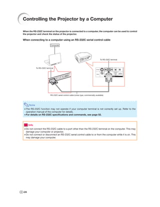
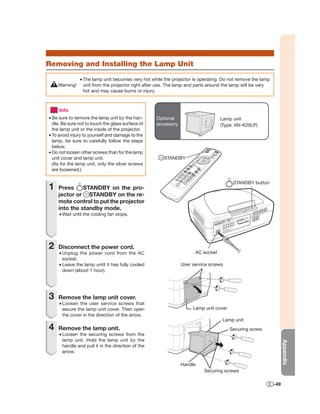
![Setting Up the Projector (Continued)
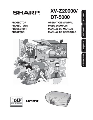
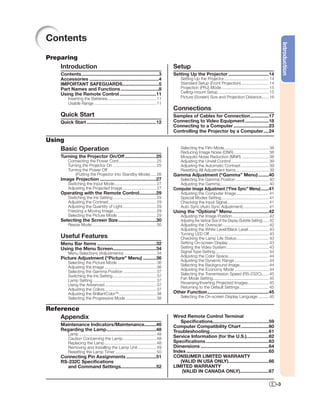
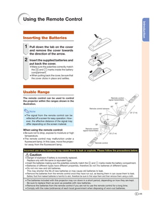
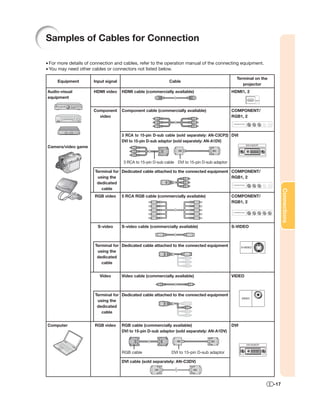
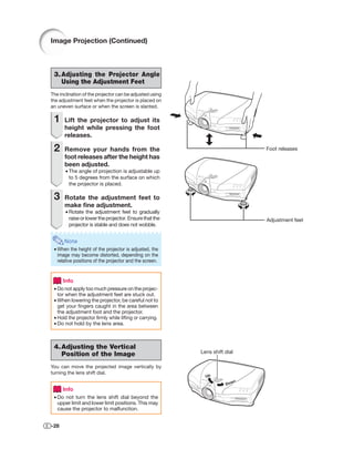
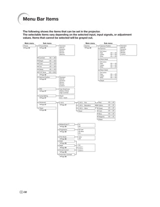
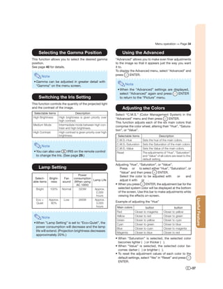
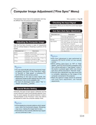
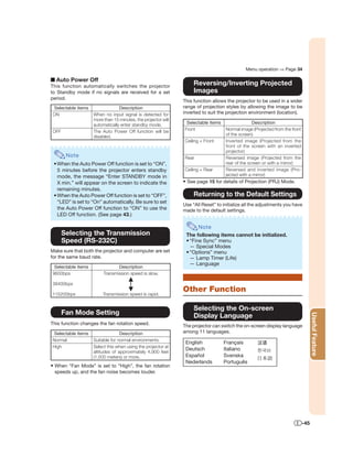
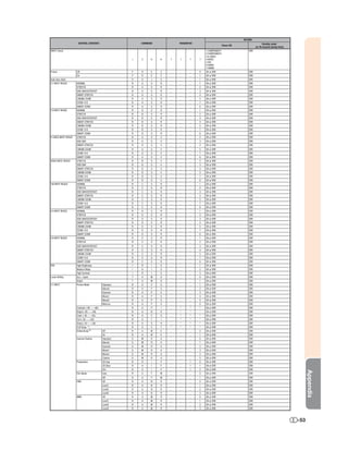
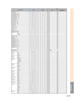
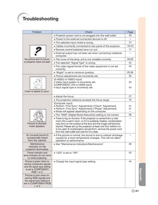
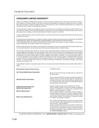
Picture (Screen) Size and Projection Distance
The projection screen size varies according to the distance from the lens of the projector to the screen. Install
the projector so that projected images are projected onto the screen at the optimum size by referring to the
table below. Use the values in the table as a reference when installing the projector.
When using a wide screen (16:9): In case of displaying the 16:9 picture on the whole of the 16:9 screen.
16 Distance from the lens center
Picture (Screen) size Projection distance [L]
to the bottom of the image [H]
Diag. (x) Width Height Maximum [L1] Minimum [L2] Lower [H1] Upper [H2]
9 300" 261.5" (6.6 m) 147.1" (3.7 m) 54'10" (16.7 m) 40'9" (12.4 m) –147" (–374 cm) 0" (0 cm)
250" 217.9" (5.5 m) 122.6" (3.1 m) 45'8" (13.9 m) 33'11" (10.3 m) –122" (–311 cm) 0" (0 cm)
200" 174.3" (4.4 m) 98.1" (2.5 m) 36'6" (11.1 m) 27'1" (8.3 m) –98" (–249 cm) 0" (0 cm)
: Projected image 150" 130.7" (3.3 m) 73.5" (1.9 m) 27'4" (8.3 m) 20'3" (6.2 m) –73" (–187 cm) 0" (0 cm)
120" 104.6" (2.7 m) 58.8" (1.5 m) 21'10" (6.7 m) 16'2" (4.9 m) –58" (–149 cm) 0" (0 cm)
110" 95.9" (2.4 m) 53.9" (1.4 m) 20'0" (6.1 m) 14'10" (4.5 m) –53" (–137 cm) 0" (0 cm)
100" 87.2" (2.2 m) 49" (1.2 m) 18'2" (5.5 m) 13'5" (4.1 m) –49" (–125 cm) 0" (0 cm)
80" 69.7" (1.8 m) 39.2" (1.0 m) 14'6" (4.4 m) 10'9" (3.3 m) –39" (–100 cm) 0" (0 cm)
60" 52.3" (1.3 m) 29.4" (0.7 m) 10'10" (3.3 m) 8'0" (2.4 m) –29" (–75 cm) 0" (0 cm)
40" 34.9" (0.9 m) 19.6" (0.5 m) 7'2" (2.2 m) 5'3" (1.6 m) –19" (–50 cm) 0" (0 cm)
x : Picture size (diag.) (inches) The formula for picture size and projection distance
L1 : Maximum Projection distance (ft/m) L1 = (0.05593x – 0.05550)/0.3048 (ft) H1 = –1.2453x/2.54 (in)
L2 : Minimum Projection distance (ft/m) L2 = (0.04158x – 0.05665)/0.3048 (ft) H2 = 0
When using a normal screen (4:3) and projecting 4:3 image (SIDE BAR Mode)
4 Distance from the lens center
Picture (Screen) size Projection distance [L]
to the bottom of the image [H]
Diag. (x) Width Height Maximum [L1] Minimum [L2] Lower [H1] Upper [H2]
3 250" 200" (5.1 m) 150" (3.8 m) 56'0" (17.1 m) 41'7" (12.7 m) –150" (–381 cm) 0" (0 cm)
200" 160" (4.1 m) 120" (3.0 m) 44'9" (13.6 m) 33'2" (10.1 m) –120" (–305 cm) 0" (0 cm)
150" 120" (3.0 m) 90" (2.3 m) 33'6" (10.2 m) 24'10" (7.6 m) –90" (–229 cm) 0" (0 cm)
: Screen 120" 96" (2.4 m) 72" (1.8 m) 26'9" (8.2 m) 19'10" (6.1 m) –72" (–183 cm) 0" (0 cm)
: Projected image 110" 88" (2.2 m) 66" (1.7 m) 24'6" (7.5 m) 18'2" (5.5 m) –66" (–168 cm) 0" (0 cm)
100" 80" (2.0 m) 60" (1.5 m) 22'3" (6.8 m) 16'6" (5.0 m) –60" (–152 cm) 0" (0 cm)
80" 64" (1.6 m) 48" (1.2 m) 17'9" (5.4 m) 13'2" (4.0 m) –48" (–122 cm) 0" (0 cm)
60" 48" (1.2 m) 36" (0.9 m) 13'4" (4.1 m) 9'10" (3.0 m) –36" (–91 cm) 0" (0 cm)
x : Picture size (diag.) (inches) The formula for picture size and projection distance
L1 : Maximum Projection distance (ft/m) L1 = (0.06845x – 0.05550)/0.3048 (ft) H1 = –1.524x/2.54 (in)
L2 : Minimum Projection distance (ft/m) L2 = (0.05089x – 0.05665)/0.3048 (ft) H2 = 0
When using a normal screen (4:3): In case of setting the 16:9 picture to the full horizontal width of the 4:3 screen.
4 Distance from the lens center
Picture (Screen) size Projection distance [L]
to the bottom of the image [H]
Diag. (x) Width Height Maximum [L1] Minimum [L2] Lower [H1] Upper [H2]
250" 200" (5.1 m) 150" (3.8 m) 41'11" (12.8 m) 31'1" (9.5 m) –112" (–286 cm) 0" (0 cm)
3 200" 160" (4.1 m) 120" (3.0 m) 33'6" (10.2 m) 24'10" (7.6 m) –90" (–229 cm) 0" (0 cm)
150" 120" (3.0 m) 90" (2.3 m) 25'1" (7.6 m) 18'7" (5.7 m) –67" (–171 cm) 0" (0 cm)
120" 96" (2.4 m) 72" (1.8 m) 20'0" (6.1 m) 14'10" (4.5 m) –54" (–137cm) 0" (0 cm)
110" 88" (2.2 m) 66" (1.7 m) 18'4" (5.6 m) 13'7" (4.1 m) –49" (–126 cm) 0" (0 cm)
: Screen
100" 80" (2.0 m) 60" (1.5 m) 16'8" (5.1 m) 12'4" (3.8 m) –45" (–114 cm) 0" (0 cm)
: Projected image
80" 64" (1.6 m) 48" (1.2 m) 13'3" (4.1 m) 9'10" (3.0 m) –36" (–91 cm) 0" (0 cm)
60" 48" (1.2 m) 36" (0.9 m) 9'11" (3.0 m) 7'4" (2.2 m) –27" (–69 cm) 0" (0 cm)
x : Picture size (diag.) (inches) The formula for picture size and projection distance
L1 : Maximum Projection distance (ft/m) L1 = (0.05133x – 0.05550)/0.3048 (ft) H1 = –1.143x/2.54 (in)
L2 : Minimum Projection distance (ft/m) L2 = (0.03817x – 0.05665)/0.3048 (ft) H2 = 0
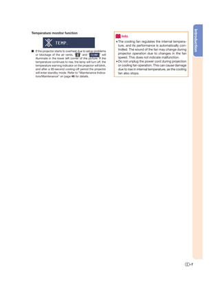
Note
• Allow a margin of error in the value in the diagrams above.
• When the distance from the lens center to the bottom of the image (H) is a negative number, this indicates
that the bottom of the image is below the lens center.
-16](https://image.slidesharecdn.com/sharpxv-z20000-110508040813-phpapp01/85/Sharp-xv-z20000-17-320.jpg)
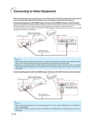
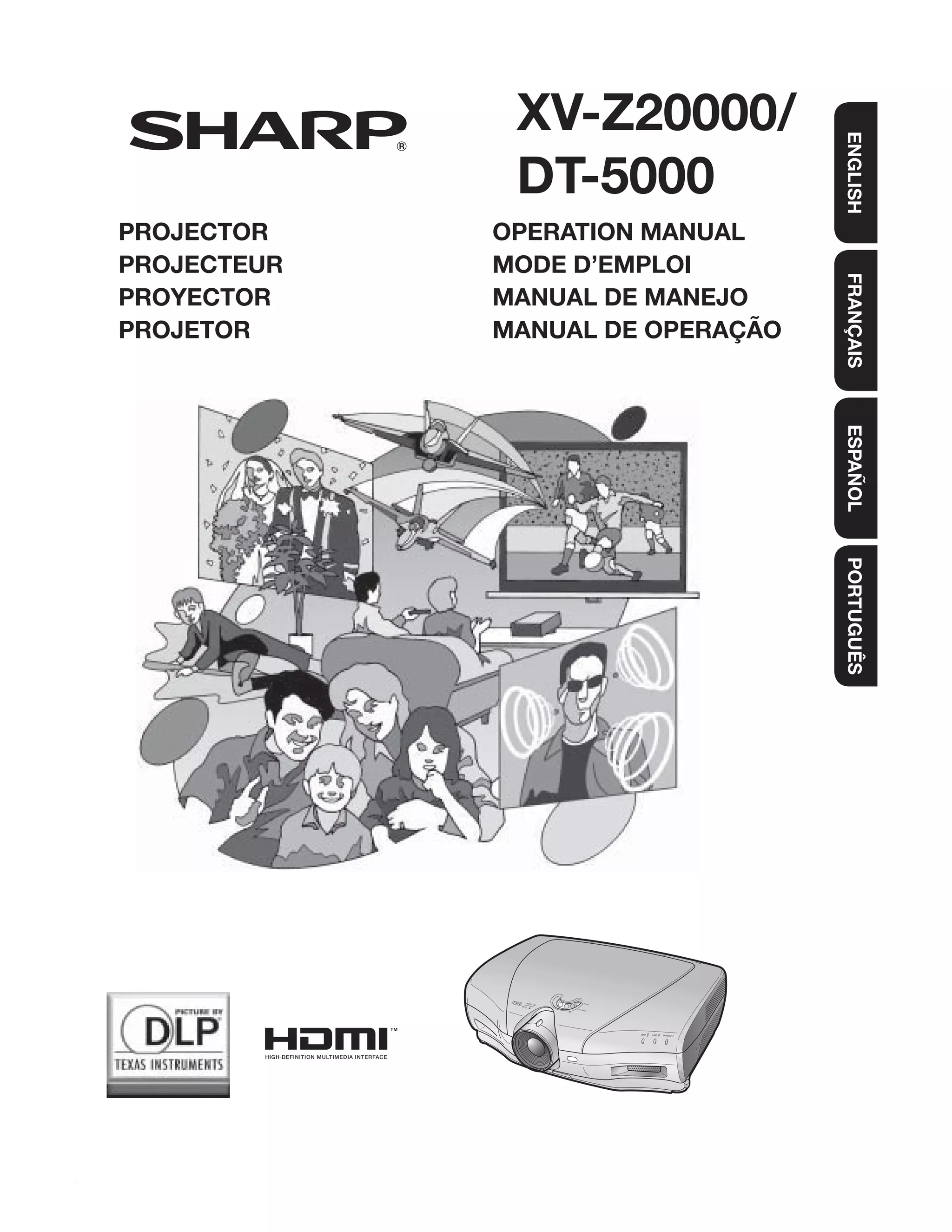
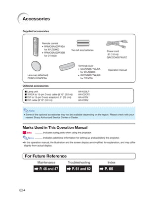
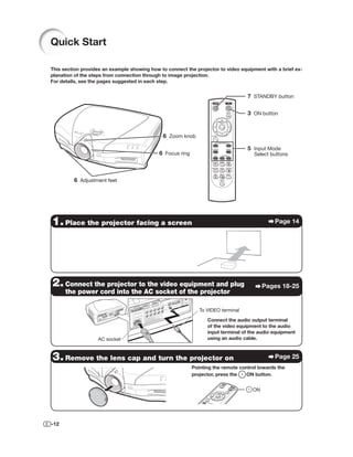
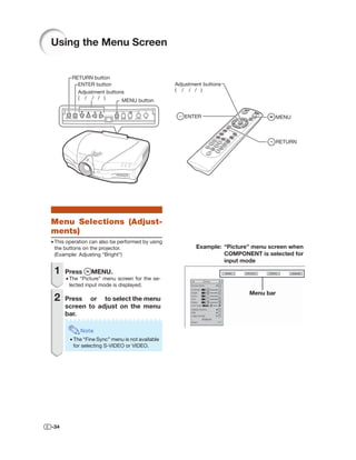
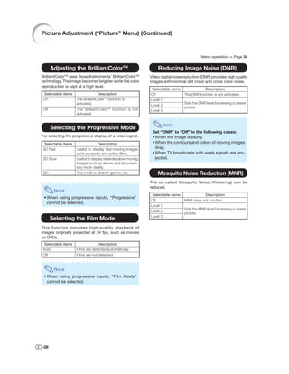
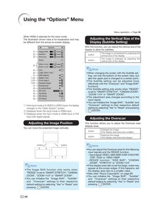
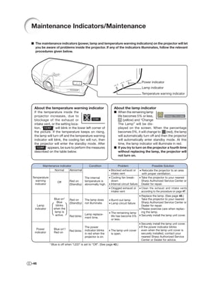
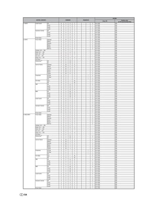
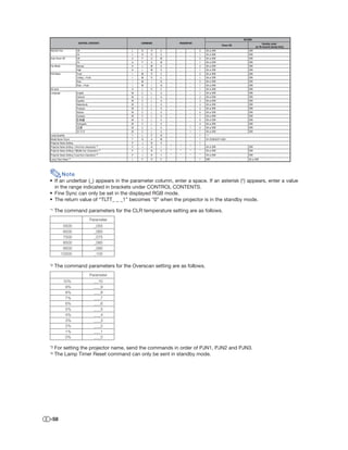
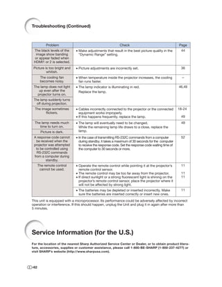
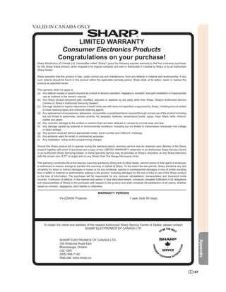
![Main menu Sub menu Main menu Sub menu
*1
Fine Sync Clock –150 +150 Options Image Shift –30 +30
Page 41 Page 42 Page 42
Phase –60 +60
Subtitle –30 +30
H-Pos –150 +150 Page 42
Overscan 10 0%
V-Pos –60 +60 Page 42
Reset
Reset
Page 42
Special Modes White Level –30 +30
Signal Info Resolution
Black Level –30 +30
Hor Freq
Vert Freq Page 43
LED On
Auto Sync Off Page 43 Off
Normal
High Speed Lamp Timer(Life)
Page 43
OSD Display On
Page 43 Off
When S-VIDEO or VIDEO is
selected for the input mode
Video System Auto
Page 43 PAL
SECAM
NTSC4.43
NTSC3.58
PAL-M
PAL-N
When COMPONENT is selected PAL-60
for the input mode
Signal Type Auto
Page 44 RGB
Component
When DVI is selected for the D.PC RGB
input mode D.PC COMP.
D.VIDEO RGB
D.VIDEO COMP.
A. RGB
A. COMP.
When HDMI is selected for the Auto
input mode RGB
YCbCr4:4:4
YCbCr4:2:2
*2
Color Space Auto
Page 44 ITU601
ITU709
*2,3
Dynamic Range Auto
Page 44 Standard
Enhanced
Background Logo
Page 44 Blue
None
Economy Mode RS-232C Port [ON/OFF]
Useful Feature
Pages 44, 45 Auto Power Off [ON/OFF]
RS-232C 9600 bps
Page 45 38400 bps
115200 bps
Fan Mode Normal
Page 45 High
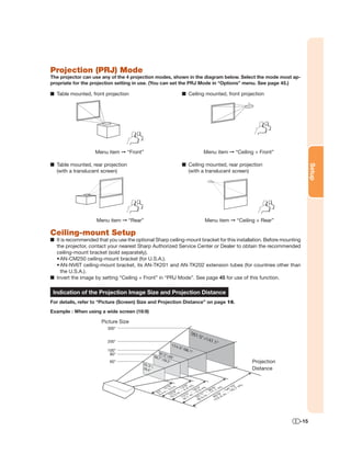
PRJ Mode Front
Page 45 Ceiling + Front
Rear
All Reset
Ceiling + Rear
Page 45
Language English Svenska
Page 45 Deutsch Português
Español
Nederlands
Français
Italiano
*1: The “Fine Sync” menu is not available for S-VIDEO or VIDEO Input.
*2: Can be set for HDMI Input.
*3: Can be set for DVI Input.
-33](https://image.slidesharecdn.com/sharpxv-z20000-110508040813-phpapp01/85/Sharp-xv-z20000-34-320.jpg)
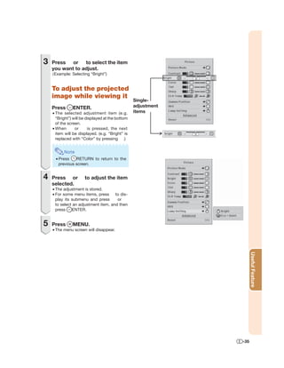
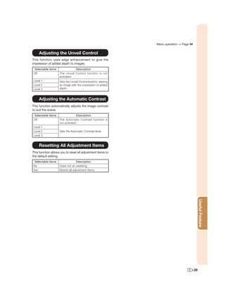
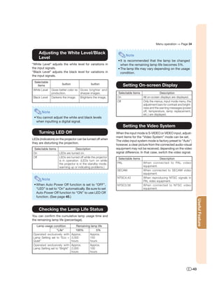
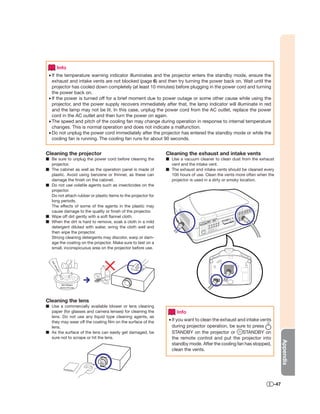
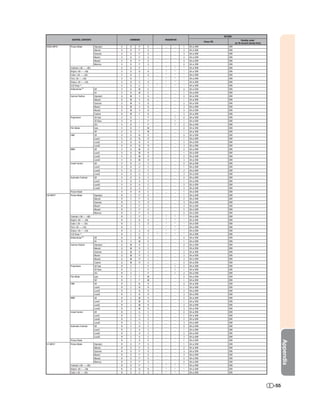
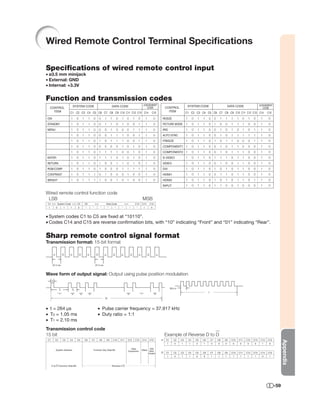
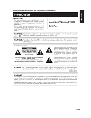
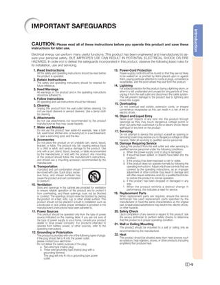
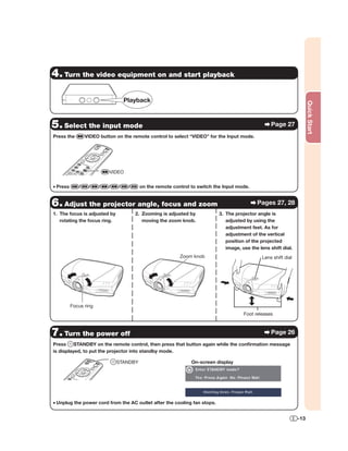
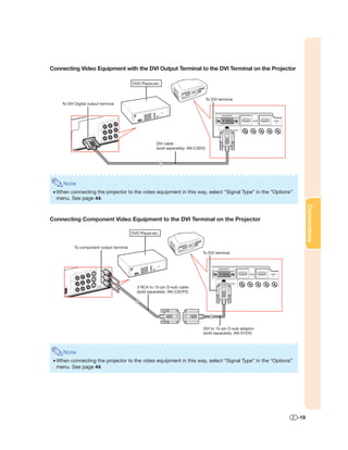
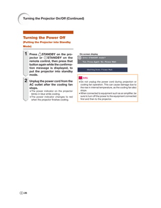
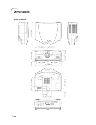
![Specifications
Product type Projector
Model XV-Z20000/DT-5000
Video system NTSC 3.58/NTSC 4.43/PAL/PAL-M/PAL-N/PAL 60/SECAM
DTV480I/DTV480P/DTV720P/DTV1080I/DTV1080P
Display method DLP® chip
DLP® panel Panel size: 0.95"
No. of dots: 2,073,600 dots (1,920 [H] × 1,080 [V])
Lens 1–1.35 × zoom lens, F2.5–8, f = 38.9–52.4 mm
Projection lamp 220 W SHP lamp
Video input signal RCA Connector: VIDEO (VIDEO), composite video, 1.0 Vp-p, sync negative, 75 Ω termi-
nated
S-video input signal 4-pin Mini DIN connector (S-VIDEO)
Y (luminance signal): 1.0 Vp-p, sync negative, 75 Ω terminated
C (chrominance signal): Burst 0.286 Vp-p, 75 Ω terminated
Component input signal RCA Connector (COMPONENT/RGB1, 2)
Y: 1.0 Vp-p, sync negative, 75 Ω terminated
PB: 0.7 Vp-p, 75 Ω terminated
PR: 0.7 Vp-p, 75 Ω terminated
Analog RGB/Digital input signal 29-pin DVI-I terminal (DVI)
<Digital>
Input impedance 50 Ω
Input level 250-1000 mV
<Analog>
Input Impedance 75 Ω
Input level 0.7 Vp-p
<Synchronization signal>
• Separate sync / Composite sync
Input level TTL level
Input impedance 1 KΩ
• Green on sync
Input level (Synchronizing input) 0.286 Vp-p
Input Impedance 75 Ω
HDMI input signal HDMI terminal (Video signal only)
TRIGGER terminal Power jack: DC 12 V output
Computer control signal 9-pin D-sub connector (RS-232C Terminal)
Horizontal resolution 520 TV lines (NTSC 3.58 input), 750 TV lines (DTV 720P input)
Pixel clock 12–150 MHz
Vertical frequency 43–100 Hz
Horizontal frequency 15–81 kHz
Rated voltage AC 100–240 V
Input current 3.3 A (When using AC 100 V)
Rated frequency 50/60 Hz
Power consumption 320 W (Lamp Setting “Bright”)/
265 W (Lamp Setting “Eco + Quiet”) with AC 100 V
310 W (Lamp Setting “Bright”)/
260 W (Lamp Setting “Eco + Quiet”) with AC 240 V
Power consumption (standby) 0.1 W (AC 100 V, RS-232C OFF) - 0.18 W (AC 240 V, RS-232C OFF)
Heat dissipation 1,200 BTU/hour
Operating temperature 41°F to 95°F (+5°C to +35°C)
Storage temperature –4°F to 140°F (–20°C to +60°C)
Cabinet Plastic
I/R carrier frequency 38 kHz
Dimensions (approx.) 18 11/16" × 6 51/64" × 16 5/32" (475 (W) × 172.5 (H) × 410.2 (D) mm) (main body only)
Weight (approx.) 20.7 lbs. (9.4 kg)
Replacement parts Remote control, Power cord, Lens cap, Terminal cover, Projector operation manual
As a part of policy of continuous improvement, SHARP reserves the right to make design and specification changes for
product improvement without prior notice. The performance specification figures indicated are nominal values of produc-
tion units. There may be some deviations from these values in individual units.
Appendix
-63](https://image.slidesharecdn.com/sharpxv-z20000-110508040813-phpapp01/85/Sharp-xv-z20000-64-320.jpg)


1) This document is the operation manual for the SHARP Projector model XV-Z20000/DT-5000. 2) It provides important safety warnings and instructions on setting up, connecting, and operating the projector. 3) The manual covers basic operation instructions including turning the projector on/off, selecting inputs, adjusting the image size, and contains troubleshooting information.


