Download to read offline


![Introducing the R-4
The R-4’s controls and connectors
Top panel
fig.panel-1.eps_50
1 1
2 2
3 4 5 6
7 8 9
13
16
10
17
11 12
14 15
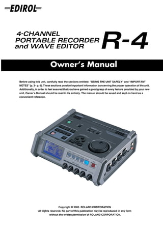
1 Internal mics [MIC-L, MIC-R]
These are stereo mics built into the R-4. The audio entering MIC-L is recorded on the 1L channel, while
audio picked up by MIC-R is recorded on the 1R channel. If you’re recording via the internal mics, set the
System Settings menu item Recording Setup to Int-Mic. For details, refer to “Recording from the internal
mics” (p. 30).
* Don’t connect anything to input jacks you’re not using.
2 Internal speakers
These are built-in speakers for monitoring. If you want sound to be heard from the internal speakers, set
the System Settings menu item Speaker to ON. For details, refer to “Playing back” (p. 34).
* No sound will be heard from the internal speakers if you’ve connected headphones to the Headphone jack ( 37 ).
Nor will sound be heard from the internal speakers while recording or in recording-standby mode; this prevents
acoustic feedback from occurring.
3 Power switch [POWER]
This turns the power on/off. To turn the power on or off, press and hold the power switch for about two
seconds. The power switch is lit green when the power is on.
Don’t turn the power off during recording or playback. Before you turn off the power, you must make sure
that recording or playback is stopped.
* If you accidentally turn off the power during recording, the data that was being recorded will not be stored on the
hard disk.
* The hard disk may be damaged if you turn off the power of the R-4 while data is being read from or written to the
hard disk (such as during recording or playback). You must also be careful not to turn off the power while data is
being transferred between the hard disk and the CompactFlash card.
* Never turn off the power while the R-4’s display indicates Now Connecting... or Now Processing! Doing so will
cause the R-4 to become unstable, and could even damage the internal hard disk.
* During recording, pressing the power switch will not turn off the power.
* The hard disk may be damaged if you turn off the power of the R-4 while data on the hard disk is being written or
read, such as during playback or waveform editing.
9](https://image.slidesharecdn.com/r-4manual-110331034827-phpapp01/85/Edirol-R-4-9-320.jpg)
![Introducing the R-4
fig.panel-1.eps_50
1 1
2 2
3 4 5 6
7 8 9
13
16
10
17
11 12
14 15
4 Hold switch [HOLD]
By selecting the HOLD ON position, you can disable the panel buttons so that unwanted operations will not
occur if a button is pressed accidentally.
However, even if this switch is set to HOLD ON, the phantom power switches 5 , limiter switch 6 ,
input level select switches 38 , Input level knobs 25 , and Monitor level knob 26 will still be
operable.
5 Phantom power switches [PHANTOM POWER]
These switch the phantom power on/off for the XLR type connectors of the combo input jacks located on
the right panel. Since separate switches are provided for channels 1/2 and channels 3/4, you can turn
phantom power on/off separately for these channels.
fig.jack-type
* Always turn the phantom power off when connecting any device other than
condenser microphones that require phantom power. You risk causing damage
if you mistakenly supply phantom power to dynamic microphones, audio XLR plug
playback devices, or other devices that don’t require such power. Be sure to
check the specifications of any microphone you intend to use by referring to
the manual that came with it.
TRS phone
This instrument’s phantom power: 48 V DC, 8 mA Max Phone plug plug
(unbalanced) (balanced)
(total of all channels must be 25 mA or less)
6 Limiter switch [LIMITER]
This is an on/off switch for an input level limiter in the analog circuitry.
When the input level is too high, the limiter compresses the input level appropriately to prevent distortion.
The limiter switch turns limiting on/off for all channels 1–4 together. However, the input level is detected
separately for each channel. You cannot turn the limiter on/off separately for each channel.
10](https://image.slidesharecdn.com/r-4manual-110331034827-phpapp01/85/Edirol-R-4-10-320.jpg)
![Introducing the R-4
7 Wave edit button [WAVE EDIT]
This button takes you to Wave Edit mode, where you can edit the waveform using operations such as Trim,
Divide, Combine, and Merge. For details, refer to “Editing” (p. 48).
You won't be able to enter Wave Edit mode during playback or recording, or if the R-4’s hard disk contains
no files that the R-4 can handle.
WAV files are the only type of files that the R-4 can handle.
8 Effect button [EFFECTS]
This button takes you to Effect mode, where you can make effect settings.
For details, refer to “Effects setting” (p. 55).
9 System button [SYSTEM]
This button takes you to a mode where you can make various settings for the R-4.
For details, refer to “System settings” (p. 60).
10 Marker [MARKER]
Clear button [CLEAR]
This button deletes a marker you assigned using the Mark button. Markers will be deleted successively,
starting at the marker located immediately before the current location.
button
This button moves you to the marker that is immediately before the current location (the previous marker).
If the current playback location is earlier than the first marker, pressing this button will take you to the
beginning of the project. You will also move to the beginning of the project if no markers have been set.
button
This button moves you to the marker that is immediately after the current location (the next marker).
If the current playback location is at the last marker, pressing this button will take you to the end of the
project. You will also move to the end of the song if no markers have been set.
Mark button [MARK]
By pressing this button you can assign a marker to a desired location in the project file. Markers are
numbered sequentially starting at the beginning of the project.
11 A-B Repeat button [A-B REPEAT]
This button lets you repeatedly play back the region between two points (A and B) in the project. Simply
assign marker A and marker B while the project is playing, and playback will repeat between markers A
and B.
fig.repeat-a
1. During playback, press the A-B Repeat button once. A
That point becomes the beginning (marker A) of repeat playback.
fig.repeat-b
2. Press the A-B Repeat button once again. That point will be the end A B
(marker B) of repeat playback.
fig.repeat-ab
The region you specified in steps 1 and 2 will play repeatedly. To cancel repeat
playback, press the A-B Repeat button once again. A B
12 Display button [DISPLAY]
This button switches the contents of the R-4’s display.
For details, refer to “Display” (p. 18).
11](https://image.slidesharecdn.com/r-4manual-110331034827-phpapp01/85/Edirol-R-4-11-320.jpg)
![Introducing the R-4
fig.panel-1.eps_50
1 1
2 2
3 4 5 6
7 8 9
13
16
10
17
11 12
14 15
13 Cursor/Monitor Select buttons [CURSOR/MONITOR SELECT]
Use these buttons to select items shown in the display. When you’re in the main screen, you can press the
up/down buttons to select the channel that you want to monitor.
For details, refer to “Display” (p. 18).
14 Exit button [EXIT]
Use this button to return to the previous screen or to cancel an operation.
15 Enter/Finder button [ENTER/FINDER]
Use this button to confirm a setting or finalize a value. You can also press this when you want to use the
Finder function. For more about the Finder function, refer to “The Finder screen” (p. 41).
16 Scrub dial [SCRUB/VALUE]
Use this dial to select among items for which settings are made, or to modify a value. While stopped or
when playback is paused, you can turn the scrub dial to move the current location forward or backward.
17 Shuttle dial [SHUTTLE]
While the project is playing, turn this dial clockwise to play rapidly forward, or counterclockwise to play
rapidly backward. When the project is stopped, this dial advances the time counter.
12](https://image.slidesharecdn.com/r-4manual-110331034827-phpapp01/85/Edirol-R-4-12-320.jpg)
![Introducing the R-4
Front panel
fig.panel-2.eps_50
18 19 20 21 22 23 24
25 26
18 Display
This shows various information about the R-4’s status.
For details, refer to “Display” (p. 18).
19 PREV button [PREV]
Pressing the PREV button while a project is playing or stopped will take you to the beginning of the project
(00:00:00). Pressing this button at the beginning of a project will take you to the preceding project.
You can also press and hold down this button to rewind. This is available both while playing and while
stopped.
* If the system setting Player Setup parameter Play Mode is set to Single, you can't move to the previous or next
project during playback.
20 NEXT button [NEXT]
Pressing the NEXT button will take you to the next project. You can also press and hold this button to fast-
forward. This is available both while playing and while stopped.
* If the system setting Player Setup parameter Play Mode is set to Single, you can't move to the previous or next
project during playback.
21 Stop button [STOP]
This button stops playback or recording. If you press the STOP button during playback, the counter will
maintain the time at which you pressed the STOP button.
22 Pause button [PAUSE]
This button pauses playback or recording.
23 Play button [PLAY]
This button starts playback. The PLAY button is lit blue during playback.
During playback, you can press the PLAY button once again to play at double-speed. During double-
speed playback, press the PLAY button once again to return to normal playback. During double-speed
playback, the lower part of the display will indicate PLAY X2. Double-speed playback will change the
pitch.
* If you want to turn off the double-speed playback feature, go to the System Settings menu and in Player Setup,
turn X2 Play OFF. For details, refer to “2 Player Setup” (p. 62).
24 Record button [REC]
Recording will begin immediately when you press the REC button. The REC button is lit red during
recording. If you hold down the PAUSE button and press the REC button, the REC button will blink
red, and the R-4 enters recording-standby mode. Recording will begin when you then press the REC
button or 22 PAUSE button.
25 Input level knobs 1–4 [INPUT GAIN]
These knobs adjust the input level of combo input jacks 1–4 ( 39 ). Input levels of the internal mics
( 1 ) are adjusted by knob 1 (MIC-L) and knob 2 (MIC-R).
26 Monitor level knob [MONITOR]
This adjusts the output volume of the internal speakers ( 2 ) and the headphone jack ( 37 ).
You can’t adjust the volume of the line output jacks ( 40 ). If you need to adjust the volume of the line
output jacks, adjust the controls of the external speakers or playback system connected to the line output
jacks.
13](https://image.slidesharecdn.com/r-4manual-110331034827-phpapp01/85/Edirol-R-4-13-320.jpg)
![Introducing the R-4
Side panel (left)
29 30 31
27
33 34
32
28 35 36 37
27 Digital input connector [DIGITAL IN]
If you want to record a digital signal, connect a coaxial-type cable to this connector. The digital input signal
is recorded in stereo on channels 1L and 1R. If you want to record in monaural, you’ll need to change the
Rec Mode setting in the System Settings menu. For details, refer to “1 Recording Setup” (p. 60).
28 Digital output connector [DIGITAL OUT]
This connector outputs a digital signal. You can use a coaxial-type cable to connect this to a digital
recording device such as a DAT or MD recorder. This connector provides the same audio signal as the line
output jacks ( 40 ) and headphone jack ( 37 ), but in digital form.
29 L connector [L-CONNECTOR]
You can use a stereo mini-mini-plug LANC cable to connect this to a video device that is equipped with a
LANC connector. When you begin recording on your video device, the R-4 will begin recording in tandem.
When you stop recording on your video device, the R-4 will also stop recording.
For details, refer to “Connecting a video device that has a LANC connector” (p. 74).
30 USB connector [USB]
Use the included USB cable to connect this to your computer. Projects recorded on the R-4 can be moved or
copied to your computer. Files from your computer can also be moved or copied to the R-4’s hard disk.
31 AC adaptor jack [DC IN]
Connect the included AC adaptor to this jack.
32 Cord hook
Use this to secure the AC adaptor cable.
33 Eject button
Press this when you want to remove the CompactFlash card inserted in the memory card slot 34 .
34 Memory card slot [MEMORY CARD]
You can insert a CompactFlash card into this slot.
Projects you record on the R-4 can be copied to a CompactFlash card for backup or to transfer them to a
computer.
The R-4 is able to use only TYPE 1 CompactFlash memory cards. Microdrive cards are not supported.
For details on handling CompactFlash cards, refer to “Handling memory cards” (p. 70).
14](https://image.slidesharecdn.com/r-4manual-110331034827-phpapp01/85/Edirol-R-4-14-320.jpg)
![Introducing the R-4
35 Grounding terminal
Depending on the circumstances of a particular setup, you may experience a discomforting sensation, or
perceive that the surface feels gritty to the touch when you touch this device, microphones connected to it,
or the metal portions of other objects. This is due to an infinitesimal electrical charge, which is absolutely
harmless. However, if you are concerned about this, connect the ground terminal (see figure) with an
external ground. When the unit is grounded, a slight hum may occur, depending on the particulars of your
installation. If you are unsure of the connection method, contact the nearest Roland Service Center, or an
authorized Roland distributor, as listed on the “Information” page.
Unsuitable places for connection
• Water pipes (may result in shock or electrocution)
• Gas pipes (may result in fire or explosion)
• Telephone-line ground or lightning rod (may be dangerous in the event of lightning)
36 Security Slot [ ]
http://www.kensington.com/
37 Headphone jack [PHONES]
Connect a set of headphones to this jack. Use the monitor level knob ( 26 ) to adjust the volume. If you
connect headphones, sound will not be heard from the internal speakers ( 2 ).
15](https://image.slidesharecdn.com/r-4manual-110331034827-phpapp01/85/Edirol-R-4-15-320.jpg)
![Introducing the R-4
Side panel (right)
fig.panel-3.eps_50
40
38 39 38
38 Input level select switches
Set these switches to either the MIC or LINE position depending on the type of device connected to
channels 1/L and 2/R or channels 3/L and 4/R.
MIC If a mic is connected
LINE If an audio device is connected via an analog connection
39 Combo input jacks 1–4
These are analog audio input jacks compatible with mic preamps. They accept either XLR or 1/4” phone
plugs; you can use whichever is most convenient for the equipment you’re connecting. Balanced or
unbalanced signals can be connected.
You can use combo input jacks 1–4 as four channels of monaural input or as two stereo pairs, 1/2 and 3/4.
For details, refer to “1 Recording Setup” (p. 60).
* The XLR type jacks can provide 48 V phantom power, allowing you to connect phantom-powered condenser mics.
In this case, turn on the phantom power switch ( 5 ).
fig.XLR-TRS
This instrument is equipped with balanced (XLR/ GND(SLEEVE)
TRS) type jacks. Wiring diagrams for these jacks are 1:GND
2:HOT
HOT(TIP)
shown below. Make connections after first checking 3:COLD
the wiring diagrams of other equipment you intend
COLD(RING)
to connect.
40 Line output jacks [LINE OUT]
These jacks output an analog audio signal. You can use RCA phono cables to connect them to powered
speakers, audio equipment, a mixer, etc. These jacks output the same signal as the digital output
connector ( 29 ) and the headphone jack ( 37 ).
The nominal output level is fixed at -10 dBV, and the volume of these jacks cannot be adjusted.
16](https://image.slidesharecdn.com/r-4manual-110331034827-phpapp01/85/Edirol-R-4-16-320.jpg)

![Introducing the R-4
Display
While playing or stopped
The main screen
The R-4’s main screen provides information about the project and the operational status of the R-4.
You can press the [DISPLAY] button to switch the contents of the display.
fig.play-disp.eps
Project name Progress bar Total time
Time
counter
Level scale
dBFS Sampling frequency
Channel Sample size
names (bit depth)
Marker indicators
Clip level indicators
Output
assignments
Power source
Channel level meters Date and time
Output level meters
Status indication Clip level indicators
Indicates the name of the project. If you copy WAV files from your computer
via USB to the R-4’s internal hard disk, this will show the file name. File names
Project name
containing double-byte characters (e.g., Japanese) will not be displayed cor-
rectly, but they can be played.
Indicates the time that has elapsed from the beginning of the project to the
Time counter
current location. Indicated in terms of hours: minutes: seconds.
Progress bar Indicates the current playback location relative to the entire project.
Total time Indicates the total time of the entire project.
Level scale Shows the audio level of each channel in real time. The markings are relative
Clip level indicators to 0 dBFS (Full Scale) of the digital signal. For example, 12 means -12 dBFS. C
Channel level meters is clipping level (0 dBFS).
This area shows up to four channel names. If you’re using one stereo channel,
this will indicate 1L and 1R. If you’re using two stereo channels, this will in-
Channel names dicate 1L, 1R, 2L, 2R.
For a monaural project, this area will show 1, 2, 3, and 4 according to the num-
ber of channels.
These show how the audio of each channel is assigned to the L/R output
channels. L means that the audio is assigned to the left channel, R to the right
channel, and LR to both left and right channels. Channels for which no indi-
cation appears will not be output. When you're in the main screen, you can
Output assignments
press the [CURSOR] up/down buttons to select the channel that you want to
monitor.
The output is sent to the PHONES jack, line output jacks, and digital output
connector.
Sampling frequency Indicates the sampling frequency and sample size (bit depth) of the currently
Sample size selected project.
The number at the left indicates the marker located immediately before the
Marker indicators current time counter value. The number at the right indicates the total number
of markers assigned in the currently selected project.
18](https://image.slidesharecdn.com/r-4manual-110331034827-phpapp01/85/Edirol-R-4-18-320.jpg)
![Introducing the R-4
Output level meters These are the output level meters. They show the final output levels of the L
and R channels, to which the various channels have been mixed. You can use
Clip level indicators the monitor level sliders of the mixer screen to adjust the level of each channel.
From the left, the level meter is calibrated at -36, -24, -12, and -6 dBFS.
Indicates how power is being supplied to the R-4. The plug icon is shown if
Power source power is being supplied by the AC adaptor, and the battery icon is shown if
power is being supplied by batteries.
In the main screen, you can press the [DISPLAY] button to switch the progress bar area so it shows the
remaining project time (REMAIN).
fig.play-disp2.eps
Remaining time
During playback, this indicates the remaining time from the current location
Remaining time
to the end of the project.
The mixer screen
From the main screen, press the [DISPLAY] button twice to move to the Mixer screen.
This screen lets you adjust the volume balance for monitoring.
fig.play-disp3.eps
Channel names Monitor output indicators
Channel level
Channel level meters
sliders
Output level meters
Use these to adjust the playback level of each channel. Use the left/right
[CURSOR/FINDER] buttons to select a slider, and turn the [SCRUB/VALUE]
dial to adjust the value. Each slider provides adjustment within the range 0–
120. The default value is 100.
Channel level sliders
* The settings are not stored in the project; they are remembered by the R-4
itself. When you turn off the power, the settings will revert to their default
values.
* These settings do not affect the recording levels.
19](https://image.slidesharecdn.com/r-4manual-110331034827-phpapp01/85/Edirol-R-4-19-320.jpg)
![Introducing the R-4
While recording
The main screen
The R-4’s main screen provides information about the project and the operational status of the R-4.
You can press the [DISPLAY] button to switch the contents of the display.
Recordable time Total recording time
Time counter
Indicates the elapsed time from the beginning of the project you’re recording
Time counter
until the current location. Indicated in terms of hours: minutes: seconds.
During recording, this indicates the remaining time that recording to the hard
disk can take place. The remaining time will depend on the sampling
Recordable time frequency (Sample Freq.), sample size (Rec Bit), and recording mode (Rec
Mode) settings. The indication shows how much longer you can record with
the current settings.
Indicates the total time from the beginning of recording to the current
location.
* Even if you record continuously, another new project will be created
Total recording time automatically when the project reaches 2 GB in size, and recording will
continue. Even for a recording that spans multiple projects in this way, the
elapsed time since you first pressed the [REC] (record) button will be shown
here.
* For an explanation of the other indications, refer to “While playing or stopped” (p. 18).
From the main screen, you can press the [DISPLAY] button to make the recordable time area show the
remaining hard disk capacity instead.
Remaining hard disk capacity
Remaining hard disk
Indicates the remaining free capacity on the internal hard disk.
capacity
20](https://image.slidesharecdn.com/r-4manual-110331034827-phpapp01/85/Edirol-R-4-20-320.jpg)


![Getting ready to use the R-4
Connecting the AC adaptor and turning the power on
* After you’ve made connections correctly, you must turn on the power using the steps below. If you don’t follow the
correct order, you may cause malfunctions or damage your speakers.
* Due to a circuitry protection feature, this unit requires a few moments after power-up before it is ready for normal
operation.
* If you connect the AC adaptor when batteries are installed, the power will be supplied from the AC adaptor.
fig.adaptor.eps
Turning the power on
1 Connect the DC plug of the AC adaptor to the AC adaptor jack located on the left side panel of the R-4.
* Use only the included AC adaptor.
2
Plug the AC adaptor into an AC power outlet.
* To prevent the inadvertent disruption of power to your unit (should the plug be pulled out accidentally), and to
avoid applying undue stress to the AC adaptor jack, anchor the power cord using the cord hook, as shown in the
illustration.
3 To turn the power on, press and hold the R-4’s [POWER] switch for about two seconds.
Wait until the main screen appears.
Turning the power off
1 From the main screen, press and hold the R-4’s [POWER] switch for about two seconds to turn the
power off.
* If you disconnect or reconnect the AC adaptor, the power will turn off even if batteries are installed. Please turn off
the power on the R-4 itself before you change between AC adaptor power and battery power.
24](https://image.slidesharecdn.com/r-4manual-110331034827-phpapp01/85/Edirol-R-4-24-320.jpg)
![Getting ready to use the R-4
Installing batteries and turning the power on
Types of batteries you can use
• AA alkaline batteries (LR6)
• AA nickel metal-hydride (HR15/51)
(The R-4 cannot recharge nickel metal-hydride batteries. You’ll need to use a separate charger.)
* You must set the R-4’s System Settings menu item “5 System Setup” (p. 63) to specify the type of batteries
you’ve installed. The R-4 will not operate correctly if you’ve specified a battery type that does not match the batteries
you’ve actually installed.
1
Make sure that the R-4 is turned off, and disconnect the AC adaptor from the AC adaptor jack.
2 Detach the battery cover from the bottom panel of the R-4.
* When turning the unit upside-down, handle with care to avoid
dropping it, or allowing it to fall or tip over.
3 Insert eight AA batteries into the battery compartment,
making sure to observe the correct polarity (+ and -
symbols).
4 Replace the battery cover.
5
Turn on the R-4.
6
Press the [SYSTEM] button.
7
Use the [CURSOR] up/down buttons to select 5 System Setup.
8 Press the [ENTER] button.
9 Using the [SCRUB/VALUE] dial, set the Battery Type to Alkaline if you’ve installed alkaline batteries,
or to Ni-MH if you’ve installed nickel metal-hydride batteries. The setting is activated as soon as you
select it.
10
When you’ve finished making settings, press the [EXIT] button.You’re returned to the previous screen.
11 When you’re back in the System Menu screen, press the [EXIT] button once again.
Although the indication [ENTER] will be blinking in the display, if you don’t need to make additional
settings, press the [EXIT] button to return to the main screen.
Caution when using the R-4 on battery power
• If you operate on battery power for an extended time, the batteries will become hot. Be careful not to
burn yourself.
• We recommend that you use alkaline batteries, which have a longer life.
• Don’t mix new batteries with used batteries, and don’t mix batteries of differing types.
• If you won’t be using the R-4 for an extended time, we recommend that you remove the batteries to
prevent leakage or other accidents.
• When using a USB cable to connect the R-4 to your computer, you must use the AC adaptor to prevent
the loss of power while the connection is active.
25](https://image.slidesharecdn.com/r-4manual-110331034827-phpapp01/85/Edirol-R-4-25-320.jpg)

![Recording
Recording from a connected mic
Here’s how to record an audio source from a mic connected to the R-4’s combo input jack.
fig.mic-1.eps
Turn this ON
if you're using a
condenser mic.
Set to MIC
Adjust the
input level
● Connections
Connect your mic to the combo input jack.
If you’re monitoring through external speakers, acoustic feedback (a screech or whine) may occur,
depending on the position of the mic relative to the speakers. If this occurs, take the following actions.
1. Point the mic in a different direction
2. Move the mic away from the speakers
3. Lower the monitoring volume
● Input level select switch
Set this to the MIC position.
● Phantom power switch
If you’ve connected a phantom-powered condenser mic, turn this ON.
fig.input-analog.eps
● System settings
Press the R-4's [SYSTEM] button.
In 1 Recording Setup, set Input Select to Analog.
Set the other items in 1 Recording Setup as appropriate for the
recording you want to make.
* For more about system settings, refer to “System settings” (p. 60).
● Limiter
Turn this ON if you want to prevent unexpectedly loud sounds or strong attacks from producing clipping
noise.
The limiter threshold is -10 dB relative to digital full scale, and the compression ratio is 1:3.
27](https://image.slidesharecdn.com/r-4manual-110331034827-phpapp01/85/Edirol-R-4-27-320.jpg)
![Recording
● Input level knobs
These knobs adjust the input levels.
If you’re recording in stereo, these knobs control the following signals.
Channel 1 STEREO 1 L-channel INPUT GAIN 1 knob
Channel 2 STEREO 1 R-channel INPUT GAIN 2 knob
Channel 3 STEREO 2 L-channel INPUT GAIN 3 knob
Channel 4 STEREO 2 R-channel INPUT GAIN 4 knob
Adjusting the input level
1. Hold down the [PAUSE] button and press the [REC] (record) button.
The R-4 will enter recording-standby mode. In recording-standby mode, the [REC] (record) button will
blink, and the display will indicate REC STANDBY.
2. Play sound into the microphone at the actual volume that you expect to record.
3. Gradually turn the input level knob toward the right.
4. Adjust the level so that the level meter shown in the display
reaches a point slightly before C (clip level). If the recording
level is too low, quiet sounds will not be recorded. If the
recording level is too high, soft sounds will be distorted,
producing a crackling noise in the recording.
* The level meter indicates the clip level (C) at 0 dBFS (FS = full scale). For
example, 12 indicates -12 dBFS. level meter (dBFS)
● Record button [REC]
If you want to begin recording immediately, press the [REC] (record) button. Recording will begin.
Recording-standby
If you want to put the R-4 in recording-standby mode so that Recording-standby
you can prepare for recording, hold down the [PAUSE]
button and press the [REC] (record) button.
In recording-standby mode, the [REC] (record) button will blink
and the display will indicate REC PAUSE.
Recording will begin immediately when you press the [REC]
(record) button or the [PAUSE] button in recording-standby
mode or while paused.
28](https://image.slidesharecdn.com/r-4manual-110331034827-phpapp01/85/Edirol-R-4-28-320.jpg)

![Recording
Recording from the internal mics
Here’s how to record an audio source via the R-4’s internal mics.
● Phantom power switch
Turn this OFF.
fig.input-intmic.eps
● System settings
Press the R-4's [SYSTEM] button.
In 1 Recording Setup, set Input Select to Int-Mic.
Set the other items in 1 Recording Setup as appropriate for the
recording you want to make.
* For more about system settings, refer to “System settings” (p. 60).
● Input level knobs
Adjust the input level.
Refer to “Adjusting the input level” (p. 28).
Input levels of the internal mics are adjusted by knob 1 (MIC-L) and knob 2 (MIC-R).
● Record button [REC]
Press the [REC] (record) button to begin recording.
For details on recording-standby, refer to “Recording-standby” (p. 28).
● Other settings
If you want to monitor the sound that’s being recorded, connect headphones to the PHONES jack and use
the monitor level knob to adjust the volume.
Adjusting the monitor level knob won’t affect the level of the sound that’s actually being recorded.
To play back the recorded sound, refer to “Playing back” (p. 34).
30](https://image.slidesharecdn.com/r-4manual-110331034827-phpapp01/85/Edirol-R-4-30-320.jpg)
![Recording
Recording digital audio from a digital device
Here’s how to record from a digital device connected to the R-4’s digital input jack.
fig.digital.eps
CD/MD player for playback DIGITAL IN
DIGITAL OUT
● Connections
Connect your digital device to the digital input jack. You’ll need a separately available coaxial-type cable
to connect your device to the R-4’s digital input jack.
fig.input-digital.eps
● System settings
Press the R-4's [SYSTEM] button.
In 1 Recording Setup, set Input Select to Digital.
Set the other items in 1 Recording Setup as appropriate for the
recording you want to make.
* For more about system settings, refer to “System settings” (p. 60).
* The R-4 is not able to synchronize to the clock signal of the digital input connector. Regardless of the sampling
frequency that is being input, the incoming digital audio data will be converted to the sampling frequency (Rec
Freq.) and sample size (Rec Bit) that are specified in Recording Setup.
● Record button [REC]
Press the [REC] (record) button to begin recording.
For details on recording-standby, refer to “Recording-standby” (p. 28).
● Other settings
If you want to monitor the sound that’s being recorded, connect headphones to the PHONES jack and use
the monitor level knob to adjust the volume.
Adjusting the monitor level knob won’t affect the level of the sound that’s actually being recorded.
* If you’re recording the digital input, you can’t use the input level knob to adjust the input level.
To play back the recorded sound, refer to “Playing back” (p. 34).
31](https://image.slidesharecdn.com/r-4manual-110331034827-phpapp01/85/Edirol-R-4-31-320.jpg)
![Recording
Recording analog audio
Here’s how to record from an audio device connected to the R-4’s combo input jacks.
fig.LINE-1.eps
Audio playback system
Phantom power (CD player, record player, etc.)
is not required,
so turn this OFF
R
L
Set to LINE
Adjust the input level
Set to minimum
Raise slowly if not used
● Connections
Connect your audio device to the combo input jacks.
You’ll need to use phone-jack audio cables (sold separately).
* When connection cables with resistors are used, the volume level of equipment connected to the combo input jacks
may be low. If this happens, use connection cables that do not contain resistors, such as those from the Roland PCS
series.
● Input level select switch
Set to LINE.
● Phantom power switch
Turn this OFF.
fig.input-analog.eps
● System settings
Press the R-4's [SYSTEM] button.
In 1 Recording Setup, set Input Select to Analog.
Set the Rec Mode to STEREOx1.
Set the other items in 1 Recording Setup as appropriate for the
recording you want to make.
* For more about system settings, refer to “System settings” (p. 60).
32](https://image.slidesharecdn.com/r-4manual-110331034827-phpapp01/85/Edirol-R-4-32-320.jpg)
![Recording
● Input level knobs
Adjust the input level 1 (L) and 2 (R) knobs. If there are channels to which you have not connected anything,
turn their input level knobs to the minimum position.
Refer to “Adjusting the input level” (p. 28).
● Record button [REC]
Press the [REC] (record) button to begin recording.
For details on recording-standby, refer to “Recording-standby” (p. 28).
● Limiter
Turn this OFF if you’re recording an audio source whose levels have already been regularized (in contrast
to a live audio source whose levels might change unpredictably), or if you have already checked the
maximum volume levels that are going to occur.
Turn this ON if you need to prevent clipping (distortion) that might be caused by unexpectedly loud
volumes or strong attacks.
● Other settings
If you want to monitor the sound that’s being recorded, connect headphones to the PHONES jack and use
the monitor level knob to adjust the volume.
Adjusting the monitor level knob won’t affect the level of the sound that’s actually being recorded.
To play back the recorded sound, refer to “Playing back” (p. 34).
33](https://image.slidesharecdn.com/r-4manual-110331034827-phpapp01/85/Edirol-R-4-33-320.jpg)
![Playing back
This section explains various procedures and methods by which you can play back the projects in the R-4’s
internal hard disk and the audio material you recorded on the R-4. Make the correct settings and
connections before you play anything back.
• Connections before playback.............................. (p. 34)
• Settings before playback ...................................... (p. 36)
• Playing back ............................................................. (p. 38)
Connections before playback
Connecting headphones
Headphones are a convenient way to monitor while you’re recording or immediately after recording.
1. Turn the [MONITOR] level knob all the way to the left to minimize the volume.
2. Connect your headphones to the PHONES jack.
3. Slowly turn the [MONITOR] level knob toward the right to adjust the volume.
Connecting amplified speakers
Here’s how to connect amplified speakers that have line input jacks or a digital input jack.
1. Switch off the power on the R-4.
2. Minimize the volume of the speakers you want to connect, and turn off their power.
3. Depending on the type of speakers you are using, connect the R-4’s [LINE OUT] line input jacks or
[DIGITAL OUT] digital output jack to your amplified speakers.
4. Switch on the R-4’s power.
5. Next, switch on your speakers, and gradually increase the volume to the desired level.
* The R-4 does not provide a way to adjust the volume of the audio that is output from its line output jacks.
Connecting a mixer or other analog device
(analog connection: line output jacks)
Here’s how to connect a mixer or other audio device that has line input jacks.
1. Switch off the power on the R-4.
2. Minimize the volume of the mixer or other device you’re going to connect.
3. Connect the R-4’s [LINE OUT] line input jacks to your mixer.
You’ll need separately available audio cables (not included) for connecting to the R-4’s line output
jacks.
4. Switch on the R-4’s power.
5. Next, switch on your mixer, and gradually increase the volume to the desired level.
* The R-4 does not provide a way to adjust the volume of the audio that is output from its line output jacks.
34](https://image.slidesharecdn.com/r-4manual-110331034827-phpapp01/85/Edirol-R-4-34-320.jpg)
![Playing back
Connecting an MD recorder or other digital recording device
(digital connection: digital output connector)
You can connect an MD recorder or other device that has a digital input connector, and use it to record the
sound played back by the R-4.
fig.basic-disp.eps
The sampling frequency of the project you’re playing back will
be the sampling frequency of the audio that’s output from the
digital output connector.
1. Switch off the power on the R-4.
2. Switch off your MD recorder.
3. Connect the R-4’s [DIGITAL OUT] jack to the digital input jack of your MD recorder.
* You’ll need a separately available coaxial-type cable (not included) for connecting the R-4’s digital output
jack to your digital device.
4. Switch on the R-4’s power.
5. Next, switch on your MD recorder.
* The R-4 does not provide a way to adjust the volume of the digital audio signal.
35](https://image.slidesharecdn.com/r-4manual-110331034827-phpapp01/85/Edirol-R-4-35-320.jpg)
![Playing back
Settings before playback
Player Setup
fig.recording-1.eps
1 Press the R-4’s [SYSTEM] button.
The system menu screen appears in the display.
fig.player-setup2.eps
2 Use the [CURSOR] buttons to choose 2 Playing Setup, and
press the [ENTER] button.
The Recording Setup screen appears.
3 Use the [SCRUB/VALUE] dial to choose the Play Mode value.
* The setting is applied as soon as you select it. You don’t need to press
the [ENTER] button.
Make settings for the following items as well.
Player Setup
Menu Playback method
settings
Selects the playback mode.
Single
Only the selected project will play.
Play Mode
The projects in the folder containing the currently selected project will
Sequential
play consecutively.
Selects whether playback will repeat.
If Play Mode is Single, only that project will play repeatedly. If it is
Repeat OFF, ON Sequential, the projects in the folder containing the currently select-
ed project will play consecutively, and then the projects in the same
folder will again play consecutively from the beginning.
This enables/disables the function that provides double-speed play-
back when you press the [PLAY] button a second time during play-
back (i.e., when you press [PLAY] twice).
X2 Play OFF, ON
The indication PLAY X2 will appear in the lower part of the display.
Normal playback will resume when you press the [PLAY] button
once again.
* For more about system settings, refer to “System settings” (p. 60).
36](https://image.slidesharecdn.com/r-4manual-110331034827-phpapp01/85/Edirol-R-4-36-320.jpg)
![Playing back
Speaker
You can use the R-4’s built-in speakers to monitor the sound without having to connect headphones or
other equipment.
fig.recording-1.eps
1
Press the R-4’s [SYSTEM] button.
The system menu screen appears in the display.
fig.speaker-on.eps
2
Use the [CURSOR] buttons to choose 3 Speaker Switch, and
press the [ENTER] button.
The Speaker screen appears.
Speaker Switch setting Output destination
Internal speakers
ON Line output jacks
Digital output jack
Line output jacks
OFF
Digital output jack
* You can’t monitor via the internal speakers while recording. You’ll need to monitor through headphones. Note that
sound will not be output from the speakers if headphones are connected. If you want to use the internal speakers,
you must disconnect the headphones.
* For more about system settings, refer to “System settings” (p. 60).
37](https://image.slidesharecdn.com/r-4manual-110331034827-phpapp01/85/Edirol-R-4-37-320.jpg)
![Playing back
Playing back
Normal playback
After you’ve performed the steps described in “Connections before playback” (p. 34) and “Settings
before playback” (p. 36), proceed as follows.
1
Select the project that you want to play.
In the main screen, press the [ENTER/FINDER] button. In the Finder screen that appears, use the up/
down [CURSOR] buttons and the [SCRUB] dial to select a project. For more about the Finder screen,
refer to “The Finder screen” (p. 41).
Alternatively, you can use the front panel’s [PREV] button or [NEXT] button to select the project you
want to play. The projects are in alphabetical order.
2 Press the [PLAY] button.
The selected project will play.
3 Slowly raise the [MONITOR] level knob to the desired volume for listening.
* Projects with names beginning with “.” are ignored, and will not be shown.
* The project name will not be displayed correctly if the project name contains double-byte characters (e.g., Japanese).
To ensure that you can view the file name correctly, don’t use double-byte characters in the filename.
* Projects whose filename extension is other than .pjt or .wav will be ignored, and will not be shown.
38](https://image.slidesharecdn.com/r-4manual-110331034827-phpapp01/85/Edirol-R-4-38-320.jpg)
![Playing back
Mark
You can assign markers at desired locations in a project. Then you can use the button or
button to move backward or forward to the location of a marker.
You can use the Mark function either while playing or while recording.
1
Use the [NEXT] button or the [SHUTTLE] dial to find the location at which you want
to assign a marker.
Play, fast-forward, or rewind the project to the location at which you want to assign a marker.
fig.mark-1.eps
2
Press the [MARK] button at the location at which you
want to assign a marker. Number of markers
You can assign markers while playing, recording, or in the project
stopped. Marker information
The display indicates the number of markers as shown at
Number of markers
right. Marks are numbered sequentially starting at the you’ve passed
beginning of the project.
You can assign up to 99 markers.
Repeat steps 1 and 2 to assign markers as desired.
3 When you’ve assigned one or more markers, proceed as follows.
You can use these operations either while playing or while stopped.
button
Moves to the marker immediately before the current location (previous marker).
button
Moves to the marker immediately following the current location (next marker).
CLEAR button
Deletes the marker you specified using the [Mark] buttons. Marks are deleted consecutively, starting
with the marker immediately before the current location.
39](https://image.slidesharecdn.com/r-4manual-110331034827-phpapp01/85/Edirol-R-4-39-320.jpg)
![Playing back
Repeat playback (A-B REPEAT)
You can repeatedly play back between two points (A-B) in the project. Simply assign points A and B during
playback, and the playback will repeat between points A and B.
fig.repeat-a
1
Play back the project.
A
During playback, press the [A-B REPEAT] button once. The [A-B REPEAT]
button will blink, and that location will be remembered as the starting point
(A) for repeat playback.
* If, after assigning point A, you press the STOP button before assigning point B,
point A will be cleared.
fig.repeat-b
2 Press the [A-B REPEAT] button once again. The [A-B REPEAT] button will
change from blinking to solidly lit, and that location will be remembered as A B
the end point (B) for repeat playback.
fig.repeat-ab
Playback will automatically repeat between the points you specified in steps 1
and 2.
A B
To cancel repeat playback, press the [A-B REPEAT] button when points A and
B have already been assigned. The [A-B REPEAT] button will go out, and
repeat playback will be cancelled.
Please note
* If, after assigning point A, you press the STOP button before assigning point B, point A will be cleared.
* If the song plays all the way to the end after you’ve assigned point A, playback will repeat between point A and the
end of the song.
* If you press the [STOP] button during repeat playback, playback will stop and the repeat region (A-B) settings
will be cleared.
40](https://image.slidesharecdn.com/r-4manual-110331034827-phpapp01/85/Edirol-R-4-40-320.jpg)
![The Finder screen
The R-4 saves projects as files on its internal hard disk. If there are numerous folders or projects within
folders, you can use the Finder screen to select the project that you want to play. In this screen you can also
perform operations such as deleting an unwanted project or copying a project to a CompactFlash card.
Finder functions
No. Menu Operation See
1 Select Select and load a project. p. 41
2 Delete Delete a project. p. 42
3 Rename Rename a project. p. 43
4 Copy Copy the selected project. p. 44
5 Move Move the selected project to a different folder. p. 45
6 Make Folder Create a new folder. p. 46
Selecting a project (Select)
fig.finder-1.eps
1
With project playback stopped and the main screen (p. 18) shown
in the display, press the [ENTER/FINDER] button. The Finder
screen shown in the illustration will appear.
Projects are shown in descending alphabetical order.
fig.finder-select.eps
2 In the Finder screen, use the [CURSOR] up/down buttons or
the [SCRUB] dial to select the desired project. Then press the
[ENTER] button.
If the desired project is in a folder, the hard disk (HD), or the CompactFlash card (CF), you can
press the [CURSOR] right button to move into the selected folder (i.e., move to a lower-level
folder).
If you want to move back to the upper-level folder, press the [CURSOR] left button.
fig.finder-select2.eps
3 When the screen at right appears, use the [CURSOR] buttons to
choose 1 Select.
The project will be selected, and you will return to the main screen.
Alternatively, with a project selected (step 2), you can press the
[PLAY] button (instead of pressing the [ENTER] button) to play
the selected project. You will return to the main screen when
playback begins.
* Since you cannot directly play back projects from the CompactFlash card, you won’t be able to select them. You will
have to copy the desired project to the R-4’s internal hard disk before you can select it.
41](https://image.slidesharecdn.com/r-4manual-110331034827-phpapp01/85/Edirol-R-4-41-320.jpg)
![The Finder screen
Deleting a project (Delete)
fig.finder-1.eps
1
With the main screen shown in the display, press the [ENTER/
FINDER] button. The Finder screen shown in the illustration will
appear.
Projects are shown in descending alphabetical order.
fig.finder-select.eps
2 In the Finder screen, use the [CURSOR] up/down buttons or
the [SCRUB] dial to select the project you want to delete. Then
press the [ENTER] button.
If the desired project is in a folder, the hard disk (HD),
or the CompactFlash card (CF), you can press the [CURSOR] right button to move into the
selected folder (i.e., move to a lower-level folder). If you want to move back to the upper-level
folder, press the [CURSOR] left button.
fig.finder-cf.eps
* If you want to select the CompactFlash card, select the hard disk (HD)
and then press the [CURSOR] right button; the contents of the
CompactFlash card will appear. However, this will not be displayed if
no CompactFlash card is inserted.
fig.finder-delete1.eps
3
When the screen shown in the illustration appears, use the
[CURSOR] buttons to choose 2 Delete.
fig.finder-delete2.eps
4
The screen shown in the illustration will appear. Press the
[ENTER] button to execute the Delete operation.
* If you decide to cancel without executing, press the [EXIT] button
before you press the [ENTER] button.
fig.finder-delete3.eps
Don’t turn off the power while a project is being deleted.
42](https://image.slidesharecdn.com/r-4manual-110331034827-phpapp01/85/Edirol-R-4-42-320.jpg)
![The Finder screen
Renaming a project (Rename)
fig.finder-1.eps
1
With the main screen shown in the display, press the [ENTER/
FINDER] button. The Finder screen shown in the illustration will
appear.
Projects are shown in descending alphabetical order.
fig.finder-select.eps
2 In the Finder screen, use the [CURSOR] up/down buttons or
the [SCRUB] dial to select the project you want to rename. Then
press the [ENTER] button.
If the desired project is in a folder, the hard disk (HD),
or the CompactFlash card (CF), you can press the [CURSOR] right button to move into the
selected folder (i.e., move to a lower-level folder). If you want to move back to the upper-level
folder, press the [CURSOR] left button.
fig.finder-cf.eps
* If you want to select the CompactFlash card, select the hard disk (HD)
and then press the [CURSOR] right button; the contents of the
CompactFlash card will appear. However, this will not be displayed if
no CompactFlash card is inserted.
fig.finder-rename1.eps
3
When the screen shown in the illustration appears, use the
[CURSOR] buttons to choose 3 Rename.
fig.finder-rename2.eps
4 Use the [CURSOR] left/right buttons to move the cursor
through the characters of the project name or folder name shown
in the display. Place the cursor at the character that you want to
change, and then use the [CURSOR] up/down buttons or the
[SCRUB/VALUE] dial to change the character.
Use the [CLEAR] button to delete a character, or the [Mark]
button to insert a character. Use these buttons to edit the name as
desired.
When you’ve finished editing the name, press the [ENTER] button.
* If you decide to cancel without renaming, press the [EXIT] button before you press the [ENTER] button.
fig.finder-rename3.eps
Don’t turn off the power while a project is being renamed.
43](https://image.slidesharecdn.com/r-4manual-110331034827-phpapp01/85/Edirol-R-4-43-320.jpg)
![The Finder screen
Copying a project (Copy)
fig.finder-1.eps
1
With the main screen shown in the display, press the [ENTER/
FINDER] button. The Finder screen shown in the illustration will
appear.
Projects are shown in descending alphabetical order.
fig.finder-select.eps
2 In the Finder screen, use the [CURSOR] up/down buttons or
the [SCRUB] dial to select the copy-source project (the project
you want to copy). Then press the [ENTER] button.
If the desired project is in a folder, the hard disk (HD),
or the CompactFlash card (CF), you can press the [CURSOR] right button to move into the
selected folder (i.e., move to a lower-level folder).
If you want to move back to the upper-level folder, press the [CURSOR] left button.
fig.finder-cf.eps
* If you want to select the CompactFlash card, select the hard disk (HD)
and then press the [CURSOR] right button; the contents of the
CompactFlash card will appear. However, this will not be displayed if
no CompactFlash card is inserted.
fig.finder-copy1.eps
3
When the screen shown in the illustration appears, use the
[CURSOR] buttons to choose 4 Copy.
fig.finder-copy2.eps
4 Use the [CURSOR] up/down buttons or the [SCRUB/VALUE]
dial to select the copy-destination folder (the folder to which you
want to copy the project). Then press the [ENTER] button to
execute the Copy operation. As the copy destination, you may
also select HD (hard disk) or CF (CompactFlash).
* If you decide to cancel without executing, press the [EXIT] button.
fig.finder-copy3.eps
Don’t turn off the power while a project is being copied.
* If the copy destination contains an identically named project, a number
such as -1 or -2. will be appended to the name of the copied project.
44](https://image.slidesharecdn.com/r-4manual-110331034827-phpapp01/85/Edirol-R-4-44-320.jpg)
![The Finder screen
Moving a project (Move)
* You can’t move a project between the hard disk and the CompactFlash card. If you need to do this, you can first copy
the project, and then delete the copy-source project.
fig.finder-1.eps
1
With the main screen shown in the display, press the [ENTER/
FINDER] button. The Finder screen shown in the illustration will
appear.
Projects are shown in descending alphabetical order.
fig.finder-select.eps
2 In the Finder screen, use the [CURSOR] up/down buttons or
the [SCRUB] dial to select the project that you want to move.
Then press the [ENTER] button.
If the desired project is in a folder, the hard disk (HD),
or the CompactFlash card (CF), you can press the [CURSOR] right button to move into the
selected folder (i.e., move to a lower-level folder).
If you want to move back to the upper-level folder, press the [CURSOR] left button.
fig.finder-cf.eps
* If you want to select the CompactFlash card, select the hard disk (HD)
and then press the [CURSOR] right button; the contents of the
CompactFlash card will appear. However, this will not be displayed if
no CompactFlash card is inserted.
fig.finder-move1.eps
3
When the screen shown in the illustration appears, use the
[CURSOR] buttons to choose 5 Move.
fig.finder-move2.eps
4 Use the [CURSOR] up/down buttons or the [SCRUB/VALUE]
dial to select the destination folder (the folder to which you want
to move the project). Then press the [ENTER] button to execute
the Move operation. You may also select HD (hard disk) as the
destination.
* If you decide to cancel without executing, press the [EXIT] button.
fig.finder-move3.eps
Don’t turn off the power while a project is being moved.
45](https://image.slidesharecdn.com/r-4manual-110331034827-phpapp01/85/Edirol-R-4-45-320.jpg)
![The Finder screen
Creating a new folder (Make Folder)
fig.finder-1.eps
1
With the main screen shown in the display, press the [ENTER/
FINDER] button. The Finder screen shown in the illustration will
appear.
Projects are shown in descending alphabetical order.
fig.finder-make1.eps
2 In the Finder screen, use the [CURSOR] up/down buttons
or the [SCRUB] dial to select HD (hard disk) located at the top
level.
Then press the [ENTER] button.
If the desired project is in a folder, the hard disk
(HD), or the CompactFlash card (CF), you can press the [CURSOR] right button to move into
the selected folder (i.e., move to a lower-level folder).
If you want to move back to the upper-level folder, press the [CURSOR] left button.
fig.finder-cf.eps
* If you want to select the CompactFlash card, select the hard disk (HD)
and then press the [CURSOR] right button; the contents of the
CompactFlash card will appear. However, this will not be displayed if
no CompactFlash card is inserted.
fig.finder-make2.eps
3 When the screen shown in the illustration appears, use the
[CURSOR] buttons to choose 2 Make Folder.
fig.finder-make3.eps
4 When the screen shown in the illustration appears, press the
[ENTER] button to confirm the operation.
fig.finder-make4.eps
Don’t turn off the power while a folder is being created.
46](https://image.slidesharecdn.com/r-4manual-110331034827-phpapp01/85/Edirol-R-4-46-320.jpg)
![The Finder screen
fig.new-folder.eps
5 A folder named NewFolder will be created.
Projects are shown in alphabetical order, and folders are shown in
alphabetical order after the projects.
Use the [CURSOR] up/down or the [SCRUB] dial to verify that
the new folder was created.
If an identically named folder already exists, a number will be
added to the name of the newly created folder; e.g., NewFolder-1,
NewFolder-11, NewFolder-111, etc.
47](https://image.slidesharecdn.com/r-4manual-110331034827-phpapp01/85/Edirol-R-4-47-320.jpg)
![Editing
Projects you record using the R-4 can be edited directly on the R-4.
Editing
No. Result See
command
Specify two points in the waveform, extract the region, and create a new
1 Trim p. 48
project using that region.
Specify one point in the waveform, and divide the project at that point.
2 Divide p. 50
Two new projects will be created.
Append another project following the end of the currently selected
3 Combine p. 52
project. The two files will be joined to create a single new file.
4 Merge A project consisting of multiple files will be merged into a single channel. p. 54
* Executing any of these editing commands will leave the original project file unchanged.
* There is no Undo function.
Editing procedure
Trim
This command extracts the region between the two points you specify in the waveform, and creates a new
project using this extracted region.
Playback, stop, scrub dial, shuttle dial, and marker operations may be performed even during editing.
However, operations related to A-B Repeat cannot be performed.
fig.wave-1.eps
1
Press the R-4’s [WAVE EDIT] button. The Wave Edit Menu
screen appears in the display.
2
Use the [CURSOR] buttons to choose 1 Trim, and press the
[ENTER] button.
fig.wave-2.eps
The editing screen shown at the right will appear. Time axis zoom Waveform level
zoom
Time axis zoom (1/1–1/65536)
Use the [CURSOR] left/right buttons to adjust this Elapsed
time
Waveform level zoom (x1–x64) Total time
Use the [CURSOR] up/down buttons to adjust this
1
* If you decide not to adjust the settings, press the [EXIT] button.
fig.wave-3.eps
3
While playing or fast-forwarding, press the [ENTER] button
when you reach the beginning (point 1 ) of the region you want
to extract.
Alternatively, you can use the scrub dial or shuttle dial to specify
the point instead of doing so during playback.
fig.wave-trim1.eps
* The value of point [ 1 ] is shown in terms of samples (data). 1
Project
48](https://image.slidesharecdn.com/r-4manual-110331034827-phpapp01/85/Edirol-R-4-48-320.jpg)
![Editing
fig.wave-4.eps
4 In the same way, move to the end (point 2 ) of the region you
want to extract, and press the [ENTER] button.
* The value of point 2 is shown in terms of samples (data).
2
fig.wave-trim2.eps
1 2
Project
fig.wave-5.eps
5
A screen asking you to confirm the specified points will appear.
fig.wave-6.eps
If you are satisfied with the points you specified, press the
[ENTER] button to confirm the settings. If you decide to try again,
you can press the [EXIT] button once and re-specify the end of the
region (point 2 ). You can then press the [EXIT] button once
again and re-specify the beginning of the region (point 1 ).
Even when the screen shown at the right is displayed, you can halt
execution by pressing the [EXIT] button.
* Don’t turn off the power while a project is being saved or while
processing is being performed.
fig.wave-trim2.eps
6 The extracted region will be saved as a
new project with the same name as the 1 2
Project
original project but with “-1” appended
to it. The original project will remain
unchanged.
For example, if the original project is
named Project, the new project will be 1 2
named Project-1. Project Project-1
fig.media-full.eps
If the internal hard disk does not have enough space to save the project, a
message of “Media Full!” will appear.
49](https://image.slidesharecdn.com/r-4manual-110331034827-phpapp01/85/Edirol-R-4-49-320.jpg)
![Editing
Divide
This command divides the project at the point you specify in the waveform. Two new projects will be
created.
You can perform playback, stop, or operate the scrub dial and shuttle dial even while using this command.
However, you cannot perform A-B Repeat or marker-related operations.
fig.wave2-1.eps
1 Press the R-4’s [WAVE EDIT] button. The Wave Edit Menu
screen appears in the display.
2 Use the [CURSOR] buttons to choose 2 Divide, and press the
[ENTER] button.
The editing screen shown at the right will appear.
fig.wave2-2.eps
Time axis zoom (1/1–1/65536) Time axis zoom Waveform level
zoom
Use the [CURSOR] left/right buttons to adjust this
Waveform level zoom (x1–x64) Elapsed
time
Use the [CURSOR] up/down buttons to adjust this
Total time
* If you decide not to adjust the settings, press the [EXIT] button.
Specified
point
fig.wave2-3.eps
3 While playing or fast-forwarding, press the [ENTER] button
when you reach the point at which you want to divide the project.
Alternatively, you can use the scrub dial or shuttle dial to specify
the point instead of doing so during playback.
fig.wave2-4.eps
4 A screen asking you to confirm the specified point will appear.
fig.wave2-5.eps
To execute the Divide operation at the point you specified, press
the [ENTER] button.
If you decide not to execute the Divide operation, press the [EXIT]
button.
Even when the screen shown at the right is displayed, you can halt
execution by pressing the [EXIT] button.
* Don’t turn off the power while a project is being saved or while processing is being performed.
* It may take some time to save the project if it contains a large amount of data.
50](https://image.slidesharecdn.com/r-4manual-110331034827-phpapp01/85/Edirol-R-4-50-320.jpg)

![Editing
Combine
This command appends another project (of the same format) onto the end of the currently selected project.
The two files will be joined to create a single new file.
You cannot perform playback, stop, or operate the scrub dial or shuttle dial while using this command.
1
Select the project (the “base project”) to which you want to append another project.
In the main screen, use the [NEXT] button or [PREV] button to select the desired project. Alternatively,
you can use the cursor buttons in the Finder screen.
fig.wave3-1.eps
2
Press the R-4’s [WAVE EDIT] button. The display shows the
Wave Edit Menu screen.
3 Use the [CURSOR] buttons to choose 3 Combine, and press the
[ENTER] button.
fig.wave3-2.eps
The display shows an editing screen like the one at right. Base project
* If you decide to cancel the operation, press the [EXIT] button.
Project
to append
fig.wave3-3.eps
4 Use the [CURSOR] buttons to select the project that you want to
append, and press the [ENTER] button.
fig.wave3-4.eps
If you decide to cancel the operation, press the [EXIT] button.
Even when the screen shown at right is displayed, you can halt
execution by pressing the [EXIT] button.
* Don’t turn off the power while a project is being saved or while
processing is being performed.
* It may take some time to save the project if it contains a large amount
of data.
The “base project” and the “project to be appended” must have the same sampling frequency,
sample size (bit depth), and number of channels.
fig.wave3-error.eps
If you select a project that cannot be appended, the message shown
here will appear.
52](https://image.slidesharecdn.com/r-4manual-110331034827-phpapp01/85/Edirol-R-4-52-320.jpg)

![Editing
Merge
If the currently selected project consists of multiple files (MONO x2, MONO x3, MONO x4, STEREO x2),
this command merges them into a single channel.
How Rec Mode will change
Before Merge After Merge
MONOx2
MONOx3 MONOx1
MONOx4
STEREOx2 STREOx1
* Since MONO x1, STEREO x1, or 4 ch. projects cannot be merged, the Merge command will not appear in the menu
if you’ve selected this type of project.
fig.merge-1.eps
1
Press the R-4’s [WAVE EDIT] button. The Wave Edit Menu
screen will appear.
2 Use the [CURSOR] buttons to choose 4 Merge, and press the
[ENTER] button.
fig.merge-2.eps
The editing screen shown at right will appear.
If you want to adjust the level (Mix Level) of the channels in the
project, you can do so. Use the [CURSOR] up/down buttons or
the [SCRUB] dial to specify the value.
For example, in a stereo two-channel project (STEREO x2), you
might set the Mix Level to -6.0 dB so that the level of each channel
will be lowered by 6 dB when they are merged.
* If you decide to cancel, press the [EXIT] button.
fig.merge-3.eps
3 To execute, press the [ENTER] button.
If you decide not to use the Merge command, press the [EXIT]
button.
Even when the screen shown at the right is displayed, you can halt
execution by pressing the [EXIT] button.
* Don’t turn off the power while a project is being saved or while
processing is being performed.
* It may take some time to save the project if it contains a large amount of data.
fig.media-full.eps
If the internal hard disk does not have enough space to save the project, a
message of “Media Full!” will appear.
54](https://image.slidesharecdn.com/r-4manual-110331034827-phpapp01/85/Edirol-R-4-54-320.jpg)


![Effects setting
Using effects
You can adjust the R-4’s effects not only while standing-by for recording or playback, but also while you
listen to the sound during actual playback or recording.
This section explains how to adjust the effect settings while playing back or in recording-standby mode.
fig.effect-set.eps
1
3 2
6
fig.effect-1.eps
1
Press the R-4’s [EFFECTS] button.
The effect setting screen will appear in the display.
fig.effect-type.eps
2
Use the [SCRUB/VALUE] dial to select the desired effect type.
For details on each effect type, refer to “Effects” (p. 56).
fig.effect-link.eps
3 Press the [CURSOR] down button. The cursor will move to the
“Link” setting.
The effect on/off setting and effect parameter settings will be independent for
CH1 CH2 CH3 CH4
each channel.
The effect on/off setting and effect parameter settings will be linked for chan-
nels 1 and 2, and for channels 3 and 4.
CH1+2 CH3+4
Choose this setting if the project uses channels 1 and 2 and channels 3 and 4
as stereo pairs.
The effect on/off setting and effect parameter settings will be linked for all
CH1+2+3+4
channels.
58](https://image.slidesharecdn.com/r-4manual-110331034827-phpapp01/85/Edirol-R-4-58-320.jpg)
![Effects setting
fig.effect-link2.eps
4 Use the [SCRUB/VALUE] dial to specify the channels for which
effect settings will be linked.
fig.effect-play2.eps
5 In the same way, make the desired settings for “PLAY” and
“REC”
PLAY
OFF The effect will not be applied during playback
ON The effect will be applied during playback
fig.effect-rec.eps
REC
OFF The effect will not be applied during recording
ON The effect will be applied during recording
fig.effect-para.eps
6
Press the [DISPLAY] button.
The effect parameter screen will appear.
* The effect parameter screen won’t appear if you’ve selected 0: No Effect
as the Type.
7 Use the [CURSOR] buttons and the [SCRUB/VALUE] dial to
set each effect parameter.
fig.effect-para2.eps
8
If you selected “CH1 CH2 CH3 CH4” or “CH1+2 CH3+4” as the
“Link” setting, press the [DISPLAY] button.
The next channel (or pair of channels) will appear in the display.
While setting effect parameters, you can return to the previous screen by pressing the [EXIT]
button. The effect settings you make are remembered until you change them. However, if you
change the Type of effect, the settings you made will revert to the default values.
9
When you’ve finished making the desired effect settings, press the [EXIT] button to
return to the main screen.
Each effect has various settings (“parameters”) that you can adjust to alter the character of the effect. The
settings you make are remembered even while the R-4’s power is switched off. However, if you change the
effect type, these settings will be reset to the default values.
59](https://image.slidesharecdn.com/r-4manual-110331034827-phpapp01/85/Edirol-R-4-59-320.jpg)

![System settings
Menu item Value Function
One-channel recording to This selects the structure of the project file that is
MONOx1
one monaural file created when you record. A monaural WAV file
Two-channel recording to will be created for each channel. Choose these
MONOx2 settings if you’re using a separate mic for the vo-
two monaural files
Three-channel recording to cal and performance or each speaker in a conver-
MONOx3 sation, so that a separate file will be created for
three monaural files
each channel. These settings will create monaural
WAVE files. If Input Select is Analog, up to four
monaural files will be created. If Input Select is
Int-Mic or Digital, up to two monaural files will
Four-channel recording to be created.
MONOx4
four monaural files * You can’t select MONO x3, or MONO x4, or
STEREO x2 if Input Select is Int-Mic or Digital.
* You can’t select MONO x3 or MONO x4 if Rec
Freq. is 96 kHz.
Two channels will be recorded as L and R in a ste-
reo WAV file.
If Input Select is Analog, one stereo file with
Two-channel recording to
STEREOx1 channel 1 as L and channel 2 as R will be created.
one stereo file
Rec Mode The inputs of channels 3 and 4 will be ignored.
If Input Select is Int-Mic or Digital, one stereo
WAV file will be created.
If Input Select is Analog, a stereo file with chan-
nel 1 as L and channel 2 as R will be created, and
Four-channel recording to another stereo file with channel 3 as L and chan-
STEREOx2
two stereo files nel 4 as R will also be created.
* You can’t select STEREO x2 if Input Select is Int-
Mic or Digital.
Channels 1–4 will be recorded as a single WAVE
file. Be aware that not all computer software is
Four-channel recording to
4CHx1 able to handle four-channel WAV files.
one four-channel file
* You can’t select 4CH x1 if Int-Mic is set to Digi-
tal.
MONOx1 MONOx2 MONOx3 MONOx4 STEREOx1 STEREOx2 4CH
44.1kHz ✽ ✽ ✽ ✽
48kHz ✽ ✽ ✽ ✽
96kHz ✽ ✽
The “*” symbol means that this is not available if Input Select is set to Int-Mic or Digital.
You can specify the length of time that the sound will be captured “retroactive-
ly,” starting from before the moment you pressed the [REC] (record) button.
This setting specifies the number of seconds that will be captured retroactively.
* The maximum time will depend on the sampling frequency, the sample size
(bit depth), and the mode setting.
Rec Freq. Rec Bit Rec Mode Pre Recording
44.1 16 STEREO x1 29
Pre Record- OFF, 1–29 44.1 16 STEREO x2 14
ing sec 48 16 STEREO x1 27
48 16 STEREO x2 13
48 24 STEREO x1 18
48 24 STEREO x2 9
96 24 STEREO x1 9
96 24 STEREO x2 4
* The R-4 consumes power even during pre-recording. If you’re running on bat-
teries, you’ll need to pay attention to the remaining battery amount.
61](https://image.slidesharecdn.com/r-4manual-110331034827-phpapp01/85/Edirol-R-4-61-320.jpg)
![System settings
Menu item Value Function
This specifies how names will be assigned to the project files that are recorded.
You can specify that the name will be based on the date and time, or on the
Project Name you specify.
If you choose Date, a project recorded at one twenty-three (and 45 seconds) a.m.
on January 1, 2005 will be given a name of “050101012345”.
If you use the Date setting, the name of the project will tell you the time at which
Date, it was recorded; this is convenient when you’ve recorded a large number of
Project Name
Name1–8 projects and are looking for a specific one.
If you use the Name setting, the project name will be the name you specified in
“7 Project Name” (p. 63) plus an ascending serial number. If you specify a clear-
ly identifiable project name, the names will follow an easily recognizable order,
such as : SCENE001, SCENE002, ... etc.
At this time, the R-4 will add a number to the highest-numbered project name in
the current folder. This will be added up to 999.
2 Player Setup
Menu item Value Function
This selects the playback mode.
Single
Only the selected project will play.
Play Mode
All projects in the folder that contains the currently selected project will play se-
Sequential
quentially.
This selects whether playback will repeat.
If Play Mode is Single, only that project will be played repeatedly. If Play
Repeat OFF, ON Mode is Sequential, each project in the folder that contains the currently select-
ed project will play sequentially, and then the projects in that same folder will
play sequentially again.
This enables/disables the double-speed playback function that is activated by
pressing the [PLAY] button twice. An indication of PLAY x2 will appear at the
X2 Play OFF, ON
bottom of the display.
Press the [PLAY] button once again to return to normal playback.
3 Speaker
Menu item Value Function
This switches the internal speaker on/off.
* Even if this setting is on, no sound will be produced by the internal speakers
Speaker
OFF, ON during recording-standby or recording if the Recording Setup parameter In-
Switch
put Select is set to Int-Mic; the speakers also will remain silent while head-
phones are being used.
4 LCD Setup
Menu item Value Function
This adjusts the contrast of the LCD. Higher settings will emphasize the white
Contrast 1–5–10
areas of the display.
This adjusts the brightness of the LCD backlight.
The OFF setting turns the backlight off.
BackLight OFF, 1–10 Higher settings will make the backlight brighter, and will consume more power.
If you’re operating the R-4 on battery power, pay attention to the remaining
amount of battery capacity.
Specifies the time after which the display backlight will be turned off when the
OFF, 2 sec,
BackLight R-4 has not been operated for a certain length of time.
5 sec, 10 sec,
Timer If you’re operating the R-4 on battery power, use this setting to conserve battery
20 sec
life.
62](https://image.slidesharecdn.com/r-4manual-110331034827-phpapp01/85/Edirol-R-4-62-320.jpg)
![System settings
5 System Setup
Menu item Value Function
Set this to the type of batteries you’re using.
Choose the Alkaline setting if you’re using alkaline batteries, or Ni-MH if you’re
Battery Alkaline,
using nickel metal-hydride batteries.
Time Ni-MH
* If you choose a setting that does not match the type of batteries that are actu-
ally installed, the remaining battery power indication will not be correct.
Disable, This setting Enables or Disables the function that lets the R-4 be controlled by a
L-Connector
Enable device connected to the L-connector.
This specifies the desired format of the project files created during recording or
editing. If you select WAV, a conventional WAV file will be created. If you select
Project File WAV, BWF
BWF, a BWF file containing information about the recording time and record-
ing device (EDIROL R-4) will be created.
6 Date & Time
fig.date-1a.eps
Here you can specify the date and time. Year Month Date (Weekday)
If Project Name is set to Date, the time you specify here will
be used to specify the date in the project name.
This setting is also used for the date and time shown in the
main screen.
Time
7 Project Name
You can use Name 1–8 to specify eight different names. The project name will consist of this name plus a
consecutive number of 001, 002, 003 ... appended to it. For example, in the case of the default setting
R4_Scene1, the project name will be R4_Scene1_001.
In order to use a name you’ve specified here, you’ll need to set the Recording Setup parameter Project
Name to Name 1–8.
Available characters
(space) !#$%&'()+,-.01234546789;=@
ABCDEFGHIJKLMNOPQRSTUVWXYZ[]^_` abcdefghijklmnopqrstuvwxyz{}
63](https://image.slidesharecdn.com/r-4manual-110331034827-phpapp01/85/Edirol-R-4-63-320.jpg)

![System settings
Example operations
Recording Setup settings
You can use the same procedure to make the settings listed below. As an example, we’ll show how to make
Recording Setup settings.
Recording Setup
Player Setup
Speaker
LCD Setup
System Setup
fig.recording-1.eps
1 Press the R-4’s [SYSTEM] button.
The system menu screen appears in the display.
fig.recording-2.eps
2 Use the [CURSOR] buttons to choose 1 Recording Setup, and
press the [ENTER] button.
The Recording Setup screen appears.
3
Use the [SCRUB/VALUE] dial to choose the Input Select value.
The setting is applied as soon as you select it.
You don’t need to press the [ENTER] button.
fig.recording-3.eps
4
Use the [CURSOR] buttons to choose Rec Freq.
5
Use the [SCRUB/VALUE] dial to select the Rec Freq. value.
6
In the same way, use the [CURSOR] buttons and the [SCRUB/
VALUE] dial to choose and set the remaining items.
7
When you’ve finished making settings, press the [EXIT] button.
You’re returned to the System Menu screen.
8
Press the [EXIT] button once again to return to the main screen.
If you want to make other system-related settings, use the [CURSOR] buttons to select the desired menu
item.
65](https://image.slidesharecdn.com/r-4manual-110331034827-phpapp01/85/Edirol-R-4-65-320.jpg)
![System settings
Date & Time settings
fig.recording-1.eps
1
Press the R-4’s [SYSTEM] button.
The system menu screen appears in the display.
fig.data-1.eps
2 Use the [CURSOR] buttons to choose 6 Date & Time, and press
the [ENTER] button.
The Date & Time screen appears.
fig.data-2.eps
3
Use the [CURSOR] buttons and the [SCRUB/VALUE] dial to
specify the date and time.
When you’ve finished making settings, press the [EXIT] button.
You’re returned to the System Menu screen.
* If you decide to cancel, press the [EXIT] button.
4 Press the [EXIT] button once again to return to the main screen.
If you want to make other system-related settings, use the [CURSOR] buttons to select the desired menu
item.
66](https://image.slidesharecdn.com/r-4manual-110331034827-phpapp01/85/Edirol-R-4-66-320.jpg)
![System settings
Project Name settings
fig.pj-name1.eps
1
Press the R-4’s [SYSTEM] button.
The system menu screen appears in the display.
fig.pj-name2.eps
2 Use the [CURSOR] buttons to choose 7 Project Name, and
press the [ENTER] button.
The Project Name screen appears.
fig.pj-name3.eps
3
Use the [CURSOR] buttons to choose the Name you want to
edit, and press the [ENTER] button.
A screen for editing the project name appears.
4 Use the [CURSOR] buttons, [SCRUB/VALUE] dial, [CLEAR]
button, and [MARK] button to edit the name.
When you’re finished, press the [ENTER] button.
You’re returned to the Project Name screen.
* If you decide to cancel, press the [EXIT] button.
Available characters
(space) !#$%&'()+,-.01234546789;=@
ABCDEFGHIJKLMNOPQRSTUVWXYZ[]^_` abcdefghijklmnopqrstuvwxyz{}
5 Press the [EXIT] button once again to return to the main screen.
If you want to make other system-related settings, use the [CURSOR] buttons to select the desired menu
item.
67](https://image.slidesharecdn.com/r-4manual-110331034827-phpapp01/85/Edirol-R-4-67-320.jpg)
![System settings
Executing HDD Utility or CF Utility commands
As an example, we’ll show how to execute HD Utility commands. You can also use the same procedure to
execute CF Utility commands.
fig.hd-uti1.eps
1
Press the R-4’s [SYSTEM] button.
The system menu screen appears in the display.
fig.hd-uti2.eps
2 Use the [CURSOR] buttons to choose 8 HDD Utility, and press
the [ENTER] button.
The HDD Utility screen appears.
If you want to execute a CF Utility command, choose 9 CF Utility.
* If you decide to cancel, press the [EXIT] button.
format
fig.NO-CF.eps
* If no CompactFlash card is inserted, the message shown at right will
appear.
3 Use the [CURSOR] buttons to choose either “Format” or
“Check,” and press the [ENTER] button.
fig.hd-uti3.eps
4
The display will ask “Are you sure?” Use the [CURSOR]
buttons to select “Yes” if you are sure you want to execute (or
“No” if you decide to cancel without executing).
Then press the [ENTER] button.
fig.hd-uti4.eps
The message shown at right will appear while processing is being
performed.
Don’t turn off the power while processing is being performed.
When processing has been completed, you will automatically
return to the System Menu screen.
5
Press the [EXIT] button once again to return to the main screen.
If you want to make other system-related settings, use the [CURSOR] buttons to select the desired menu
item.
68](https://image.slidesharecdn.com/r-4manual-110331034827-phpapp01/85/Edirol-R-4-68-320.jpg)
![System settings
Executing Factory Reset (Restoring the factory settings)
fig.Fact-uti1.eps
1
Press the R-4’s [SYSTEM] button.
The system menu screen appears in the display.
fig.fact-reset.eps
2 Use the [CURSOR] buttons to choose 10 Factory Reset, and
press the [ENTER] button.
The Factory Reset screen appears.
3 Press the [ENTER] button if you want to execute Factory Reset.
* If you decide to cancel, press the [EXIT] button.
fig.fact-reset2.eps
4 The display will ask “Are you sure?” Use the [CURSOR]
buttons to select “Yes” if you are sure you want to execute (or
“No” if you decide to cancel without executing).
Then press the [ENTER] button.
When processing has been completed, you will automatically
return to the System Menu screen.
5 Press the [EXIT] button once again to return to the main screen.
If you want to make other system-related settings, use the [CURSOR] buttons to select the desired menu
item.
69](https://image.slidesharecdn.com/r-4manual-110331034827-phpapp01/85/Edirol-R-4-69-320.jpg)

![Appendix
Inserting and removing a card
fig.CFslot.eps
Inserting
1 Switch off the R-4’s power.
2 Open the [MEMORY CARD] slot cover, and
insert the CompactFlash card with its top surface
facing upward.
Insert the CompactFlash card all the way into the
slot.
* If you attempt to forcibly insert the card in the wrong With the surface of the
direction, the R-4 and the CompactFlash card may be CompactFlash card facing
damaged. Use caution. upward, insert it all the way
into the slot
3 Close the [MEMORY CARD] slot cover.
Removing
1 Switch off the R-4’s power.
2
Make sure that data is not being written to or read from the CompactFlash card.
3
Open the [MEMORY CARD] slot cover, press the eject button, and remove the CompactFlash card.
Formatting a CompactFlash card
Before you use a CompactFlash card with the R-4, you’ll need to format the card. For the formatting
procedure, refer to page 68 of “Executing HDD Utility or CF Utility commands” (p. 68).
CompactFlash cards formatted on a device other than the R-4 may not work correctly on the R-4.
The CompactFlash card must be formatted in FAT16 format.
As an exception, you should use your Macintosh (not the R-4) to format the CompactFlash
card if you will be using the card in Mac OS 9.
71](https://image.slidesharecdn.com/r-4manual-110331034827-phpapp01/85/Edirol-R-4-71-320.jpg)
![Appendix
Connection to a computer
Connecting the R-4 to your computer
A project you recorded on the R-4 can be moved or copied to your computer. Likewise, files from your
computer can be moved or copied to the R-4’s hard disk.
Using battery power will not cause a malfunction, but we recommend that you always use the AC adaptor
to prevent damage to the contents of the hard disk, which could occur if the batteries fail while the R-4 is
connected to your computer.
1
Turn on the R-4’s power switch.
2 Use a USB cable to connect the R-4 to your computer.
The computer will detect the R-4, and the screen shown at right
will appear.
It may take several seconds for detection to occur.
* If you see a dialog box asking you to “Windows can perform the same action each time you insert a disk
or connect a device with this kind of file,” click [Cancel].
The computer will detect the R-4 as follows.
Windows When viewed from My Computer or Explorer, the R-4 will appear as EDIROL R-4.
Mac OS The R-4 will appear as EDIROL R-4 on the desktop.
3
You can copy WAV files from the R-4 to your computer, or from your computer to the R-4.
To copy a file, drag and drop it.
72](https://image.slidesharecdn.com/r-4manual-110331034827-phpapp01/85/Edirol-R-4-72-320.jpg)
![Appendix
Disconnecting the R-4 from your computer
Here’s how to close the connection between your computer and the R-4. You must use the procedure
described below to close the connection before you disconnect the USB cable.
Don’t disconnect the USB cable or power down the R-4 while it’s connected to your computer.
Windows
1
Close all software and windows (such as Explorer) that are referencing the R-4’s hard disk.
* If any software or windows (such as Explorer) that are referencing the R-4’s hard disk are open when you close the
USB connection between your computer and the R-4, an error will occur and the connection will not be closed
correctly.
2 In the Windows task tray, double-click the Safely Remove Hardware icon( ).
The Safely Remove Hardware dialog box will appear.
3 Select the item that indicates the R-4.
Item indicating the R-4
Windows XP, 2000 USB Mass Storage Device
Windows Me USB Disk
4
In the dialog box, click [Stop].
5
When the Stop a Hardware Device dialog box appears, select the item that indicates the R-4, and click
[OK].
6
When your computer indicates “Safe To Remove Hardware,”
you can disconnect the USB cable between the R-4 and your
computer. Alternatively, you can switch off power to the R-4.
When you disconnect the cable, the screen shown at right will
appear.
* Never switch off the R-4’s power or disconnect the USB cable before
you have closed the connection. Doing so may damage the internal
hard disk.
Macintosh
1 Cancel the connection with the R-4 displayed on the desktop.
If you’re using Mac OS X, drag the EDIROL R-4 icon into in the dock.
Normally, when you drag to the trash can located at the right edge of the dock, the indication will change
from the trash can to allowing you to cancel the connection.
If you’re using Mac OS 9, drag the EDIROL R-4 icon into the trash.
2
When the icon has disappeared from the desktop, you can disconnect the USB cable between the R-4 and
your computer. Alternatively, you can switch off power to the R-4.
73](https://image.slidesharecdn.com/r-4manual-110331034827-phpapp01/85/Edirol-R-4-73-320.jpg)
![Appendix
Connecting a video device that has a LANC connector
You can connect the R-4’s L connector to a video device that has a LANC connector, and make the R-4
operate in synchronization with the video device.
* The R-4 does not record or synchronize to time code. Also, the recording time on the video device and the recording
time on the R-4 may drift during long recordings.
LANC connection settings
fig.recording-1.eps
1
Press the R-4’s [SYSTEM] button.
The System Menu screen appears.
fig.system-1.eps
2 Use the [CURSOR] buttons to choose 5 System Setup, and
press the [ENTER] button.
fig.system-2.eps
3 The System Setup screen appears.
Use the [CURSOR] buttons to choose L-Connector.
4
Use the [SCRUB/VALUE] dial to select Enable.
The setting is applied when you select it. You don’t need to press
the [ENTER] button.
5
Press the [EXIT] button.
You’re returned to the System Menu screen. Press the [EXIT] button once again to return to the main
screen.
In this state, the R-4 will operate in synchronization with your video device. For details on settings and
operation for your video device, refer to the manual of your video device.
Using the LANC connection
1 Use the special cable to connect the LANC connector of your video device to the R-4’s [L-CONNECTOR].
2
Power up your video device.
3
When your video device enters recording-standby mode, the R-4 will also enter recording-standby mode.
4
When you begin (or stop) recording on your video device, the R-4 will also begin (or stop) recording.
74](https://image.slidesharecdn.com/r-4manual-110331034827-phpapp01/85/Edirol-R-4-74-320.jpg)


![Troubleshooting
If you experience difficulties, read this section first. It contains tips on how to resolve various problems.
Computer-related problems
Can’t close the connection with the R-4
If you’re using Windows, and Explorer or any other software that is referencing the R-4’s hard disk is open
when you attempt to close the USB connection between the R-4 and your computer, the error message “An
error occurred while removing USB mass storage device – Unable to close device ‘unspecified volume’.
Please execute Stop Device again later.” will appear, and you will be unable to disconnect the R-4.
Close all software or windows that are referencing the R-4’s hard disk. Then execute “Safely remove hard
disk” once again.
CompactFlash card inserted in the R-4 is not visible from the computer
The CompactFlash card inserted in the R-4 will not be directly visible from the computer. This means that
you won’t be able to manipulate projects within the CompactFlash.
Recording-related problems
Can’t record
You won’t be able to record correctly if the input level you specified using the input level knob is too low.
Please set the input level correctly.
Refer to: “Adjusting the input level” (p. 28)
Nor will you be able to record correctly if the input level select switch is set incorrectly. Please set the input
level switch correctly.
Refer to: “Input level select switches” (p. 16)
If you’re recording from a connected mic, make sure that the mic is correctly connected to the combo input
jack.
Also check the setting of the input level select switch and the phantom power switch.
Refer to: “Phantom power switches [PHANTOM POWER]” (p. 10)
“Input level select switches” (p. 16)
You also won’t be able to record correctly if the system setting Input Select is wrong.
Refer to: “System settings” (p. 60)
Strange sounds are heard during the recording
If you’ve recorded via the internal mics, you may hear metallic, mechanical clicks in the recording. These
sounds are the operating noises of the R-4’s internal hard disk. Due to how the R-4 is constructed, the hard
disk operating sounds may affect the recording.
You can alleviate this somewhat by using the Graphic EQ effect on the REC side to lower the 2 kHz and 4
kHz levels.
Recorded sound is distorted
The sound will be distorted if the input level is too high. Refer to “Adjusting the input level” (p. 28), and
use the input level knob to adjust the level appropriately.
In some cases, the sound may be distorted because you’ve applied an effect while recording. You should
adjust the input level with the effect applied. Adjust the effect parameters so that distortion does not
appear.
80](https://image.slidesharecdn.com/r-4manual-110331034827-phpapp01/85/Edirol-R-4-80-320.jpg)

![Troubleshooting
Playback-related problems
No sound
If the monitor level knob is turned too far down, the volume may be too low for you to hear. Gradually raise
the monitor level knob.
Refer to: “Monitor level knob [MONITOR]” (p. 13)
Make sure that your headphones or speakers are connected correctly.
No sound from the internal speakers
In the system settings for Speaker, make sure that Speaker Switch is ON. No sound is output from the
internal speakers if this setting is OFF.
No sound is output from the internal speakers if headphones are connected.
To prevent acoustic feedback, no sound is output from the internal speakers during recording or recording-
standby.
The CompactFlash card contains a file, but the R-4 won’t play it
The R-4 can’t directly play files from the CompactFlash card.
In order to play a file located on the CompactFlash card, use the Finder screen to copy the file onto the R-
4’s hard disk, and then play it.
Refer to: “Copying a project (Copy)” (p. 44)
A skip of several seconds occurs in the project playback
If the R-4 is subjected to vibration or impact, writing to the hard disk may not occur in time, meaning that
that portion of sound will not be recorded. When you listen to the recorded project, the time count during
playback will not skip, but there will be a skip of several seconds in the sound of the project.
During recording, please be careful that the R-4 is not subjected to impact.
The sound skips when you play back through the internal speakers
Vibration produced by the internal speakers may cause reading from the hard disk to fail, and this may
cause skips in the sound.
Try turning the monitor level knob toward the left to lower the volume of the internal speakers.
Alternatively, you can monitor through headphones.
Skips occur in the sound
As you repeatedly write and delete project files, the files on the hard disk will become fragmented, and this
will slow down the processing speed. If you continue recording in this state, a message of “HDD Slow!”
will appear, and skips may occur in the recorded project.
If you are making important recordings, you should consistently delete all projects together when you’re
finished with them. Repeated deletion of smaller pieces of data will cause the disk to become fragmented,
possibly causing recording to fail.
82](https://image.slidesharecdn.com/r-4manual-110331034827-phpapp01/85/Edirol-R-4-82-320.jpg)
![Troubleshooting
Problems with the R-4’s operation
Power does not turn on
Make sure that the AC adaptor is correctly connected.
If you’re using batteries, make sure that each battery is securely in place and in the correct orientation. It’s
also possible that the batteries have run down, so you should obtain a new set of batteries.
Refer to: “Connecting the AC adaptor and turning the power on” (p. 24)
“Installing batteries and turning the power on” (p. 25)
Make sure that the HOLD switch is turned off. If it is on, the panel buttons and the scrub and shuttle dials
will be inoperable.
Refer to: “Hold switch [HOLD]” (p. 10)
Finder operation is sluggish
If a folder contains a large number of files, operation will be sluggish when you open the Finder, and the
screen will not scroll easily.
If there is a large number of files, operations in the Finder will take more time. Try moving projects in the
folder to a different folder so that the folder contains fewer projects.
Device connected to the L connector does not work correctly
The R-4’s L connector is only for reception. You cannot connect it to a controller that requires transmission
functionality or power supply, and use it to operate the R-4.
Backlight turns off
The Backlight setting in LCD Setup may be set to turn off the backlight when the unit has not been operated
for a while.
Refer to: “4 LCD Setup” (p. 62)
Settings you made have disappeared
If effect settings or system settings you made have reverted to their original state, it’s possible that you
inadvertently reset the R-4 to its factory-set condition.
Refer to: “Executing Factory Reset (Restoring the factory settings)” (p. 69)
Effect parameters you set have been initialized
Effect parameter values will be remembered as long as you don’t change the effect type; they will return to
the default values if you change the effect type. If you’ve made precise settings, it’s a good idea to make a
note of those settings if you want to use them again.
Refer to: “Effects setting” (p. 55)
Can’t operate the panel
Make sure that the HOLD switch is turned off.
If this is on, the panel buttons and the scrub and shuttle dials will be inoperable.
Refer to: “Hold switch [HOLD]” (p. 10)
Project names and folder names in the main switch or Finder are garbled
WAVE file or folder names that contain double-byte characters (e.g., Japanese) are not displayed correctly.
In some cases, it will not be possible to Rename them successfully.
Refer to: “Available characters” (p. 63)
83](https://image.slidesharecdn.com/r-4manual-110331034827-phpapp01/85/Edirol-R-4-83-320.jpg)


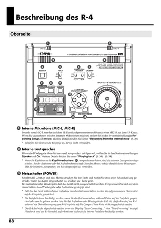


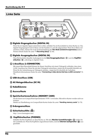

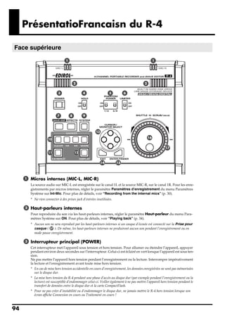
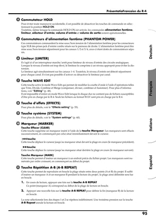


This owner's manual provides important safety information and instructions for operating the unit. The user should read the entire manual carefully before use to ensure safe and proper use of all features. The manual should be saved for future reference.


