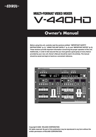
This owner's manual provides important safety instructions and information about operating the unit. Users should read the entire manual, especially the sections on safety instructions, before use. The manual should be saved for future reference. The unit requires proper care and maintenance to avoid damage, malfunctions, or loss of data.


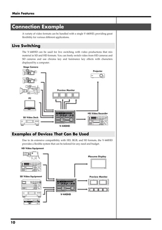


![Connections and Settings
Making the Connections
921 To prevent malfunction and/or damage to speakers or other devices, always turn
down the volume, and turn off the power on all devices before making any
connections. HD/RGB IN Connectors
(Analog Component/RGB)
1 Make sure that the component Y, Pb,
Before connecting the V-440HD, make sure that the power to all devices to be and Pr are properly connected when
connecting component video to the
connected is turned off.
HD/RGB IN BNC connectors. If
connecting RGB video, connect R, G,
2 B, H, and V. Failure to connect these
Connect the included power cord to the V-440HD’s AC inlet, then connect the properly may prevent output of the
other end of the cord to a power outlet. video or result in problems with the
colors.
3 Connect the V-440HD to other devices as shown in the figure.
MIDI Device RS-232C Device
[V-440HD Connecting Diagram]
MIDI Sequencer PC or Other Device
MIDI Cable
RS-232C Cable
HD Video Output Device RGB Video Output Device SD Video Output Device
HD Camera PC or Other Device DV Camcoder , Presenter
D-Sub Cable
Component
Composite
Cable
Cable
Loop Thru
AC Cable
D-Sub Cable
D-Sub Cable
Component Cable
VGA Cable
Component-D-Sub Cable
D-Sub Cable
Component-
Composite Cable
Composite
Cable
Ground terminal
to Concent
Composite Cable
Final Output (HD) VGA Monitor SD PREVIEW Monitor
Plasma Display or Other Display VGA Display TV Monitor or Other Device
Final Output (RGB) HD IN Monitor SD PGM OUT Monitor SD IN Monitor
Projector or Other Display Multiformat Monitor or Other Device TV Monitor or Other Device TV Monitor or Other Device
external ground
20](https://image.slidesharecdn.com/v-440hdre2-091221141526-phpapp02/85/V-440-Hd-R-E2-20-320.jpg)


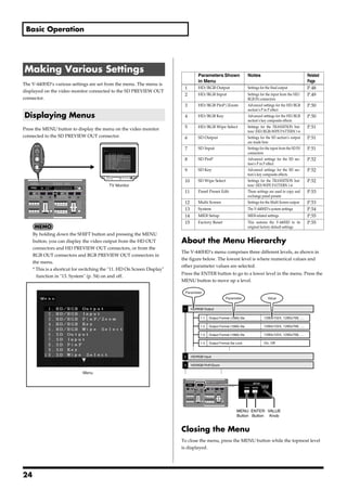

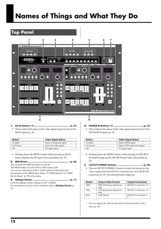
![Input and Output Settings
Since the V-440HD is capable of handling video input and output
with entirely different formats, it may be necessary to make
adjustments for the differences in picture quality and angle of view
Making the Output Settings
in each video format. To match the device used for inputting video The output settings are made from the menu. The menu is displayed
to the V-440HD to the device receiving the output from the V- in the SD video output from the SD PREVIEW OUT connector.
440HD, make the input and output settings.
* For more on the menus, refer to Menu Operations (p. 25).
* To rapidly get to the output settings menu, hold down the MENU
Selecting the Output Format button and press one of the OUTPUT FORMAT buttons.
Press an OUTPUT FORMAT button to select the format for the video
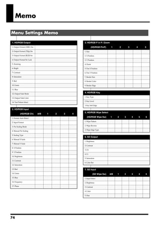
1. HD/RGB Output Settings Parameters
output from the HD OUT connectors (p. 19) or RGB OUT connectors
Output Format (1080i ) Sw (1080i) video format
(p. 19). The selected button lights up. Output Format (720p) Sw (720p) video format
Output Format (RGB) Sw (RGB) video format
Output Format Sw Lock OUTPUT FORMAT button lock
Zooming Final output scaling adjustment
Bright Final output brightness adjustment
Contrast Final output contrast adjustment
Saturation Final output saturation adjustment
Red Final output red adjustment
Green Final output green adjustment
Button Output Format Output Connectors
Blue Final output blue adjustment
(Factory Default (Factory Preset Setting)
Setting) Output Fade Mode Final output fade control adjustment
Output Fade Color Final output fade color setting
1080i 1080/60i HD OUT Connectors 1, 2 (not
output from RGB OUT con- Test Pattern Select Test pattern output
nectors 1, 2)
720p 720/60p HD OUT Connectors 1, 2 (not
output from RGB OUT con-
About the Output Format
nectors 1, 2) The V-440HD handles output in the following formats
RGB 1024x768/60 RGB OUT Connectors 1, 2
[HD OUT]
(not output from HD OUT
connectors 1, 2) The HD output formats feature frame rate settings of 60 and 50. The
frame rate used in the United States and Japan (NTSC regions) is 60;
* The formats shown above are the default factory settings. You can also
in Europe (PAL regions), the frame rate is 50. The frame rate can be
select output formats other than these. For more details, refer to
switched using the procedure described on p. 42.
About the Final Output Format (p. 48).
60 - NTSC 50 - PAL
1080/60i 1080/50i
720/60p 720/50p
Start with the Output Settings 480/60p 576/50p
When making these settings, start by making the output 480/60i 576/50i
settings first. Setting the output after making the input settings [RGB OUT]
will result in discrepancies in the color and angle of view if the 1280x1024/60 1024x768/60 640x480/75
input video is switched to a format other than those used in the 1280x1024/60 1024x768/75 640x480/60
output settings. 1280x768/75 800x600/75
1280x768/60 800x600/60
* Units: [horizontal (pixels) x vertical (lines) / frame rate (Hertz)].
About Delayed Output
Note that, due to the process of up-converting and down- About NTSC and PAL SD Output
converting processes, the use of multiple formats with the V-
Either NTSC or PAL can be selected for the SD section's input and
440HD will result in a lag of several frames.
output. For instructions on making the settings, refer to Switching
[Approximate Delays] Between NTSC and PAL (p. 42). Additionally, the HD OUT output
Input/Output SD PGM Out HD Out / RGB Out format frame rate is determined by the format set here.
SD Input 1 frame 2 frames
HD/RGB Input --- 1 frame
These delays may cause discrepancies in the timing of the
external audio and the video processed by the V-440HD. In
such a case you might use an audio delay line in order to
synchronize the video and audio.
26](https://image.slidesharecdn.com/v-440hdre2-091221141526-phpapp02/85/V-440-Hd-R-E2-26-320.jpg)
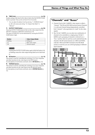
![Input and Output Settings
Setting the HD/RGB Input Setting the SD Input
With the HD/RGB inputs, the image’s dimensions and color may Although the SD input is in a fixed format, there may be differences
vary with each individual format and/or device, so it may be in the type of device used or physical differences, and it may be
necessary to make separate settings for each input individually. necessary to set each input individually.
The default factory setting for the HD/RGB input format is
“AUTO,” whereby the settings are determined automatically.
Settings
Settings Make the SD video settings in the menu with "7. SD Input." In "7. SD
Input," you can select from the SD Channel 1-4, and make settings
Make the HD/RGB video settings with "2. HD/RGB Input" in the the parameters listed below.
menu. With "2. HD/RGB Input," you can select from the HD/RGB
Channel A/B and 1-4, and set the following parameters.
* For more on the menus, refer to Menu Operations (p. 25).
* To quickly go to the Input settings menu, hold down the MENU
* To quickly go to the input settings menu, hold the MENU button and
button and press any of the SD IN buttons 1-4.
Press any of the HD/RGB Buttons 1-4.
* For more on the menus, refer to Menu Operations (p. 25).
7. SD Input Settings Parameters
2. HD/RGB Input Settings Parameters SD InputSelect Selects S-Video or component for the SD input
Format Auto Detect Function automatically distinguishes input SD Brightness Brightness adjustment
Input Format Input format select SD Contrast Contrast adjustment
Pre Scaling Mode Switches scaling adjustment function on and off SD Saturation Saturation adjustment
Manual Pre Scaling Adjusts scaling ratio when full scaling used SD Hue Hue adjustment
Scaling Type Scaling method
Manual X Scale Adjusts the horizontal expansion ratio
Manual Y Scale Adjusts the vertical expansion ratio About SD Input
X Position Fine adjustment of the horizontal start position
Y Position Fine adjustment of the vertical start position The V-440HD is compatible with the following SD signal formats.
Brightness Brightness adjustment • NTSC 59.94 Hz Component video format
Contrast Contrast adjustment
S-Video format
Saturation Saturation adjustment
Red Red adjustment • PAL 50 Hz Component video format
Green Green adjustment S-Video format
Blue Blue adjustment
Frequency Fine adjustment of the Sampling Frequency
Phase Fine adjustment of the Sampling Phase Select either NTSC or PAL for use with the V-440HD. For
instructions on setting the SD signal format to be used, refer to
About HD Input Switching Between NTSC and PAL (p. 42)
The V-440HD is compatible with the following HD signal formats.
• 1080 59.94i / 50i : (SMPTE 274M)
• 720 59.94p / 50p : (SMPTE 296M) Inputting Analog Component SD Video
About RGB Input To input SD video to the V-440HD as analog component video,
The V-440HD is compatible with the following RGB signal formats. input to the HD/RGB IN BNC connectors. In this case, the input
• 640x480 60 / 75Hz SD video is handled in the HD/RGB section.
• 800x600 60 / 75Hz With analog component input, no interlace to progressive
• 1024x768 60 / 70 / 75Hz conversion is performed. We recommend that a progressive
• 1280x768 60 / 75Hz signal (480p/576p) be employed for the SD video input.
• 1280x1024 60Hz
* Units: [horizontal (pixels) x vertical (lines) / frame rate (Hertz)].
* Certain signal conditions may produce differences in the aspect ratio
and position of the RGB input. If this occurs, make adjustments with
the "X position," "Y position," "Frequency," "Phase" or other
relevant settings from the menu.
27](https://image.slidesharecdn.com/v-440hdre2-091221141526-phpapp02/85/V-440-Hd-R-E2-27-320.jpg)
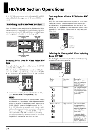
![HD/RGB Section Operations
Selecting the Bus Input (HD/RGB)
The video used on the C-BUS is selected by pressing the C-BUS
channel buttons (HD/RGB) 1-4 and A/B button. In the same
Customizing Wipe Transitions
manner, the video used on the D-BUS is selected by pressing the D- The wipe switching effects assigned to the TRANSITION
BUS channel buttons (HD/RGB) 1-4 and A/B button. (HD/RGB) WIPE PATTERN 1-6 buttons can be set from the
menu. You can make settings for the wipe pattern, direction,
and soft edge, and combine these settings in various ways to
create customized wipe transitions.
* For more on the menus, refer to Menu Operations (p. 25).
* When key composite effect (p. 32) in use, you can not use the
soft edge.
Wipe Patterns
Horizontal
When switching channels with the C-BUS channel buttons Vertical
(HD/RGB) and D-BUS channel buttons (HD/RGB), several
frames is required to switch the video in each bus. This is due to
the time required to lock the video signals when switching the
video input formats used in each channel. To shorten the Horizontal Open
duration, select the following parameter from the menu and
adjust the parameter.
* When you need to switch between Buses quickly, use the Vertical Open
Video Fader (HD/RGB) (p. 28)
* With some settings, noise may occur when the video is
switched. Set a value that provides sufficient time for
switching to avoid this problem. Box
• "HD/RGB Input" - (Each channel)
[1. Format Auto Detect]
If "Auto" is set, set this to "Manual" and then select the Cross
format for the video being input.
[2. Input Format]
Select the format for the video being input.
• "13. System"
[9. HD Seamless Delay Time]
Keep the time setting somewhat short. The unit of time is
the field.
29](https://image.slidesharecdn.com/v-440hdre2-091221141526-phpapp02/85/V-440-Hd-R-E2-29-320.jpg)
![HD/RGB Section Operations
* Use of the C-BUS channel buttons (HD/RGB) (or D-BUS channel
buttons (HD/RGB)) while combining video with the P in P effect may
HD/RGB Section P in P Effects result in disruption of the video image.
P in P (Picture in Picture) effects are applied to the video on the C- * Wipe Patterns 1-6 cannot be selected with the "TRANSITION
BUS or D-BUS. The video on the bus to which the P in P effect is buttons (HD/RGB)" (p. 28) while the P in P effect is in use.
applied appears as a smaller sub-screen displayed in reduced size
over the video on the other bus.
Background Insert Terminology Used with the P in P Effect
The following terminology is used in describing the V-440HD’s
P in P effect.
• Position: positioning of the sub-screen
• Size: size of the sub-screen
• Zoom: Magnification of the video in the sub-screen (HD/
RGB only)
• Pan: Positioning of the video within the sub-screen (HD/
RGB only)
[Position - Size]
Procedure for Setting the HD/RGB Section P in P Effect
1 3 2, 4
Position Size
[Zoom - Pan] Zoom
1. Select the video to include in the sub-screen with the C-
BUS channel buttons (HD/RGB) (or D-BUS channel buttons
(HD/RGB)).
2. Tilt the video fader (HD/RGB) to the opposite side from that
of the bus selected in Step 1. Use of zoom/pan does not change the
position or size of the sub-screen.
3. Press a P in P PATTERN button (HD/RGB).
The button or buttons pressed in Step 1 flash. At this point, a button
flashing indicates that the P in P effect is being applied to the video
assigned to that button.
Button Sub-Screen Position (Factory Setting)
Upper left
1 Pan
Upper right
2
Lower right
3
Lower left
4
Center
5
4. Tilt the video fader (HD/RGB) to the opposite direction.
The video assigned to the channels corresponding to the flashing
buttons in Step 3 appears as the sub-screen.
* When key composite effects are in use, the P in P effect is applied to the
selected bus, regardless of the video fader (HD/RGB) position.
30](https://image.slidesharecdn.com/v-440hdre2-091221141526-phpapp02/85/V-440-Hd-R-E2-30-320.jpg)


![SD Section Operations
Selecting the Bus Input
The video used on the A-BUS is selected by pressing the A-BUS SD Section P in P Effects
channel buttons (SD) 1-4. In the same manner, the video used on the
P in P (Picture in Picture) effects are applied to the video on the A-
B-BUS is selected by pressing the B-BUS channel buttons (SD) 1-4.
BUS or B-BUS. The P in P effect is used just by pressing the P in P
PATTERN buttons (SD).
Background Insert
When switching channels with the A-BUS channel buttons (SD) Procedure for Setting the SD Section P in P Effect
and B-BUS channel buttons (SD), several frames is required to
1 3 2, 4
switch the video in each bus. This is due to the time required to
lock the video signals when switching the video input formats
used in each channel. To shorten the duration, select the
following parameter from the menu and adjust the parameter.
* When you need to switch between Buses quickly, use the,
use Video Fader (SD) (p. 34)
* With some settings, noise may occur when the video is
switched. Set a value that provides sufficient time for
switching to avoid this problem.
• "13. System" - [10. SD Seamless Delay Time] 1. Select the video to include in the sub-screen with the A-
Keep the time setting somewhat short. The unit of time is BUS channel buttons (SD) (or B-BUS channel buttons (SD)).
the field.
2. Tilt the video fader (SD) to the opposite side from that of the
bus selected in Step 1.
Customizing the Wipe 3. Press a P in P PATTERN button (SD).
The button or buttons pressed in Step 1 flash. At this point, a button
The wipe switching effects assigned to the TRANSITION (SD)
flashing indicates that the P in P effect is being applied to the video
WIPE PATTERN 1-6 buttons can be set from the menu. You can
assigned to that button.
make settings for the wipe pattern, direction, and soft edge, and
combine these settings in various ways to create customized Button Sub-Screen Position (Factory Setting)
wipe transitions. Upper left
1
* For more on the menus, refer to Menu Operations (p. 25). Upper right
2
* For more information about the different kinds of wipe patterns,
Lower right
refer to "Customizing Wipe Transitions"(p. 29) 3
Lower left
4
Center
5
4. Tilt the video fader (SD) to the opposite direction.
The video assigned to the channels corresponding to the flashing
buttons in Step 3 appears as the sub-screen.
* When using the P in P effect while a key composite effect is in use, the
P in P is applied to the video with the key effect settings included.
* Use of the A-BUS channel buttons (SD) (or B-BUS channel buttons
(SD)) while combining video with the P in P effect may result in
disruption of the video image.
* Wipe Patterns 1-6 cannot be selected with the "TRANSITION
buttons (SD)" (p. 34) while the P in P effect is in use.
35](https://image.slidesharecdn.com/v-440hdre2-091221141526-phpapp02/85/V-440-Hd-R-E2-35-320.jpg)


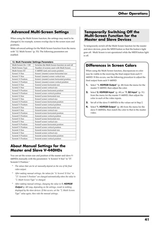
![Other Operations
Exchanging Presets Multi-Screen Output
Use the following procedure to exchange settings stored in one With MIDI used to link multiple V-440HDs, you can then use the
PANEL PRESET with settings stored at another PANEL PRESET “multiscreen output,” whereby the video is partitioned and output
button. to multiple screens. With “multiscreen output,” one V-440HD is
used for control, with the operation of other V-440HDs synchronized
1. Press the MENU button.
to it.
The menu is displayed.
[Connecting Diagram]
2. Select "11. Panel Preset Edit."
3. Select "2. Exchange."
4. Select the preset to be exchanged.
The preset shown at the left of the screen becomes the exchange Output Output Output
source. Video Video
5. Press the ENTER button.
MIDI MIDI
6. Select the preset exchange destination. Master Slave1 Slave2
7. Press the ENTER button. * The V-440HD used as the control device is referred to here as the
The message "Are You Sure?" appears. “master.” The other V-440HDs whose operations are synchronized to
the master are referred to as “slaves.”
8. Select "Yes."
9. Press the ENTER button.
The preset shown at the left of the screen is exchanged with the
Connection Instructions for Multi-Screen Output
preset stored to the PANEL PRESET button selected in Step 6. When using multiscreen output, use the following method to
connect the V-440HD with other devices.
* When making any connections, always be sure to turn off the power to
all devices before connecting them.
Connecting When Two Screens Are Used
When using multiscreen output with two screens, connect the master
and the slave directly to each other.
[Connecting Diagram]
[HD/RGB] [SD]
Component - D-sub
MIDI
Composite - Video
Master
Loop Through
Slave
1. Distribute the video.
When using multiscreen output with two screens, use loop thru to
distribute the video from the HD/RGB input to the two V-440HDs
(p. 21).
* When using loop thru, set the HD/RGB 75Ω TERMINATOR switch
to OFF.
39](https://image.slidesharecdn.com/v-440hdre2-091221141526-phpapp02/85/V-440-Hd-R-E2-39-320.jpg)
![Other Operations
2. Connect via MIDI.
Using a MIDI cable, connect the master V-440HD’s MIDI OUT/
THRU connector to the MIDI IN connector on the slave V-440HD.
Making the Multi-Screen Settings
3. Connect the screens. After connecting the devices according to the procedures described
Connect the left screen to the master V-440HD’s HD OUT or RGB on p. 39 and p. 40, make the V-440HD settings. Set all of the V-
connectors. 440HDs as described below.
Connect the right screen to the slaved V-440HD’s HD OUT or RGB 1. Press the MENU button.
connectors.
2. Select "12. Multi Screen."
Connecting When Three or More 3. Set "2. Multi Screen Mode."
Screens Are Used Select the screen layout. The master and slave values are set
automatically.
Using multiscreen output with three or more screens requires use of
* For more on the screen position, refer to "Slave Numbers and Screen
to distribute the video and MIDI signals for the master and multiple
Positions."
connected slaves.
* Satisfactory image quality may not be obtainable using loop thru to 4. 4. Set "3. Multi Screen ID."
distribute the video to three or more V-440HD. This sets the screen positions for the master and slave V-440HDs.
[Connecting Diagram] Referring to "Slave Numbers and Screen Positions" below, make
selections from Screen1-Master to Screen6-Slave. Assign Screen1-
HD
Distributer Master to the V-440HD corresponding to the highest priority MIDI
[HD]
signal (the uppermost unit in the right figure on p. 40). V-440HDs set
to Screen2-Slave to Screen6-Slave become slave devices.
MIDI
Master * For more on the MIDI setting, refer to Controlling the V-440HD
from an External Device Via MIDI and Linking Operations
RGB
Distributer Via MIDI (p. 45).
[RGB]
Turning the Multi Screen Function On
MIDI
Slave1
1. Select "On" for the master V-440HD's "1. Multi Screen On/Off" setting.
SD After making the settings in Steps 1-4 of "Making the Multi Screen
Distributer
[SD] Function Settings" for all of the V-440HDs, select "On" in "1. Multi
Screen On/Off" under "12. Multi Screen" in the menu for the master
Slave2
V-440HD. The Multi Screen function is switched on, and each V-
1. Distribute the video. 440HD displays the video corresponding to its assigned screen
When using multiscreen output with three or more screens, use to position.
distribute the video to each input.
* Use an interface compatible with the format of the video being Turning the Multi Screen Function Off
distributed.
Select "Of" in "1. Multi Screen On/Off" under "12. Multi Screen" in
* Make sure that the same type of video signals are input to each V- the menu for the master V-440HD.
440HD. If, for example, you are grouping S-Video signals in SD IN
Channel 4, make sure that the signal formats are the same, even
though the video may have the same field of view.
Position of screen Position of screen
2. Connect via MIDI. 2x1 3x1
Use a MIDI cable to connect the MIDI OUT/THRU connector on the
master V-440HD to the MIDI IN connector on the slave V-440HD. 1 2 1 2 3
Connect any additional V-440HDs in the same manner.
* If connecting multiple V-440HDs results in attenuation of the
operational signals, use a MIDI interface (e.g., Edirol UM-880) to 2x2 3x2
multiplex the MIDI output signals from the master V-440HD. 1 2 1 2 3
4 5 6
3. Connect the screens. 3 4
Send the video output from the master and slaves as shown in the
table. Connect the master and slave HD OUT or RGB outputs to the
* Numbers in the figure indicate slave order.
corresponding video output devices.
40](https://image.slidesharecdn.com/v-440hdre2-091221141526-phpapp02/85/V-440-Hd-R-E2-40-320.jpg)


![Reference
MIDI Connectors
Controlling the V-440HD from an The following three types of connectors are used in exchanging MIDI
External Device Via MIDI messages (data handled with MIDI). On the V-440HD, the MIDI
OUT and MIDI THRU are combined in one connector. The function
is switched according to the operation being performed.
The V-440HD can be controlled from an external device using MIDI.
For example, you can use a Roland multitrack recorder to control MIDI IN: MIDI messages from other MIDI devices are received here.
video performances that are synchronized to the sounds. MIDI OUT: MIDI messages from the V-440HD are transmitted from
This section explains some basics of MIDI and describes the use of here. MIDI THRU: MIDI messages received at the MIDI IN
MIDI messages with the V-440HD. connector are output as is.
What is MIDI? Linking Operations Via MIDI
MIDI, an abbreviation for Musical Instrument Digital Interface, is an You can use MIDI to link the operation of multiple V-440HDs. To do
international standard created to enable exchange of performance so, make the following settings.
data among devices. Any MIDI-compatible device can be connected • Linking operation of multiple V-440HDs
simply with a MIDI cable, allowing transfer of performance data and Select "14. MIDI Setup" (p. 55) from the menu and set "4. MIDI
control of device operations and settings. Out/Thru Switch" to "Thru."
• Linking operation using "Multi-Screen Output" (p. 39)
For instructions on linking operation of multiple V-440HDs with
Controlling the V-440HD from an External Device Via MIDI the Multi-Screen function, refer to "Multi-Screen Output" (p. 39).
After switching on the power (when V-LINK is off), MIDI messages are
output from MIDI OUT in response to adjustments with the corresponding
Temporarily Switching Off Linked Operation
buttons and knobs. In addition, adjustments identical to those made with the You can stop reception of MIDI signals temporarily by pressing the
buttons and knobs are made when the corresponding MIDI messages are MIDI button. This stops linked operation via MIDI and enables
received at MIDI IN. independent functioning of one individual V-440HD.
* For more about MIDI messages, refer to the "MIDI implementation (p. To restore linked operation through MIDI, press the MIDI button
59). once more so the button is lit.
PANEL PRESET Button
[Things that receives MIDI message] 2
1 MIDI Button 3 OUTPUT FORMAT Button
4 TIME Knob
3
1 2 4 5 5 OUTPUT FADE Button
6 7 8 18 19 20 21
9 10 11 12 22 23 24 25
13 15 16 26 28 29
14 17 27 30
6 POSITION Joystick (SD) 12 TIME Knob (SD) 18 POSITION/SIZE Button (HD/RGB) 24 KEY ON Button (HD/RGB)
PAN/ZOOM Button (HD/RGB)
7 LOCK Button (SD) 13 A-BUS Channel Button (SD) 25 TIME Knob (HD/RGB)
19 POSITION/PAN Joystick (HD/RGB)
8 SIZE Knob (SD) 14 B-BUS Channel Button (SD) 26 C-BUS Channel Button (HD/RGB)
20 LOCK Button (HD/RGB)
9 P in P PATTERN Button (SD) 15 Video Fader (SD) 27 D-BUS Channel Button (HD/RGB)
21 SIZE/ZOOM Knob (HD/RGB)
10 LEVEL Knob (SD) 16 TRANSITION Button (SD) 28 Video Fader (HD/RGB)
22 P in P PATTERN Button (HD/RGB)
11 KEY ON Button (SD) 17 AUTO Button (SD) 29 TRANSITION Button (HD/RGB)
23 LEVEL Knob (HD/RGB)
30 AUTO Button (HD/RGB)
45](https://image.slidesharecdn.com/v-440hdre2-091221141526-phpapp02/85/V-440-Hd-R-E2-45-320.jpg)
![Reference
MIDI Messages Handled by the V- Control Using V-LINK
440HD
You can have control of the V-440HD be linked to the performance
The following MIDI messages are handled with the V-440HD. of a V-LINK compatible instrument (when V-LINK is on)
What is V-LINK?
• Bank Select and Program Change
V-LINK ( ) is the name of a feature that makes it possible to
These messages are used for switching tones. On the V-440HD, Bank
use MIDI to control visual presentations that are designed to
Select messages are used to select the bus, and Program Change
accompany a musical performance. Thanks to V-LINK, it’s easy to
messages are used to select channels.
present a variety of video linked to the expressive elements of a
performance.
• Control Change Messages
With V-LINK, you can use Roland and Edirol instruments and music
These generally transmit information, such as vibrato, hold, and
devices to control the video without any degradation in the
volume, that enhances the realism of performances. All functions are
instruments’ original functions (producing sounds).
organized according to a controller number from 0 to 127, with each
function being assigned its own number. On the V-440HD, these
messages are used with the video faders and knobs. Instructions for Using V-LINK
@p
For information on switching V-LINK on and off, refer to the
• System Exclusive Messages
Owner’s Manual for the V-LINK compatible device to be connected
These messages are used for transmitting device-specific settings.
to the V-440HD.
On the V-440HD, these messages are used for transmitting P in P
settings and when setting the Multi Screen outputs. * You can confirm the V-LINK MODE status by checking whether or
not the MIDI button is lit. Select "14. MIDI setup"(p. 55) from the
When System Exclusive messages are exchanged, MIDI
menu and set “MIDI Sw Mode” to “V-Link Indicator“.
transmissions are distinguished by Device IDs rather than MIDI
channels. When exchanging System Exclusive messages, set the * To see which functions can be controlled from an external device with
devices to the same Device ID. V-LINK, refer to the MIDI Implementation on p. 66 as well as the
MIDI Implementation for the device being connected. The functions
that can be controlled may vary according to the device being
MIDI channels connected and the settings.
MIDI is able to send information over a single MIDI cable Initial V-LINK Status Settings (V-440HD
independently to two or more MIDI devices. This is made possible
Receives Only the V-LINK ON Message)
by the concept of MIDI channels. You can think of MIDI channels as
being somewhat similar in function to the channels on a television. Rx Channel 1
By changing the channel of a TV set, you can view a variety of Tx Channel 1
programs being transmitted by different broadcast stations. This is SD A Bus Ach:1
because data is received only from the transmitter whose channel is SD B Bus Bch:2
SD Auto Switch -
selected on the receiver.
SD Transition Pattern Mix
In the same way, a MIDI device whose receive channel is set to [1] SD Transition Time 0.0sec
will receive only the data being transmitted by another MIDI device SD Video Fader Ach100%
whose transmit channel is also set to [1.] SD Key Switch OFF
SD PinP Switch OFF
SD PinP Lock Switch OFF
HD C Bus Cch:1
MIDI Implementation Chart HD D Bus Dch:2
The use of MIDI makes it possible to communicate with a broad HD Auto Switch -
range of electronic musical instruments. However, this does not HD Transition Pattern Mix
HD Transition Time 0.0sec
mean that all MIDI messages can be exchanged among all devices.
HD Video Fader Cch100%
Only those MIDI messages that both of the communicating devices
HD Key Switch OFF
are designed to understand can be exchanged. The owner’s manual HD PinP Switch OFF
that comes with a MIDI device includes a MIDI Implementation HD PinP Lock Switch OFF
Chart (p. 66). Such charts allow you to easily find out which MIDI PinP/Zoom Switch PinP
messages that device can transmit and receive. When using MIDI Panel Preset Switch OFF
devices, compare the charts for the devices that will be Output Format Switch 1
Output Fade Mode Auto
communicating to check which MIDI messages are compatible.
Fade Switch -
Fade Level MAX
46](https://image.slidesharecdn.com/v-440hdre2-091221141526-phpapp02/85/V-440-Hd-R-E2-46-320.jpg)

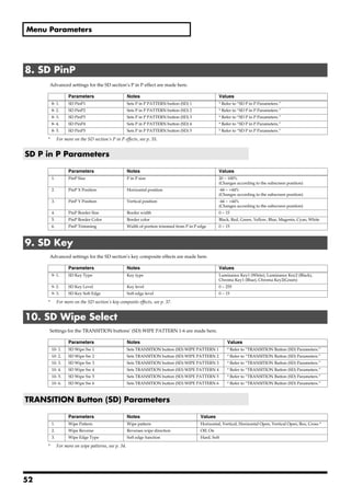
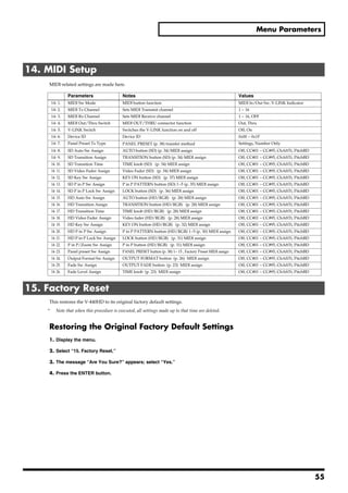
![Menu Parameters
* For more on menus, see p. 24.
1. HD/RGB Output
Settings for the final output are made here.
Parameters Notes Values
1- 1. Output Format (1080i) Sw (1080i) video format Refer to “About the Final Output Format.”
1- 2. Output Format (720p) Sw (720p) video format Refer to “About the Final Output Format.”
1- 3. Output Format (RGB) Sw (RGB) video format Refer to “About the Final Output Format.”
1- 4. Output Format Sw Lock OUTPUT FORMAT button lock Off, On
1- 5. Zooming Final output scaling adjustment 80.0 ~ 120.0
1- 6. Bright Final output brightness adjustment -64 ~ +64
1- 7. Contrast Final output contrast adjustment -64 ~ +64
1- 8. Saturation Final output saturation adjustment -64 ~ +64
1- 9. Red Final output red adjustment -64 ~ +64
1- 10. Green Final output green adjustment -64 ~ +64
1- 11. Blue Final output blue adjustment -64 ~ +64
1- 12. Output Fade Mode Final output fade control adjustment Auto, Manual
Refer to “About the Final Output Fade Control”
1- 13. Output Fade Color Final output fade color setting Black, White
1- 14. Test Pattern Select Test pattern output Off, 75% Color Bar, 100% Color Bar
About the Final Output Format
You can select from the following formats for use with the final output.
Component RGB
1080i (50/60) 1280x1024/60
720p (50/60) 1280x768/75
480p (50/60) 1280x768/60
480i (50/60) 1024x768/75
1024x768/60
800x600/75
800x600/60
640x480/75
640x480/60
* Numbers in parentheses for the component formats indicate frame rate. Frame rates for parameters with (50/60) can be set with the value in “1.
System Frame Rate” under “13. System.”
* Units are [horizontal (pixels) x vertical (lines) / frame rate (Hertz)].
About the Final Output Fade Control
There are two final output fade modes (p. 23), which can be changed as needed.
[1-12. Output Fade Mode Settings and Function of Each Controller]
Auto Manual
OUTPUT FADE Button Fades in/out according to value set with TIME knob -(Flashes when video is fading out)
TIME Knob Sets Fade-in/Fade-out time for final output Controls fade-in/fade-out time
48](https://image.slidesharecdn.com/v-440hdre2-091221141526-phpapp02/85/V-440-Hd-R-E2-48-320.jpg)
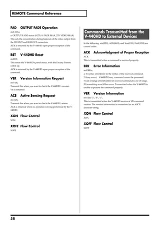
![Menu Parameters
2. HD/RGB Input
Settings for the input from the HD/RGB IN connectors are made here.
Parameters Notes Values
2- 1. HD/RGB Ch A/B Sets input for SD section video input to HD/RGB * Refer to “HD/RGB Input Parameters.”
2- 2. HD/RGB Ch 1 Sets video input to Channel 1 of the HD/RGB IN connectors * Refer to “HD/RGB Input Parameters.”
2- 3. HD/RGB Ch 2 Sets video input to Channel 2 of the HD/RGB IN connectors * Refer to “HD/RGB Input Parameters.”
2- 4. HD/RGB Ch 3 Sets video input to Channel 3 of the HD/RGB IN connectors * Refer to “HD/RGB Input Parameters.”
2- 4. HD/RGB Ch 4 Sets video input to Channel 4 of the HD/RGB IN connectors * Refer to “HD/RGB Input Parameters.”
HD/RGB Input Parameters
Parameters Notes Values
1. Format Auto Detect Function automatically distinguishes input *1 Auto, Manual
2. Input Format Input format select *1*2 * Refer to “About the HD/RGB Input Format”
3. Pre Scaling Mode Switches scaling adjustment function on and off Auto, Manual
4. Manual Pre Scaling Adjusts scaling ratio when full scaling used *3 90.0 ~ 110.0%, Auto
5. Scaling Type Scaling method Full Scale. Fixed Aspect: Letter, Fixed Aspect:Crop, Manual
6. Manual X Scale Adjusts the horizontal expansion ratio *4 0010 ~ +1000
7. Manual Y Scale Adjusts the vertical expansion ratio *4 0010 ~ +1000
8. X Position Fine adjustment of the horizontal start position -64 ~ +64
9. Y Position Fine adjustment of the vertical start position -64 ~ +64
10. Brightness Brightness adjustment -64 ~ +64
11. Contrast Contrast adjustment -64 ~ +64
12. Saturation Saturation adjustment -64 ~ +64
13. Red Red adjustment -64 ~ +64
14. Green Green adjustment -64 ~ +64
15. Blue Blue adjustment -64 ~ +64
16. Frequency Fine adjustment of the Sampling Frequency *1 -64 ~ +64
17. Phase Fine adjustment of the Sampling Phase *1 -64 ~ +64
*1 Cannot be set in HD/RGB Channel A/B. Parameter numbers are in sequence, with these parameters omitted.
*2 Enabled when Format Auto Detect is set to Manual.
*3 Enabled when Pre Scaling Mode is set to Manual.
*4 Enabled when Scaling Type is set to Manual.
About the HD/RGB Input Format
The V-440HD inputs component and RGB video in the formats shown in the following table.
Component RGB
480/60p 640x480/60
576/50p 640x480/75
1080/60i 800x600/60
1080/50i 800x600/75
720/60p 1024x768/60
720/50p 1024x768/75
1280x768/60
1280x768/75
1280x1024/60
* RGB units are [horizontal (pixels) x vertical (lines) / frame rate (Hertz)].
49](https://image.slidesharecdn.com/v-440hdre2-091221141526-phpapp02/85/V-440-Hd-R-E2-49-320.jpg)


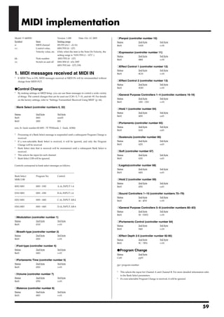
![Menu Parameters
13. System
The V-440HD’s system settings are made here.
Parameters Notes Values
13- 1. System Frame Rate Switches between NTSC and PAL 60 - NTSC, 50 - PAL
13- 2. SD Deinterlacer SD section I/P conversion function Off, On
13- 3. SD Input Sync Threshold SD input sync level adjustment -64 ~ +64
13- 4. SD V-FdrCaribrate A SD video fader adjustment * Refer to “Adjusting the Video Faders.”
13- 5. SD V-FdrCaribrate B SD video fader adjustment * Refer to “Adjusting the Video Faders.”
13- 6. HD/RGB V-FdrCaribrate C HD/RGB video fader adjustment * Refer to “Adjusting the Video Faders.”
13- 7. HD/RGB V-FdrCaribrate D HD/RGB video fader adjustment * Refer to “Adjusting the Video Faders.”
13- 8. REMOTE Baudrate REMOTE bit rate setting 9600bps, 19200bps
13- 9. HD Seamless Delay Time Delay time when C-BUS (D-BUS) channel buttons are 0 ~ 50 (Field)
used
13- 10. SD Seamless Delay Time Delay time when A-BUS (B-BUS) channel buttons are 0 ~ 50 (Field)
used
13- 11. HD On Screen Display Displays HD/RGB output in menu On, Off
13- 12. Tally Signal Mode for signals output from TALLY terminals Type1, Type2, Type3
13- 13. SD Previewout Select Video output from SD PREVIEW OUT connector Preview Out, PGM Out
13- 14. Memory Protect Memory Protect function Off, On
Adjusting the SD Input Sync Level
The sync level of the SD signal output by some SD video devices may be lower than standard values, preventing adequate synching
when the V-440HD is set to factory default values. If this occurs, you may be able to achieve synchronization by adjusting the “13-5.
Video Sync Threshold” parameter.
Adjusting the Video Faders
Continued use of the video faders and transport of the V-440HD may make adjustments to the faders necessary. In such cases, use
the following procedure to make the adjustments.
[Adjusting the Video Fader (SD)]
1. Display the menu.
2. Select “4. SD V-Fdr Calibrate A” under “13. System.”
3. Tilt the video fader (SD) to the A-BUS.
4. The message “Are You Sure?” appears; select “Yes.”
5. Select “SD V-Fdr Calibrate B.”
6. Tilt the video fader (SD) to the B-BUS.
7. The message “Are You Sure?” appears; select “Yes.”
* Use the same procedure to adjust the video fader (HD/RGB), using “Video Fader Calibrate C” and “Video Fader Calibrate D.”
54](https://image.slidesharecdn.com/v-440hdre2-091221141526-phpapp02/85/V-440-Hd-R-E2-54-320.jpg)
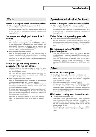
![REMOTE Command Reference
For more information on transmission settings, refer to About the STM TIME Knob (SD) Setting
REMOTE Connector (p. 44).
stxSTM:a;
a: Time (0.0-4.0)
Overview of Commands
ACK is returned by the V-440HD upon proper reception of the
A command consists of an ASCII code sequence containing "stx,"
command.
three uppercase letters of the alphabet, and a semicolon (";"). The
three letters of the alphabet indicate the command type. If the
SAT AUTO Button (SD) Setting
command has an argument, a colon (":") is inserted between the two
stxSAT:a;
letters of the alphabet and the argument. When multiple arguments
a: Time (0.0-4.0)
occur, they are separated by commas (",").
This switches the A-BUS and B-BUS over the time set with the
"stx" This is the ASCII code signal name (code number 02H
number.
[hexadecimal]) and code that signals the command start.
ACK is returned by the V-440HD upon proper reception of the
":" This is the code used by the Presenter to separate the
command.
command and its arguments.
";" This is the code used by the Presenter to signify the end of a
command.
STR TRANSITION Button (SD) Select
stxSTR:a;
Example 1) When transmitting the A-BUS channel select command -
> the ASCII code string stxSIA; is transmitted. a: TRANSITION button (SD) number (0:CUT, 1: MIX 2:WIPE 1, 3:
Example 2) When setting the SD section P in P horizontal placement WIPE 2, 4: WIPE 3, 5: WIPE 4, 6: WIPE 5, 7: WIPE 6)
at 50%, vertical placement at 25%, and size at 50% -> the ASCII code This selects the TRANSITION button (SD) for the effect used in
string stxSPI:50,70,95; is transmitted. switching in the SD section.
ACK is returned by the V-440HD upon proper reception of the
command.
Commands Transmitted from
External Devices to the V-440HD SPS SD Section P in P Effect ON
stxSPS:a;
In the following, stx(02H), ACK(06H), and Xon(11H)/Xoff(13H) are a: P in P status (0-5 (0: OFF, 1-5: P in P PATTERN buttons (SD) 1-5
control codes. ON))
This selects the P in P PATTERN button 1-5 used for the P in P effect
SIA A-BUS Channel Select in the SD section.
stxSIA:a; ACK is returned by the V-440HD upon proper reception of the
a: Channel number (0: SD IN Channel 1, 1: SD IN Channel 2, 2: SD IN command.
Channel 3, 3: SD IN Channel 4)
This selects the A-BUS channels. SPI SD Section P in P Effect Setting
ACK is returned by the V-440HD upon proper reception of the stxSPI:a,b,c;
command. a: P in P horizontal position (%)(-40 to 40)
b: P in P vertical position (%)(-40 to 40)
SIB B-BUS Channel Select c: P in P size (%)(20 to 100)
stxSIB:a; This makes the settings for the P in P currently being displayed.
a: Channel number (0: SD IN Channel 1, 1: SD IN Channel 2, 2: SD IN ACK is returned by the V-440HD upon proper reception of the
Channel 3, 3: SD IN Channel 4) command.
This selects the B-BUS channels.
ACK is returned by the V-440HD upon proper reception of the SKS SD Section Key Composite ON
command. stxSKS:a;
a: Key composite status (0-4 (0: OFF, 1: White Key , 2: Black Key, 3:
STB Video Fader (SD) Position Chroma Key 1, 4: Chroma Key 2))
stxSTB:a; This switches the SD section’s key composite effects on and off. It
a: Video fader (SD) position (0-255, 0: A-BUS, 255: B-BUS) also sets the type of key applied when the effect is switched on.
This sets the video fader (SD) position. ACK is returned by the V-440HD upon proper reception of the
ACK is returned by the V-440HD upon proper reception of the command.
command.
56](https://image.slidesharecdn.com/v-440hdre2-091221141526-phpapp02/85/V-440-Hd-R-E2-56-320.jpg)


![Main specifications
V-440HD: MULTI FORMAT VIDEO MIXER
Video Processing
Video Format: SD NTSC or PAL [CVBS, S (Y/C)]
HD 1080/59.94i/50i SMPTE274M (Y/Pb/Pr TriLevel Sync)
720/59.94p/50p SMPTE296M (Y/Pb/Pr TriLevel Sync)
PC-RGB 640x480/60/75, 800x600/60/75, 1024x768/60/75,1280x768/60/75,
1280x1024/60 (RGB VH:positive/negative logic)
* VESA DMT Version 1.0 Revision 10 conform
Video Sampling Rate: SD 4:2:2 (Y/Cb/Cr) 8-bit 13.5 MHz (BT.601)
HD 4:4:4 (Y/Pb/Pr) 8-bit 74.1758 MHz / 74.25 MHz
RGB 4:4:4 (R/G/B) 8-bit 25 MHz to 110 MHz
Effects Video Transition Cut
Dissolve
Wipe: 6 Patterns, Reverse, SoftEdge
Composition FX Picture in Picture,
Chroma Key (Blue/Green),
Luminance Key(White/Black)
Picture in Picture with Zoom/Pan (HD/RGB side)
Multi-Screen Presentation Screen Setup: 2 screens x 1 line, 3 screens x 1 line, 2 screens x 2 line,
3 screens x 2 lines
Synchronization Multiple Units by MIDI
Master Fade 0 to 4 seconds Black or White
Connectors
SD Input S-Video (Y/C) Preferential x 4: 4 pin mini DIN type (Y: 1.0 Vp-p, C: 0.286 Vp-p, 75 ohms)
Video (composite)x 4 BNC type (1.0 Vp-p, 75 ohms)
HD/RGB Input BNC Type x 4 HD: Y/Pb/Pr (1.0 Vp-p, 75 ohms, TriLevel Sync)
RGB:R/G/B (0.7 Vp-p, 75 ohms), H (5VTTL), V (5VTTL)
D-SUB 15pin Shrink Type x 4 HD: Y/Pb/Pr (1.0 Vp-p, 75 ohms, TriLevel Sync)
* BNC Type or D-sub Type are RGB:R/G/B (0.7 Vp-p, 75 ohms), H (5VTTL), V (5VTTL)
In/ThruOut Use combinedly
SD Output PGM S-Video (Y/C) 4-pin mini DIN type (Y: 1.0 Vp-p, C: 0.286 Vp-p, 75 ohms)
PGM Video (composite) BNC type (1.0 Vp-p, 75 ohms)
Preview BNC type (1.0 Vp-p, 75 ohms), OSD Menu Output
HD Output PGM Component HD BNC Type x 2 (1.0 Vp-p, 75 ohms, TriLevel Sync)
Preview Component HD BNC type (1.0 Vp-p, 75 ohms, TriLevel Sync),
OSD Menu Output (selectable Display)
RGB Output PGM RGB D-sub 15 pin Shrink Type x 2 (0.7 Vp-p, 75 ohms, 5 VTTL Sync)
Preview RGB D-sub 15 pin Shrink type (0.7 Vp-p, 75 ohms, 5 VTTL Sync),
OSD Menu Output (selectable Display)
* Component & RGB Outputs are selectable
Remote Control Interfaces MIDI 5 pin DIN Type (In, Out/Thru)
RS-232C D-sub 9pin
TALLY Output for SD Section D-sub 15 pin Shrink type
Input(max): 12 V, 200 mA Open collector Type
for HD Section D-sub 15 pin Shrink type
Input(max): 12 V, 200 mA Open collector Type
Others
Power Supply AC 117 V, AC 230 V, AC 240 V (50/60 Hz)
AC 220 V (60 Hz)
Power Consumption 50 W
Dimensions 482 (W) x 308 (D) x 130 (H) mm
19 (W) x 12-1/8 (D) x 5-1/8 (H) inches
* EIA-7U Rack Mount Size
Weight 6.8 kg
15 lbs
Accessories Owner’s Manual, Power Cord
* In the interest of product improvement, the specifications and/or appearance of this unit are subject to change without prior notice.
79](https://image.slidesharecdn.com/v-440hdre2-091221141526-phpapp02/85/V-440-Hd-R-E2-79-320.jpg)


