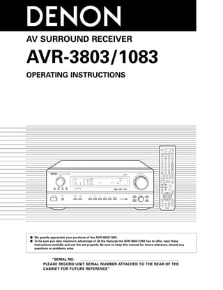
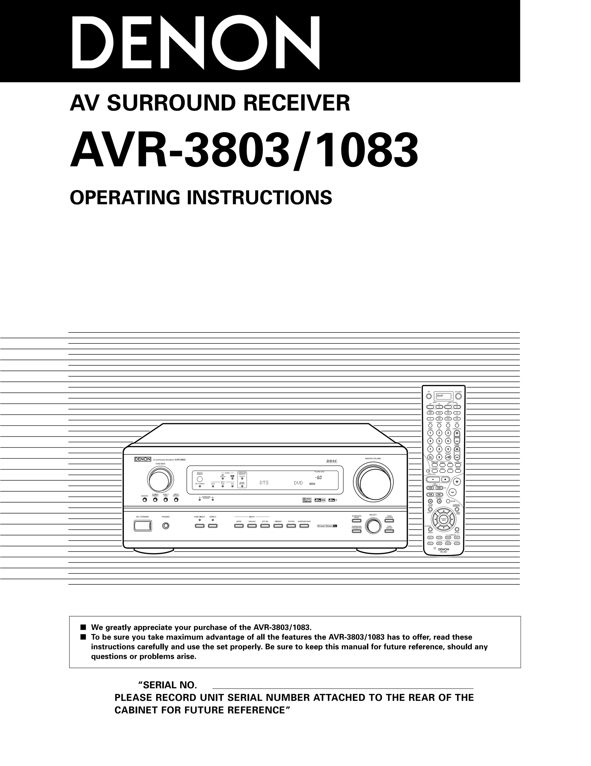
The Denon AVR-3803/1083 is a digital A/V surround receiver designed to deliver high-fidelity surround sound for home theater and music sources. It contains extensive features, including digital surround sound processing, Dolby and DTS decoding capabilities, and multiple audio source options, making it suitable for various listening environments. Proper usage, safety precautions, and detailed operating instructions are provided to ensure optimal performance and safety.
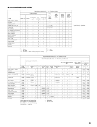
![NOTES:
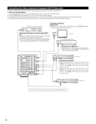
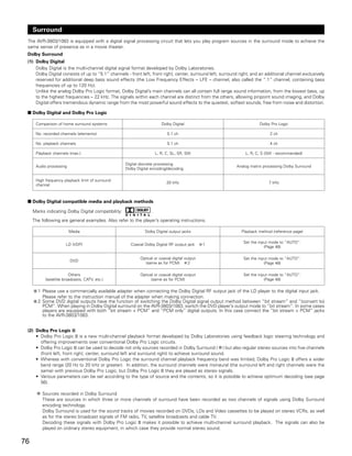
• The OPTICAL 4 and 5 jacks on the AVR-3803/1083’s rear panel are equipped with an optical digital output jack for recording digital signals on
a CD recorder, MD recorder or other digital recorder. Use this for digital recording between a digital audio source (stereo - 2 channel) and a
digital audio recorder.
• Do not connect the output of the component connected to the OPTICAL 4 OUT jack on the AVR-3803/1083’s rear panel to any jack other than
the OPTICAL 4 IN jack.
• Do not connect the output of the component connected to the OPTICAL 5 OUT jack on the AVR-3803/1083’s rear panel to any jack other than
the OPTICAL 5 IN jack.
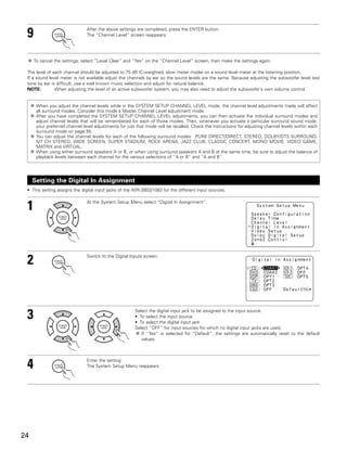
• “PHONO” and “TUNER” cannot be selected on the Digital In Assignment.
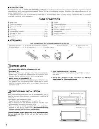
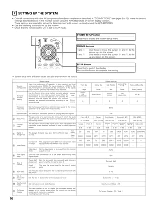
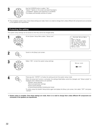
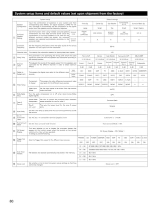
Setting the Video Setup
• This setting assigns the color difference (component) video input jacks of the AVR-3803/1083 for the different input sources.
[1] Setting the Component In Assign.
1 At the System Setup Menu select “Video Setup” and
press the ENTER button.
2 The “Video Setup” screen appears.
Select “Component In Assign.” and press the ENTER
button.
3 Switch to the Component In Assign. screen.
4 Select the component (Y, PB/CB and PR/CR) video input terminal to be assigned to the input source.
q Input source selection w Component video terminal selection
Select “NONE” for sources for which the component (Y, PB/CB and PR/CR) video input is not to be used.
When the default, “Yes”, is selected, the settings are reset to the factory defaults.
5 Press the ENTER button to complete the setting.
At the “Video Setup” screen, select “Exit” and press the ENTER button.
The System Setup Menu reappears.
25](https://image.slidesharecdn.com/700avr-3803en-091003022314-phpapp02/85/70-0-Avr-3803-En-25-320.jpg)
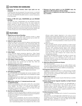
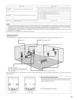
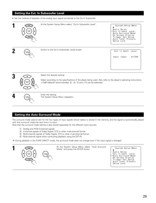
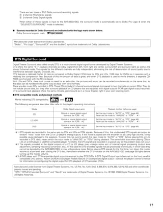
![[2] Setting the Video Input Mode
1 At the System Setup Menu select “Video Setup” and
press the ENTER button.
2 The “Video Setup” screen appears.
Select “Video Input Mode” and press the ENTER
button.
3 Switch the Video Input Mode screen.
4 q Select the input source for which you
want to set the Video Input Mode.
w Select the mode.
AUTO: When there are multiple input signals, the input signals are detected and the input signal to be output from the video
monitor output terminal is selected automatically in the following order: component video, S-Video, composite video.
Component: The signal connected to the component video terminal is always played.
Video conversion is not conducted, so no image is output from the monitor output terminal when there is no input signal
to the component terminal.
S-Video: The signal connected to the S-Video terminal is always played.
The S-Video input signal is converted and output from the composite and component monitor output terminal.
Video: The signal connected to the composite video terminal is always played.
The composite video input signal is up-converted and output from the S-Video and component monitor output terminals.
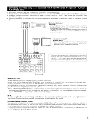
NOTE:
Down-converting from the component video signal to the S-Video and composite video signal is not possible, so when not using the
component video monitor output terminal connect the player using the S-Video or composite video input terminal.
Cautions on the video conversion function:
When the component video terminals are used to connect the AVR-3803/1083 with a TV (or monitor, projector, etc.) and the video (yellow)
or S video terminals are used to connect the AVR-3803/1083 with a VTR, depending on the combination of the TV and VTR the picture
may flicker in the horizontal direction, be distorted, be out of sync or not display at all when playing video tapes.
If this happens, connect a commercially available video stabilizer, etc., with a TBC (time base corrector) function between the AVR-
3803/1083 and the VTR, or if your VTR has a TBC function, turn it on.
5 Enter the setting.
At the “Video Setup” screen, select “Exit” and press the ENTER button.
The System Setup Menu reappears.
26](https://image.slidesharecdn.com/700avr-3803en-091003022314-phpapp02/85/70-0-Avr-3803-En-26-320.jpg)
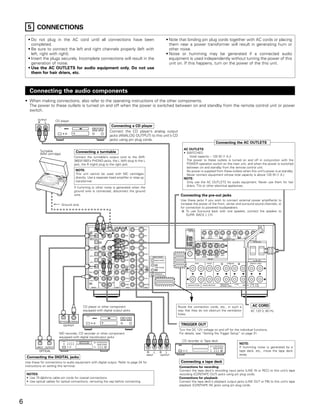
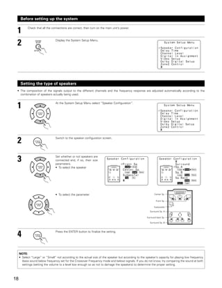
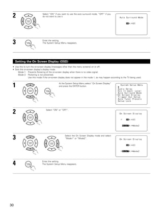
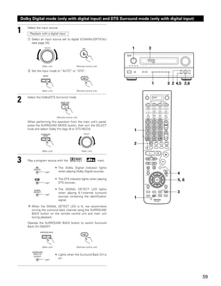
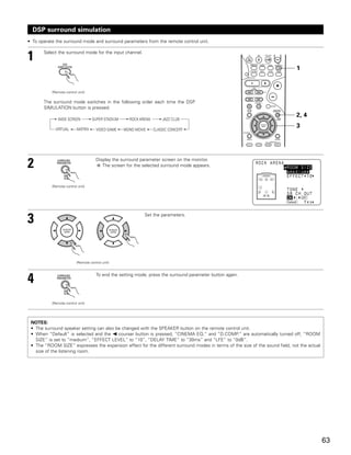
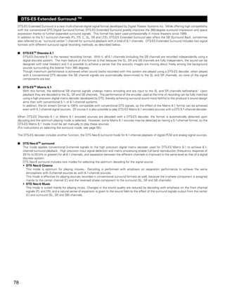
![Setting the Dolby Digital Setup
Sets the down-mixing method when not using a center speaker or surround speakers.
OFF: The dynamic range is not compressed.
ON: The dynamic range is compressed automatically according to the combination of speakers being used.
1 At the System Setup Menu select “Dolby Digital
Setup” and press the ENTER button.
2 Select “ON” if you want to use the Dolby Digital Down-mix, “OFF” if
you do not want to use it.
3 Enter the setting.
The System Setup Menu reappears.
Setting the ZONE2 Control
[1] Setting the power amplifier assignment
Make this setting to switch the power amplifier for the surround back channel to ZONE2.
If ZONE2 is selected, the signal that selected at ZONE2 is output at “SURR. BACK/ZONE2 PREOUT” terminals.
1 At the System Setup Menu select “Zone2 Control”
and press the ENTER button.
2 The “Zone2 Control” screen appears.
Select “Power Amp Assignment” and press the
ENTER button.
3 Select “Surround Back” to use as the surround back
channel, “Zone2” to use as Zone 2 out.
When “Surround Back” is selected When “Zone2” is selected
27](https://image.slidesharecdn.com/700avr-3803en-091003022314-phpapp02/85/70-0-Avr-3803-En-27-320.jpg)
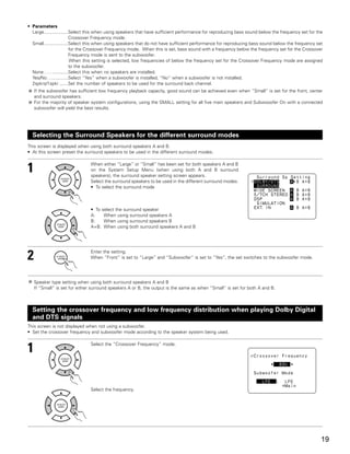
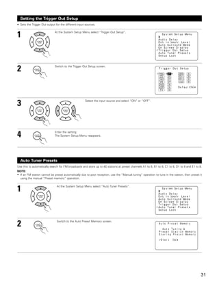
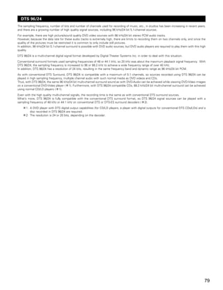
![4 Enter the setting.
At the “Zone2 Control” screen, select “Exit” and press the ENTER button.
The System Setup Menu reappears.
[2] Setting the Zone2 vol. level
Set the Zone 2 pre-out output level adjustment.
1 At the System Setup Menu select “Zone2 Control”
and press the ENTER button.
2 The “Zone2 Control” screen appears.
Select “Zone2 Vol. Level” and press the ENTER
button.
3 Select the desired settimg.
Variable:
The level can be adjusted freely using the buttons on the remote control
unit.
0 dB, -40 dB:
The output level is fixed at the set level and the volume can no longer be
adjusted.
4 Enter the setting.
At the “Zone2 Control” screen, select “Exit” and press the ENTER button.
The System Setup Menu reappears.
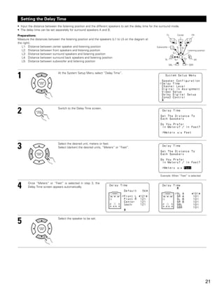
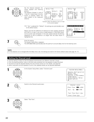
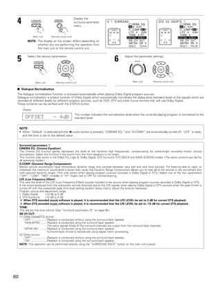
Setting the Audio Delay
This function allows you to adjust the time delay of the video and audio signals and store these settings for the different input sources.
The setting is made while watching a DVD or other software, so it is not made here.
By default, this is not displayed when no digital signals are being input.
For instructions on making the setting, refer to page 61.
NOTE:
The audio delay setting does not apply when playing in the EXT. IN mode or in the analog input direct mode or stereo mode (T0NE DEFEAT “ON”).
28](https://image.slidesharecdn.com/700avr-3803en-091003022314-phpapp02/85/70-0-Avr-3803-En-28-320.jpg)
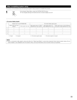
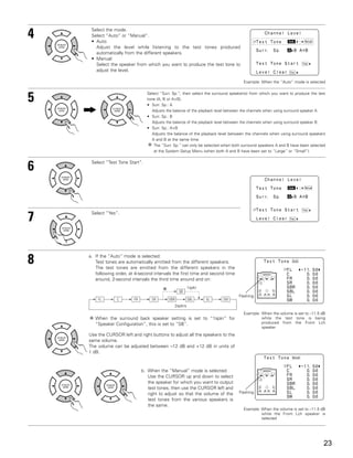
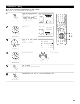
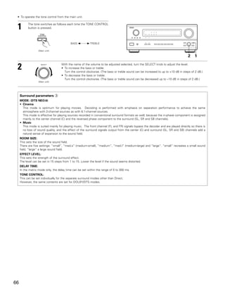
![After starting playback
[1] Adjusting the sound quality (TONE)
The tone control function will not work in the direct mode.
1 The tone switches as follows each time the TONE CONTROL
button is pressed.
BASS TREBLE
(Main unit)
2 31
2 With the name of the volume to be
adjusted selected, turn the SELECT
knob to adjust the level.
SELECT
(Main unit)
• To increase the bass or treble: Turn the control clockwise.
(The bass or treble sound can be increased to up to +10 dB
3 If you do not want the bass and treble to be adjusted, turn on
the tone defeat mode.
in steps of 2 dB.)
The signals do not pass through the
• To decrease the bass or treble: Turn the control clockwise.
bass and treble adjustment circuits,
(The bass or treble sound can be decreased to up to –10 dB
providing higher quality sound.
in steps of 2 dB.)
[2] Listening over headphones
1 Plug the headphones’ plug into
the jack.
Connect the headphones to
PHONES
the PHONES jack.
The pre-out output (including
the speaker output) is 1
automatically turned off when
headphones are connected.
1
NOTE:
To prevent hearing loss, do not raise the volume level excessively
when using headphones.
[3] Turning the sound off temporarily (MUTING)
1 Use this to turn off the audio output
temporarily.
Press the MUTING button. 1
Cancelling MUTING mode.
Press the MUTING button again.
(Remote control unit)
[4] Combining the currently playing sound with the desired image
1 Simulcast playback
Use this switch to monitor a
video source other than the
FUNCTION
1 1 1
audio source.
Press the VIDEO SELECT
button, turn the FUNCTION
knob until the desired (Main unit)
source appears on the
display.
Cancelling simulcast playback.
• Select “SOURCE” using the VIDEO SELECT button and
the FUNCTION button. Display
• Switch the program source to the component connected to
the video input. IN=V SOURCE
51](https://image.slidesharecdn.com/700avr-3803en-091003022314-phpapp02/85/70-0-Avr-3803-En-51-320.jpg)
![[5] Checking the currently playing program source, etc.
1 On screen display
• Each time an operation is performed,
a description of that operation
appears on the display connected to
the unit’s VIDEO MONITOR OUT 1
jack. Also, the unit’s operating status
can be checked during playback by
pressing the remote control unit’s ON
SCREEN/DISPLAY button.
Such information as the position of (Remote control unit)
the input selector and the surround
parameter settings is output in 1
sequence.
Front panel display Using the dimmer function
• Descriptions of the unit’s operations • Use this to change the brightness of the display.
are also displayed on the front panel The display brightness changes in four steps
display. In addition, the display can be (bright, medium, dim and off) by pressing the
switched to check the unit’s main unit’s DIMMER button repeatedly.
operating status while playing a (Main unit)
source by pressing the STATUS
button.
(Main unit)
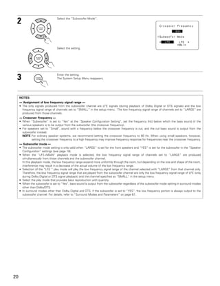
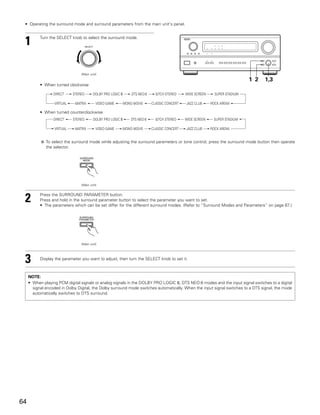
[6] Switching the surround speakers
1 The surround speakers switch as
shown below each time the SPEAKER
button is pressed.
SURROUND A SURROUND B
(Remote control unit)
1
SURROUND A+B
This operation is possible when the setting for using both
surround speakers A and B is made at “Speaker
Configuration” in the System Setup Menu.
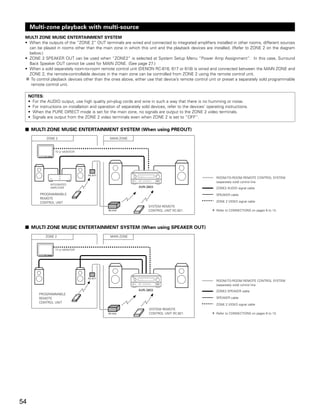
Multi-source recording/playback
[1] Playing one source while recording another (REC OUT mode)
1 Press the ZONE2/REC button.
2,4 2
(Main unit)
2 With “RECOUT SOURCE” displayed,
turn the FUNCTION knob to select the
source you wish to record.
FUNCTION
• The “REC” indicator and the
indicator of the selected source 1
light.
(Main unit)
Display 2
3 Set the recording mode.
• For operating instructions, refer to the manual of the
component on which you want to record.
REC PHONO CD TUNER
VCR -1 -2
DVD /
/
VDP TV / DBS
TAPE -1 -2
RECOUT SOURCE
4 To cancel, turn the function knob and select “SOURCE”.
• When “SOURCE” is selected, the “REC” indicator turns
off.
NOTES:
• Recording sources other than digital inputs selected in the REC
FUNCTION
OUT mode are also output to the Zone 2 preout jacks.
• Digital signals are not output from the REC SOURCE or audio
output jacks.
(Main unit)
52](https://image.slidesharecdn.com/700avr-3803en-091003022314-phpapp02/85/70-0-Avr-3803-En-52-320.jpg)
![[2] Outputting a program source to an amplifier, etc., in a different room (ZONE2 mode)
1 Press the ZONE2 button.
Light
3,5 3
(Main unit)
2 Press the ZONE2/REC button.
The display switches as follows each
time the button is pressed.
2 1
(Main unit) Display 2
3 With “ZONE2 SOURCE” displayed, turn PHONO CD TUNER DVD / VDP TV / DBS
FUNCTION MULTI VCR -1 -2 / TAPE -1 -2
the FUNCTION knob and select the
source you wish to output. ZONE2 SOURCE
• The indicator of the selected source
light.
NOTES:
(Main unit) • The signals of the source selected in the ZONE2 mode are also
output from the VCR-1, VCR-2 and CDR/TAPE recording output
jacks.
4 Start playing the source to be output.
• For operating instructions, refer to the manuals of the
respective components.
• Digital signals are not output from the ZONE2 audio output
jacks.
5 To cancel, turn the function knob and
select “SOURCE”.
FUNCTION
(Main unit)
[3] Remote control unit operations during multi-source playback (selecting the input source)
This operation is possible when ZONE2 mode is selected.
This operation is not possible in the REC OUT mode.
The main zone output can be
1 Select “ZONE2” using the AMP button. 2
1
turned on and off with the
“MAIN ON/OFF” button.
(Remote control unit)
2 Press the ZONE2 “ON” button.
To cancel the ZONE2 mode.
Press the ZONE2 “OFF” button.
3
(Remote control unit) 5
3 Press the input source button
• The ZONE2 source switches directly.
4 The output level of the ZONE 2 OUT
terminals can be controlled using the
VOLUME + and - buttons on the remote
4
control unit.
The output level of ZONE 2 OUT can be
controlled only if ZONE2 vol. level is set
“Variable” at Zone2 Control in System
Setup Menu. (See page 28)
(Remote control unit)
5 When the ZONE2 SOURCE function is
set to TUNER, the preset channel can
be selected using the CHANNEL + and
- buttons on the remote control unit.
DEFAULT SETTING (ZONE2 VOLUME LEVEL) :
- - - dB (MINIMUM)
(Remote control unit)
53](https://image.slidesharecdn.com/700avr-3803en-091003022314-phpapp02/85/70-0-Avr-3803-En-53-320.jpg)

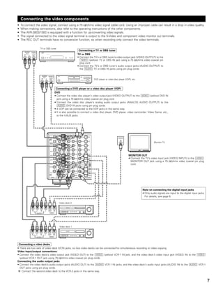
![17 SPECIFICATIONS
2 Audio section
• Power amplifier
Rated output: Front: 110 W + 110 W (8 Ω/ohms, 20 Hz ~ 20 kHz with 0.05% T.H.D.)
150 W + 150 W (6 Ω/ohms, 1 kHz with 0.7% T.H.D.)
Center: 110 W (8 Ω/ohms, 20 Hz ~ 20 kHz with 0.05% T.H.D.)
150 W (6 Ω/ohms, 1 kHz with 0.7% T.H.D.)
Surround: 110 W + 110 W (8 Ω/ohms, 20 Hz ~ 20 kHz with 0.05% T.H.D.)
150 W + 150 W (6 Ω/ohms, 1 kHz with 0.7% T.H.D.)
Surround Back: 110 W + 110 W (8 Ω/ohms, 20 Hz ~ 20 kHz with 0.05% T.H.D.)
150 W + 150 W (6 Ω/ohms, 1 kHz with 0.7% T.H.D.)
Dynamic power: 140 W x 2 ch (8 Ω/ohms)
210 W x 2 ch (4 Ω/ohms)
240 W x 2 ch (2 Ω/ohms)
Output terminals: Front, Center, Surr. Back/Zone 2: 6 ~ 16 Ω/ohms
Surround: A or B 6 ~ 16 Ω/ohms
A + B 8 ~ 16 Ω/ohms
• Analog
Input sensitivity / input impedance: 200 mV / 47 kΩ/kohms
Frequency response: 10 Hz ~ 100 kHz: +0, –3 dB (DIRECT mode)
S/N: 102 dB (DIRECT mode)
Distortion: 0.005% (20 Hz ~ 20 kHz) (DIRECT mode)
Rated output: 1.2 V
• Digital
D/A output: Rated output — 2 V (at 0 dB playback)
Total harmonic distortion — 0.008% (1 kHz, at 0 dB)
S/N ratio — 102 dB
Dynamic range — 96 dB
Digital input: Format — Digital audio interface
• Phono equalizer (PHONO input — REC OUT)
Input sensitivity: 2.5 mV
RIAA deviation: ±1 dB (20 Hz to 20 kHz)
Signal-to-noise ratio: 74 dB (A weighting, with 5 mV input)
Rated output / Maximum output: 150 mV / 8 V
Distortion factor: 0.03% (1 kHz, 3 V)
2 Video section
• Standard video jacks
Input / output level and impedance: 1 Vp-p, 75 Ω/ohms
Frequency response: 5 Hz ~ 10 MHz — +0, –3 dB
• S-video jacks
Input / output level and impedance: Y (brightness) signal — 1 Vp-p, 75 Ω/ohms
C (color) signal — 0.286 Vp-p, 75 Ω/ohms
Frequency response: 5 Hz ~ 10 MHz — +0, –3 dB
• Color component video jacks
Input / output level and impedance: Y (brightness) signal — 1 Vp-p, 75 Ω/ohms
PB/CB (blue) signal — 0.7 Vp-p, 75 Ω/ohms
PR/CR (red) signal — 0.7Vp-p, 75 Ω/ohms
Frequency response: DC ~ 100 MHz — +0, –3 dB
2 Tuner section
[FM] (note: µV at 75 Ω/ohms, 0 dBf=1 x 10–15 W) [AM]
Receiving Range: 87.50 MHz ~ 107.90 MHz 520 kHz ~ 1710 kHz
Usable Sensitivity: 1.0 µV (11.2 dBf) 18 µV
50 dB Quieting Sensitivity: MONO 1.6 µV (15.3 dBf)
STEREO 23 µV (38.5 dBf)
S/N (IHF-A): MONO 77 dB
STEREO 72 dB
Total Harmonic Distortion (at 1 kHz): MONO 0.15%
STEREO 0.3%
2 General
Power supply: AC 120 V, 60 Hz
Power consumption: 7.0 A
1 W Max (Standby)
Maximum external dimensions: 434 (W) x 171 (H) x 416 (D) mm (17-3/32” x 6-47/64” x 16-3/8”)
Mass: 16.5 kg (36 lbs 6 oz)
2 Remote control unit (RC-921)
Batteries: R6P/AA Type (three batteries)
External dimensions: 58 (W) x 230 (H) x 37 (D) mm (2-9/32” x 9-1/16” x 1-29/64”)
Mass: 230 g (Approx. 8 oz) (including batteries)
* For purposes of improvement, specifications and design are subject to change without notice.
83](https://image.slidesharecdn.com/700avr-3803en-091003022314-phpapp02/85/70-0-Avr-3803-En-83-320.jpg)