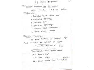
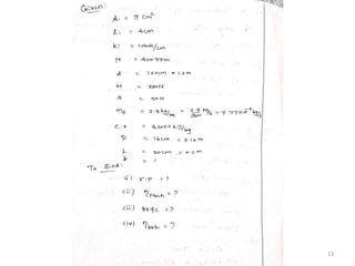
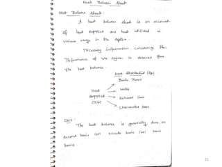
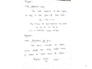
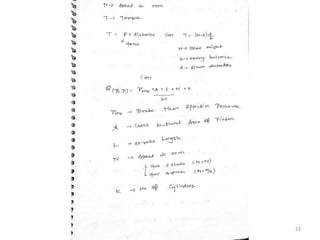
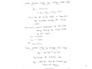
IC ENGINES
P. Marimuthu, M.E
Teaching Fellow
CEG, Anna University
Terminology used in IC engine
Terminology used in IC engine:
1. Cylinder bore (D):
The nominal inner diameter of the working cylinder.
2. Piston area (A):
The area of circle of diameter equal to the cylinder bore.
3. Stroke (L):
The nominal distance through which a working piston moves between two successive
reversals of its direction of motion.
2
Terminology used in IC engine
4. Dead centre:
The position of the working piston and the moving parts which are mechanically
connected to it at the moment when the direction of the piston motion is reversed (at either end
point of the stroke).
(a) Bottom dead centre (BDC): Dead centre when the piston is nearest to the
crankshaft.
(b) Top dead centre (TDC): Dead centre when the position is farthest from the
crankshaft.
5. Displacement volume or swept volume (Vs):
The nominal volume generated by the working piston when travelling from the one
dead Centre to next one and given as,
Vs=A × L
3
Terminology used in IC engine
6. Clearance volume (Vc):
The nominal volume of the space on the combustion side of the piston at the top
dead centre.
7. Cylinder volume (V):
Total volume of the cylinder.
V= Vs + Vc
8. Compression ratio (r):
It is defined as the volume of before compression to the volume of after
compression.
r =
𝑉1
𝑉2
4
Basic Automobile Engineering 5
Basic Automobile Engineering 6
Basic Automobile Engineering 7
Basic Automobile Engineering 8
Basic Automobile Engineering 9
Basic Automobile Engineering 10
Basic Automobile Engineering 11
Basic Automobile Engineering 12
Basic Automobile Engineering 13
Basic Automobile Engineering 14
Basic Automobile Engineering 15
Basic Automobile Engineering 16
Basic Automobile Engineering 17
Basic Automobile Engineering 18
Basic Automobile Engineering 19
Basic Automobile Engineering 20
Basic Automobile Engineering 21
Basic Automobile Engineering 22
Basic Automobile Engineering 23
Basic Automobile Engineering 24
Basic Automobile Engineering 25
Basic Automobile Engineering 26
Basic Automobile Engineering 27
28
Basic Automobile Engineering 29
Basic Automobile Engineering 30
Basic Automobile Engineering 31
Basic Automobile Engineering 32
Basic Automobile Engineering 33
Basic Automobile Engineering 34
35
Basic Automobile Engineering 36
Basic Automobile Engineering 37
Basic Automobile Engineering 38
Basic Automobile Engineering 39
8/29/2022 Basic Automobile Engineering 40
41
Morse Test
The friction force power of an engine is determined by the following methods :
(a) Willan's line method.
(b) Morse test.
(c) Motoring test.
42
Morse Test
Morse Test
• The Morse test is applicable only to multicylinder engines.
• In this test, the engine is first run at the required speed and the output is measured.
• Then, one cylinder is cut out by short circuiting the spark plug or by disconnecting
the injector as the case may be. Under this condition all other cylinders motor this
cut-out cylinder.
• The output is measured by keeping the speed constant at its original value. The
difference in the outputs is a measure of the indicated horse power of the cut-out
cylinder.
43
Morse Test
• Thus, for each cylinder the ip is obtained and is added together to find the total ip of
the engine.
• This method though gives reasonably accurate results and is liable to errors due to
changes in mixture distribution and other conditions by cutting-out one cylinder. In
gasoline engines, where there is a common manifold for two or more cylinders the
mixture distribution as well as the volumetric efficiency both change.
• Again, almost all engines have a common exhaust manifold for all cylinders and
cutting out of one cylinder may greatly affect the pulsations in exhaust system
which may significantly change the engine performance by imposing different back
pressures.
44
Basic Automobile Engineering 45
Basic Automobile Engineering 46
47
48
49
50
51
52
53
54
55
Basic Automobile Engineering 56
Two types of fuel injection system
Throttle body injection system (single point) :
• It consists of a single injector for the entire engine. It is mounted above the throttle
volve. It supplies air fuel mixture just like carburetor system. Its initial cost is less.
Port injection system (multi point):
• In this system is a separate injector for each cylinder mounted in the inlet port.
• The injectors inject fuel onto the back of the inlet valves (indirect method).
• Injectors may spray directly into the cylinder (direct method).
57
Injector
• The injectors use a needle and seat
type valve to control the fuel flow.
• The fuel pressure is fed to both top
and bottom of the needle valve.
• The pressure at the bottom will push
the needle off its seat by bleeding
some of the pressure of the top.
• Thus the fuel will flow through
nozzle holes.
58
59
Multi Point Fuel Injection (MPFI)
MPFI :
• The purpose of this system is to supply proper A/F mixture to each cylinder of the
engine.
• The entire system is controlled by ECU (Electronic control unit) by getting data
from vital locations through sensors, processing the data with inbuilt data and gives
signals to the (actuators) injectors which determines the time and quantity of fuel
injections.
Types :
• Throttle injection
• Port injection
60
Throttle injection
• This system single injector is used
like a single carburetor. The throttle
valve controls the amount of air
entering in the intake manifold.
• The injector is located above the
throat of the body and injected fuel
mixes with air, then the mixture
passes into the intake manifold. The
fuel injected is controlled as per the
speed and load on the engine.
61
Port injection
• The injector is fitted in the inlet
manifold near the inlet valve. The
uniform mixture formed enters
into the cylinder.
• Every cylinder is provided with a
separate injector in multi cylinder
engine.
62
63
64
Injection types
65
Common Rail Injection System
A Common Rail system consists of pressure
accumulator called Common Rail which is
mounted on the engine block.
The rail is fed by a high pressure pump (1800 to
2200bar)
The injectors are activated by solenoid valves.
Both solenoid valve and fuel pump are controlled
by ECU.
In this system the injection pressure is not depend
on engine speed and load.
66
Common Rail Injection System
67
Advantages of CRDI
Advantages:
• System is simple and less maintenance cost. Only one pump is sufficient for
multi cylinder engine.
• Pilot injection is possible and thereby reduce engine noise and Nitrogen
emissions.
• It gives superior pick up and higher mileage. The fuel consumption is less.
• It fulfills requirements of either constant load with variable speeds or variable
loads with constant speed
68
IGNITION SYSTEMS
• Ignition system is a part of electrical systems which carries the electrical current to
the spark plug.
• To start the ignition in the combustion chamber it is necessary to rise the
temperature of the mixture to its ignition temperature where the chemical reaction
starts.
• The energy required for this purpose is supplied by an electrical spark.
• The system supplies high voltage of current (as much as 20000 V) to produce spark
in spark plug.
• This system provides spark at the exact time in various cylinders according to the
firing order.
69
TYPES OF IGNITION SYSTEMS
Types of ignition systems :
(a) Battery or Coil Ignition System, and
(b) Magneto Ignition System.
(c) Electronic Ignition System is as follow :
(i) Capacitance Discharge Ignition system
(ii) Transistorized system
(iii) Piezo-electric Ignition system
(iv) The Texaco Ignition system
70
Battery or Coil Ignition System
71
Battery or Coil Ignition System
When the contact breaker points closed :
• The circuit is closed when the ignition switch is put ON.
• The current builds up a magnetic field in the primary winding of the ignition coil.
• When the primary current is at the highest peak, the contact breaker points will be opened by the
cam.
When the contact breaker points closed :
• The magnetic field sets up in the primary winding is suddenly collapsed.
• A high voltage (15000 V) is generated in the secondary winding of the ignition coil.
• This high voltage is directed to the rotor of the distributor.
• The rotor directs this voltage to the individual spark plugs according to the firing order.
• The high voltage tries to cross the spark plug gap (0.45 to 0.6 mm) and the spark is produced.
• This spark ignites the air fuel mixture.
72
Battery or Coil Ignition System
Advantages :
• It provides better spark even at low speed of the engine.
• The initial cost is low as compared with magneto ignition system.
• The maintenance cost is negligible except the battery.
• The spark intensity is not affected by timing control mechanism.
Disadvantages :
• Heavier than magneto ignition system.
• If the battery is weak the engine can not be started.
• The breaker points are continuously subjected to wear.
• The sparking voltage drops as the speed increases.
73
Magneto Ignition System
74
Magneto Ignition System
Construction :
• This system consists of a rotating magnet assembly driven by engine and a fixed
armature.
• This armature consists of primary and secondary windings.
• The primary circuit consists of a primary winding, condenser and contact breaker.
• The secondary circuit consist of secondary winding, distributor and spark plugs.
75
Magneto Ignition System
Working :
When the contact breaker points are closed :
• Current flows in the primary and it produces in the magnetic field in the primary circuit.
• When the primary current is at the highest peak the contact breaker ponts will be opened by
the cam.
When the contact breaker points are opened :
• The primary circuit breaks the magnetic field in the primary winding is suddenly collapsed.
• A high voltage (as much as 15000 V) is generated in the secondary winding.
• This high voltage is distributed to plugs according to firing order by this distributor.
• The high voltage at the spark plug creates spark, while crossing the electrodes, to ignite the
charge in the cylinder.
76
Magneto Ignition System
Advantages :
• It is more reliable and low maintenance because absence of battery.
• It requires less space and the weight also less compare to battery ignition system.
• At higher speeds it gives high intensity of spark and thus it can give better
combustion at higher speeds.
Disadvantages :
• The initial cost is very high compare to battery ignition system.
• It requires minimum 75 rpm to start the engine.
• For bigger engines some other device is necessary to start the engine.
77
Difference between Battery and Magneto Ignition System
8/29/2022 Basic Automobile Engineering 78
ELECTRONIC (capacitance discharge) IGNITION SYSTEM
• It mainly consists of 6-12 V battery, ignition
switch, DC to DC convertor, charging
resistance, tank capacitor, Silicon Controlled
Rectifier (SCR), SCR-triggering device, step
up transformer, spark plugs.
• A 6-12 volt battery is connected to DC to DC
converter i.e. power circuit through the ignition
switch, which is designed to give or increase
the voltage to 250-350 volts.
• This high voltage is used to charge the tank
capacitor (or condenser) to this voltage through
the charging resistance.
79
ELECTRONIC (capacitance discharge) IGNITION SYSTEM
The charging resistance is also so designed that it
controls the required current in the SCR.
Depending upon the engine firing order, whenever
the SCR triggering device, sends a pulse, then the
current flowing through the primary winding is
stopped.
And the magnetic field begins to collapse. This
collapsing magnetic field will induce or step up
high voltage current in the secondary, which while
jumping the spark plug gap produces the spark,
and the charge of air fuel mixture is ignited.
80
Purpose of Lubrication system
The lubrication system has several functions:
• Absorb shock loading from compression, power stroke, engine braking, etc.
• Increase fuel economy by providing low friction surfaces.
• Cleaning the internal components of dirt and other particles.
• Remove heat from engine components.
• Reduce friction between engine components.
81
Lubrication system
82
Types of Lubrication system
Types of Lubrication system:
various lubrication system used for IC engines are,
(a) Mist lubrication system
(b) Wet sump lubrication system
(i) Splash system
(ii) Splash and pressure system
(iii) Pressure feed system
(c) Dry sump lubrication system
83
Mist Lubrication
Mist Lubrication :
• Certain amount of lubricating oil is
mixed with petrol itself, the usual
ratio is 2% to 3%.
• When the petrol mixture enters into
the crankcase due to high temperature
, the petrol vapourized leaving a thin
film of lubricating oil on the crank
case, cylinder walls, crank shaft and
bearings.
84
Splash system
(i) Splash system :
• In this system of lubrication the lubricating
oil is stored in an oil sump. A scoop or dipper
is made in the lower part of the connecting
rod.
• When the engine runs, the dipper dips in the
oil once in every revolution of the crank
shaft, the oil is splashed on the cylinder wall.
Due to this action engine walls, piston ring,
crank shaft bearings are lubricated.
• It is used for light duty engine
85
Pressure feed system
Pressure feed system:
• In this system of lubrication, the engine parts
are lubricated under pressure feed. The
lubricating oil is stored in a separate tank (in
case of dry sump system) or in the sump (in
case of wet sump system), from where an oil
pump (gear pump) delivers the oil to the main
oil gallery at a pressure of 2-4 kg/cm2
through an oil filter.
• The oil from the main gallery goes to main
bearing, from where some of it falls back to
the sump after lubricating the main bearing
and some is splashed to lubricate the cylinder
walls and remaining goes through a hole to
the crank pin.
86
Pressure feed system
• From the crank pin the lubricating oil goes
to the piston pin through a hole in the
connecting rod, where it lubricates the
piston rings. For lubricating cam shaft and
gears the oil is led through a separate oil
line from the oil gallery. The oil pressure
gauge used in the system indicates the oil
pressure in the system. Oil filter & strainer
in the system clear off the oil from dust,
metal particles and other harmful particles.
87
88
Splash and pressure system
Splash and pressure system:
• Lubricating oil is supplied under
pressure to main, camshaft
bearings and pipes which direct a
stream of oil against the dippers
on the big end of connecting rod
bearing cup and thus crankpin
bearings are lubricated by the
splash or spray of oil thrown up
by the dipper.
89
Dry sump Lubrication system
(c) Dry sump lubrication system:
• Supply of oil is carried in external tank.
Oil pump draws oil from the supply tank
and circulates it under pressure to various
bearings of the engine.
• Oil dripping from the cylinders and
bearings into the sump is removed by a
scavenging pump and again return to
supply tank through the filter.
• The capacity of scavenging pump is
greater than the oil pump. Separate oil
cooler to remove heat from oil is used
which is either cooled by air or water.
90
91
Cooling System
• Combustion of air and fuel takes place inside the engine cylinder hot gases are
generated.
• The temperature of gases will be around 2300 to 2500℃.
• Too much cooling is also not desirable since it reduces the thermal efficiency.
92
Types of cooling system
Types of cooling system:
Air Cooling or direct cooling system :
(a) Natural cooling
(b) Forced cooling
Water Cooling or Indirect cooling system :
(a) Thermo-syphon cooling
(b) Forced or pump cooling
(c) Cooling with thermostatic regulator
(d) Pressurized water cooling system
(e) Evaporative cooling
93
Air cooling system
• The method of cooling an engine by the use of atmospheric air is called Air cooling.
• The heat from inside the cylinder is spread over a large area of the outer surface of
the cylinder head and cylinder by providing fan as shown here under.
94
Air cooling system
• The amount of heat dissipated to
depends upon :
– Amount of air flowing through
the fins
– Fin surface area
– Thermal conductivity of metal
used for fins.
95
Advantages and Disadvantages
Advantages :
• Light in wait since there are no radiator, cooling water and pipe lines.
• No coolant used and hence no leakage and no anti-freeze requirement.
• Warming up is faster.
• Maintenance is easy and hence it is cheaper.
• Manufacturing cost is less.
Disadvantages :
• It is less efficient since air is a poor conductor of heat compared to water.
• Uniform cooling is not possible in all climate conditions.
• Producers more noise.
• It is suitable for small engines only.
96
Liquid cooling system
• A water pump is installed to improve water circulation, which is driven by a V belt
from a pulley on the crankshaft.
• When the hot water in engine passes through the radiator tubes from vapor tank to
lower tank, it is exposed to a large amount of airflow due to fan rotation and
sufficiently gets cooled.
• Then it is pumped to cylinder jackets by the water pump.
• The automatic thermostat valve is used to regulate the circulation of water so that
very cold water will become hot in short time to improve efficiency of the engine.
97
Pump circulation system
Major Parts :
• Radiator
• Thermostat valve
• Upper & Lower radiator
hoses
• Radiator cap
• Water pump
• Water pump belt
• By pass pipe
• Fan
98
Advantages and Disadvantages
Advantages :
• Uniform cooling of cylinder, cylinder head and valves.
• Specific fuel consumption of engine improves by using water cooling system.
• Engine is less noisy is compared with air cooled engines, as it has water for
damping noise.
Disadvantages :
• The water pump which circulates water absorbs considerable power.
• The water cooling system is consider as it has more number of parts.
99
Supercharger
100
Supercharger
• Supercharger, in piston-type internal-combustion engines, air compressor or
blower used to increase the intake manifold pressure of the engine. Higher pressure
increases the mass of air drawn into the cylinders by the pumping action of the
pistons during each intake stroke. With the additional air, it is possible to burn more
fuel per cycle, and the power of the engine is thus increased.
• In aircraft piston engines, supercharging compensates for the reduced atmospheric
pressure at high altitudes. Development of the gas turbine, which requires constant
flow of air and fuel, brought the introduction of the turbosupercharger, or simply
turbocharger, a centrifugal blower driven by a small gas turbine powered by the
exhaust gases from the engine cylinders.
101
Turbocharger
102
Turbocharger
• A turbocharger or turbo is a forced induction device used to allow more power to be
produced for an engine of a given size.
• A turbocharged engine can be more powerful and efficient than a naturally aspirated
engine because the turbine forces more air, and proportionately more fuel, into the
combustion chamber than atmospheric pressure alone.
103
Turbocharger
Working principle
• A turbocharger is a small radial fan pump driven by the energy of the exhaust gases of an engine. A
turbocharger consists of a turbine and a compressor on a shared shaft.
• The turbine section of a turbocharger is a heat engine in itself. It converts the heat energy from the
exhaust to power, which then drives the compressor, compressing ambient air and delivering it to the
air intake manifold of the engine at higher pressure, resulting in a greater mass of air entering each
• cylinder.
• In some instances, compressed air is routed through an intercooler before introduction to the intake
manifold.
• Because a turbocharger is a heat engine, and is converting otherwise wasted exhaust heat to power, it
compresses the inlet air to the engine more efficiently than a supercharger.
104
Combined Supercharger and Turbocharger
105
8/29/2022 Basic Automobile Engineering 106
Emission characteristics of Engines
Principal Engine Emissions
SI Engines : CO, HC and NOx
CI Engines : CO, HC, NOx and PM
Emission Norms for 2/3 Wheelers ( Petrol)
Norms CO ( g/km) HC+ NOx (g/km)
1991 norms 12-30 8-12 (only HC)
1996 norms 4.5 3.6
stage
2000 norms
2.0 2.0
Bharat stage-II 1.6 1.5
Bharat Stage-III 1.0 1.0
Emission norms for Heavy diesel vehicles:
Norms CO
(g/kwhr)
HC
(g/kwhr)
Nox
(g/kwhr)
PM
(g/kwhr)
1991 Norms 14 3.5 18 -
1996 Norms 11.2 2.4 14.4 -
stage 2000 Norms 4.5 1.1 8.0 0.36
Bharat stage-II 4.0 1.1 7.0 0.15
Bharat Stage-III 2.1 1.6 5.0 0.10
Bharat Stage-IV 1.5 0.96 3.5 0.02
Hydrocarbon Emission Sources for SI Engines
There are six primary Sources believed to be responsible for
hydrocarbon emissions:
% fuel escaping
Source normal combustion % HC emissions
Crevices 5.2 38
Oil layers 1.0 16
Deposits 1.0 16
Liquid fuel 1.2 20
Flame quench 0.5 5
Exhaust valve leakage 0.1 5
Total 9.0 100
Formation of CO in IC Engines
• Formation of CO is well established.
• Locally, there may not be enough O2 available for complete
oxidation and some of the carbon in the fuel ends up as CO.
• Even at sufficient oxygen level, high peak temperatures can cause
dissociation.
• Conversion of CO to CO2 is governed by reaction
H
CO
OH
CO 

 2
• Dissociated CO may freeze during the expansion stroke.
Particulates
• A high concentration of particulate matter (PM) is manifested as
visible smoke in the exhaust gases.
• Particulates are any substance other than water that can be
collected by filtering the exhaust, classified as: Solid carbon
material or soot, Condensed hydrocarbons and their partial
oxidation products.
• Diesel particulates consist of solid carbon (soot) at exhaust gas
temperatures below 500oC, HC compounds become absorbed
on the surface.
• In a properly adjusted SI engines soot is not usually a problem .
• Particulate can arise if leaded fuel or overly rich fuel-air mixture
are used.
• Burning crankcase oil will also produce smoke especially during
engine warm up where the HC condense in the exhaust gas.
EGR Systems
• Exhaust gas recirculation (EGR) is a nitrogen oxide (NOx) emissions
reduction technique used in petrol/gasoline and diesel engines.
• NOx is produced in high temperature mixtures of atmospheric
nitrogen and oxygen that occur in the combustion cylinder, and this
usually occurs at cylinder peak pressure.
• EGR works by recirculating a portion of an engine's exhaust gas
back to the engine cylinders.
• This dilutes the Oxygen in the incoming air stream and provides
gases to act as absorbents of combustion heat to reduce peak in-
cylinder temperatures.
• Another primary benefit of external EGR valves on a spark ignition
engine is an increase in efficiency, as charge dilution allows a larger
throttle position and reduces associated pumping loss
• In a gasoline engine, this inert exhaust displaces some amount of
combustible charge in the cylinder, effectively reducing the quantity
of charge available for combustion without affecting the air-fuel
ratios.
8/29/2022 Basic Automobile Engineering 112
Continued…
• In a typical automotive S.I engine, 5% to 15% of the exhaust gas is
routed back to the intake as EGR.
• The maximum quantity is limited by the need of the mixture to
sustain a continuous flame front during the combustion event;
excessive EGR in poorly set up applications can cause misfires and
partial burns.
• Although EGR does measurably slow combustion, this can largely
be compensated for by advancing spark timing.
• The impact of EGR on engine efficiency largely depends on the
specific engine design, and sometimes leads to a compromise
between efficiency and NOx emissions.
• Reduced throttling losses. The addition of inert exhaust gas into
the intake system means that for a given power output, the throttle
plate must be opened further, resulting in increased inlet manifold
pressure and reduced throttling losses.
• Reduced heat rejection. Lowered peak combustion temperatures
not only reduces NOx formation, it also reduces the loss of thermal
energy to combustion chamber surfaces, leaving more available for
conversion to mechanical work during the expansion stroke.
8/29/2022 Basic Automobile Engineering 113
8/29/2022 Basic Automobile Engineering 114
Continued………..
• The engine computer (PCM) opens or closes
the EGR valve to control the flow within the
EGR system.
• The EGR valve connects the exhaust manifold
to the intake manifold.
• The EGR valve is normally closed. There is no
EGR flow when the engine is cold, at idle, or
during hard acceleration.
• The EGR flow is at its peak during steady
cruising under moderate load.
8/29/2022 Basic Automobile Engineering 115
CATALYTIC CONVERTER
• A catalytic converter is an exhaust emission control device that reduces
toxic gases and pollutants in exhaust gas from an internal combustion
engine into less-toxic pollutants by catalyzing a redox reaction (an
oxidation and a reduction reaction). Catalytic converters are usually used
with internal combustion engines fueled by either gasoline or diesel.
• The "two-way" converters combine oxygen with carbon monoxide (CO)
and unburned hydrocarbons to produce carbon dioxide (CO2) and water
(H2O). In “"three-way" converters that also reduce oxides of nitrogen
(NOx).
• However, two-way converters are still used for lean-burn engines. This is
because three-way-converters require either rich or stoichiometric
combustion to successfully reduce NOx.
• The three catalytic materials are known as Platinum Group Materials
(PGM). These includes Platinum (Pt),Palladium (Pd) and Rhodium (Rh).
• The substrate can be made up of Metal or Ceramic (e.g. Silicon Carbide
(SiC), Zirconia (ZrO2) etc.). The substrate is coated with the platinum,
palladium and rhodium materials.
8/29/2022 Basic Automobile Engineering 116
8/29/2022 Basic Automobile Engineering 117
8/29/2022 Basic Automobile Engineering 118
• These three reactions occur most efficiently when the catalytic converter
receives exhaust from an engine running slightly above the stoichiometric
point. For gasoline combustion, this ratio is between 14.6 and 14.8 parts air to
one part fuel, by weight.
• Under lean engine operation, the exhaust contains excess oxygen, and the
reduction of NOx is not favored.
• Under rich conditions, the excess fuel consumes all of the available oxygen
prior to the catalyst, leaving only oxygen stored in the catalyst available for the
oxidation function.
Continued……
• Unwanted reactions can occur in the three-way
catalyst, such as the formation of odoriferous hydrogen
sulfide and ammonia.
• It is difficult to eliminate these byproducts entirely.
Sulfur-free or low-sulfur fuels eliminate or reduce
hydrogen sulfide.
• For compression-ignition (i.e., diesel) engines, the most
commonly used catalytic converter is the Diesel
oxidation catalyst (DOC).
• DOCs contain palladium, platinum, and aluminium
oxide, all of which catalytically oxidize the particulate
matter (PM), hydrocarbons, and carbon monoxide with
oxygen to form carbon dioxide and water.
8/29/2022 Basic Automobile Engineering 119
DIESEL PARTICULATE FILTER (DPF)
• A diesel particulate filter (DPF) is a device designed to remove
diesel particulate matter or soot from the exhaust gas of a diesel
engine.
• Diesel particulate matter resulting from the incomplete
combustion of diesel fuel produces soot (black carbon) particles.
• These particles include tiny nanoparticles—smaller than one
micrometer (one micron). Soot and other particles from diesel
engines worsen the particulate matter pollution in the air and
are harmful to health.
• The quality of the fuel also influences the formation of these
particles. For example, a high sulphur content diesel produces
more particles. Lower sulphur fuel produces fewer particles, and
allows use of particulate filters. The injection pressure of diesel
also influences the formation of fine particles.
8/29/2022 Basic Automobile Engineering 120
Continued…..
• Wall-flow diesel particulate filters usually remove 85% or
more of the soot, and under certain conditions can attain
soot removal efficiencies approaching 100%.
• Some filters are single-use, intended for disposal and
replacement once full of accumulated ash.
• Others are designed to burn off the accumulated
particulate either passively through the use of a catalyst or
by active means such as a fuel burner.
• This is accomplished by engine programming to run (when
the filter is full) in a manner that elevates exhaust
temperature, in conjunction with an extra fuel injector in
the exhaust stream that injects fuel to react with a catalyst
element to burn off accumulated soot in the DPF filter.
8/29/2022 Basic Automobile Engineering 121
UNIT III
TRANSMISSION SYSTEMS
8/29/2022 Basic Automobile Engineering 122
8/29/2022 Basic Automobile Engineering 123

UNIT-V-IC Engine Performance.pptx

  • 1.
    IC ENGINES P. Marimuthu,M.E Teaching Fellow CEG, Anna University
  • 2.
    Terminology used inIC engine Terminology used in IC engine: 1. Cylinder bore (D): The nominal inner diameter of the working cylinder. 2. Piston area (A): The area of circle of diameter equal to the cylinder bore. 3. Stroke (L): The nominal distance through which a working piston moves between two successive reversals of its direction of motion. 2
  • 3.
    Terminology used inIC engine 4. Dead centre: The position of the working piston and the moving parts which are mechanically connected to it at the moment when the direction of the piston motion is reversed (at either end point of the stroke). (a) Bottom dead centre (BDC): Dead centre when the piston is nearest to the crankshaft. (b) Top dead centre (TDC): Dead centre when the position is farthest from the crankshaft. 5. Displacement volume or swept volume (Vs): The nominal volume generated by the working piston when travelling from the one dead Centre to next one and given as, Vs=A × L 3
  • 4.
    Terminology used inIC engine 6. Clearance volume (Vc): The nominal volume of the space on the combustion side of the piston at the top dead centre. 7. Cylinder volume (V): Total volume of the cylinder. V= Vs + Vc 8. Compression ratio (r): It is defined as the volume of before compression to the volume of after compression. r = 𝑉1 𝑉2 4
  • 5.
  • 6.
  • 7.
  • 8.
  • 9.
  • 10.
  • 11.
  • 12.
  • 13.
  • 14.
  • 15.
  • 16.
  • 17.
  • 18.
  • 19.
  • 20.
  • 21.
  • 22.
  • 23.
  • 24.
  • 25.
  • 26.
  • 27.
  • 28.
  • 29.
  • 30.
  • 31.
  • 32.
  • 33.
  • 34.
  • 35.
  • 36.
  • 37.
  • 38.
  • 39.
  • 40.
  • 41.
  • 42.
    Morse Test The frictionforce power of an engine is determined by the following methods : (a) Willan's line method. (b) Morse test. (c) Motoring test. 42
  • 43.
    Morse Test Morse Test •The Morse test is applicable only to multicylinder engines. • In this test, the engine is first run at the required speed and the output is measured. • Then, one cylinder is cut out by short circuiting the spark plug or by disconnecting the injector as the case may be. Under this condition all other cylinders motor this cut-out cylinder. • The output is measured by keeping the speed constant at its original value. The difference in the outputs is a measure of the indicated horse power of the cut-out cylinder. 43
  • 44.
    Morse Test • Thus,for each cylinder the ip is obtained and is added together to find the total ip of the engine. • This method though gives reasonably accurate results and is liable to errors due to changes in mixture distribution and other conditions by cutting-out one cylinder. In gasoline engines, where there is a common manifold for two or more cylinders the mixture distribution as well as the volumetric efficiency both change. • Again, almost all engines have a common exhaust manifold for all cylinders and cutting out of one cylinder may greatly affect the pulsations in exhaust system which may significantly change the engine performance by imposing different back pressures. 44
  • 45.
  • 46.
  • 47.
  • 48.
  • 49.
  • 50.
  • 51.
  • 52.
  • 53.
  • 54.
  • 55.
  • 56.
  • 57.
    Two types offuel injection system Throttle body injection system (single point) : • It consists of a single injector for the entire engine. It is mounted above the throttle volve. It supplies air fuel mixture just like carburetor system. Its initial cost is less. Port injection system (multi point): • In this system is a separate injector for each cylinder mounted in the inlet port. • The injectors inject fuel onto the back of the inlet valves (indirect method). • Injectors may spray directly into the cylinder (direct method). 57
  • 58.
    Injector • The injectorsuse a needle and seat type valve to control the fuel flow. • The fuel pressure is fed to both top and bottom of the needle valve. • The pressure at the bottom will push the needle off its seat by bleeding some of the pressure of the top. • Thus the fuel will flow through nozzle holes. 58
  • 59.
  • 60.
    Multi Point FuelInjection (MPFI) MPFI : • The purpose of this system is to supply proper A/F mixture to each cylinder of the engine. • The entire system is controlled by ECU (Electronic control unit) by getting data from vital locations through sensors, processing the data with inbuilt data and gives signals to the (actuators) injectors which determines the time and quantity of fuel injections. Types : • Throttle injection • Port injection 60
  • 61.
    Throttle injection • Thissystem single injector is used like a single carburetor. The throttle valve controls the amount of air entering in the intake manifold. • The injector is located above the throat of the body and injected fuel mixes with air, then the mixture passes into the intake manifold. The fuel injected is controlled as per the speed and load on the engine. 61
  • 62.
    Port injection • Theinjector is fitted in the inlet manifold near the inlet valve. The uniform mixture formed enters into the cylinder. • Every cylinder is provided with a separate injector in multi cylinder engine. 62
  • 63.
  • 64.
  • 65.
  • 66.
    Common Rail InjectionSystem A Common Rail system consists of pressure accumulator called Common Rail which is mounted on the engine block. The rail is fed by a high pressure pump (1800 to 2200bar) The injectors are activated by solenoid valves. Both solenoid valve and fuel pump are controlled by ECU. In this system the injection pressure is not depend on engine speed and load. 66
  • 67.
  • 68.
    Advantages of CRDI Advantages: •System is simple and less maintenance cost. Only one pump is sufficient for multi cylinder engine. • Pilot injection is possible and thereby reduce engine noise and Nitrogen emissions. • It gives superior pick up and higher mileage. The fuel consumption is less. • It fulfills requirements of either constant load with variable speeds or variable loads with constant speed 68
  • 69.
    IGNITION SYSTEMS • Ignitionsystem is a part of electrical systems which carries the electrical current to the spark plug. • To start the ignition in the combustion chamber it is necessary to rise the temperature of the mixture to its ignition temperature where the chemical reaction starts. • The energy required for this purpose is supplied by an electrical spark. • The system supplies high voltage of current (as much as 20000 V) to produce spark in spark plug. • This system provides spark at the exact time in various cylinders according to the firing order. 69
  • 70.
    TYPES OF IGNITIONSYSTEMS Types of ignition systems : (a) Battery or Coil Ignition System, and (b) Magneto Ignition System. (c) Electronic Ignition System is as follow : (i) Capacitance Discharge Ignition system (ii) Transistorized system (iii) Piezo-electric Ignition system (iv) The Texaco Ignition system 70
  • 71.
    Battery or CoilIgnition System 71
  • 72.
    Battery or CoilIgnition System When the contact breaker points closed : • The circuit is closed when the ignition switch is put ON. • The current builds up a magnetic field in the primary winding of the ignition coil. • When the primary current is at the highest peak, the contact breaker points will be opened by the cam. When the contact breaker points closed : • The magnetic field sets up in the primary winding is suddenly collapsed. • A high voltage (15000 V) is generated in the secondary winding of the ignition coil. • This high voltage is directed to the rotor of the distributor. • The rotor directs this voltage to the individual spark plugs according to the firing order. • The high voltage tries to cross the spark plug gap (0.45 to 0.6 mm) and the spark is produced. • This spark ignites the air fuel mixture. 72
  • 73.
    Battery or CoilIgnition System Advantages : • It provides better spark even at low speed of the engine. • The initial cost is low as compared with magneto ignition system. • The maintenance cost is negligible except the battery. • The spark intensity is not affected by timing control mechanism. Disadvantages : • Heavier than magneto ignition system. • If the battery is weak the engine can not be started. • The breaker points are continuously subjected to wear. • The sparking voltage drops as the speed increases. 73
  • 74.
  • 75.
    Magneto Ignition System Construction: • This system consists of a rotating magnet assembly driven by engine and a fixed armature. • This armature consists of primary and secondary windings. • The primary circuit consists of a primary winding, condenser and contact breaker. • The secondary circuit consist of secondary winding, distributor and spark plugs. 75
  • 76.
    Magneto Ignition System Working: When the contact breaker points are closed : • Current flows in the primary and it produces in the magnetic field in the primary circuit. • When the primary current is at the highest peak the contact breaker ponts will be opened by the cam. When the contact breaker points are opened : • The primary circuit breaks the magnetic field in the primary winding is suddenly collapsed. • A high voltage (as much as 15000 V) is generated in the secondary winding. • This high voltage is distributed to plugs according to firing order by this distributor. • The high voltage at the spark plug creates spark, while crossing the electrodes, to ignite the charge in the cylinder. 76
  • 77.
    Magneto Ignition System Advantages: • It is more reliable and low maintenance because absence of battery. • It requires less space and the weight also less compare to battery ignition system. • At higher speeds it gives high intensity of spark and thus it can give better combustion at higher speeds. Disadvantages : • The initial cost is very high compare to battery ignition system. • It requires minimum 75 rpm to start the engine. • For bigger engines some other device is necessary to start the engine. 77
  • 78.
    Difference between Batteryand Magneto Ignition System 8/29/2022 Basic Automobile Engineering 78
  • 79.
    ELECTRONIC (capacitance discharge)IGNITION SYSTEM • It mainly consists of 6-12 V battery, ignition switch, DC to DC convertor, charging resistance, tank capacitor, Silicon Controlled Rectifier (SCR), SCR-triggering device, step up transformer, spark plugs. • A 6-12 volt battery is connected to DC to DC converter i.e. power circuit through the ignition switch, which is designed to give or increase the voltage to 250-350 volts. • This high voltage is used to charge the tank capacitor (or condenser) to this voltage through the charging resistance. 79
  • 80.
    ELECTRONIC (capacitance discharge)IGNITION SYSTEM The charging resistance is also so designed that it controls the required current in the SCR. Depending upon the engine firing order, whenever the SCR triggering device, sends a pulse, then the current flowing through the primary winding is stopped. And the magnetic field begins to collapse. This collapsing magnetic field will induce or step up high voltage current in the secondary, which while jumping the spark plug gap produces the spark, and the charge of air fuel mixture is ignited. 80
  • 81.
    Purpose of Lubricationsystem The lubrication system has several functions: • Absorb shock loading from compression, power stroke, engine braking, etc. • Increase fuel economy by providing low friction surfaces. • Cleaning the internal components of dirt and other particles. • Remove heat from engine components. • Reduce friction between engine components. 81
  • 82.
  • 83.
    Types of Lubricationsystem Types of Lubrication system: various lubrication system used for IC engines are, (a) Mist lubrication system (b) Wet sump lubrication system (i) Splash system (ii) Splash and pressure system (iii) Pressure feed system (c) Dry sump lubrication system 83
  • 84.
    Mist Lubrication Mist Lubrication: • Certain amount of lubricating oil is mixed with petrol itself, the usual ratio is 2% to 3%. • When the petrol mixture enters into the crankcase due to high temperature , the petrol vapourized leaving a thin film of lubricating oil on the crank case, cylinder walls, crank shaft and bearings. 84
  • 85.
    Splash system (i) Splashsystem : • In this system of lubrication the lubricating oil is stored in an oil sump. A scoop or dipper is made in the lower part of the connecting rod. • When the engine runs, the dipper dips in the oil once in every revolution of the crank shaft, the oil is splashed on the cylinder wall. Due to this action engine walls, piston ring, crank shaft bearings are lubricated. • It is used for light duty engine 85
  • 86.
    Pressure feed system Pressurefeed system: • In this system of lubrication, the engine parts are lubricated under pressure feed. The lubricating oil is stored in a separate tank (in case of dry sump system) or in the sump (in case of wet sump system), from where an oil pump (gear pump) delivers the oil to the main oil gallery at a pressure of 2-4 kg/cm2 through an oil filter. • The oil from the main gallery goes to main bearing, from where some of it falls back to the sump after lubricating the main bearing and some is splashed to lubricate the cylinder walls and remaining goes through a hole to the crank pin. 86
  • 87.
    Pressure feed system •From the crank pin the lubricating oil goes to the piston pin through a hole in the connecting rod, where it lubricates the piston rings. For lubricating cam shaft and gears the oil is led through a separate oil line from the oil gallery. The oil pressure gauge used in the system indicates the oil pressure in the system. Oil filter & strainer in the system clear off the oil from dust, metal particles and other harmful particles. 87
  • 88.
  • 89.
    Splash and pressuresystem Splash and pressure system: • Lubricating oil is supplied under pressure to main, camshaft bearings and pipes which direct a stream of oil against the dippers on the big end of connecting rod bearing cup and thus crankpin bearings are lubricated by the splash or spray of oil thrown up by the dipper. 89
  • 90.
    Dry sump Lubricationsystem (c) Dry sump lubrication system: • Supply of oil is carried in external tank. Oil pump draws oil from the supply tank and circulates it under pressure to various bearings of the engine. • Oil dripping from the cylinders and bearings into the sump is removed by a scavenging pump and again return to supply tank through the filter. • The capacity of scavenging pump is greater than the oil pump. Separate oil cooler to remove heat from oil is used which is either cooled by air or water. 90
  • 91.
  • 92.
    Cooling System • Combustionof air and fuel takes place inside the engine cylinder hot gases are generated. • The temperature of gases will be around 2300 to 2500℃. • Too much cooling is also not desirable since it reduces the thermal efficiency. 92
  • 93.
    Types of coolingsystem Types of cooling system: Air Cooling or direct cooling system : (a) Natural cooling (b) Forced cooling Water Cooling or Indirect cooling system : (a) Thermo-syphon cooling (b) Forced or pump cooling (c) Cooling with thermostatic regulator (d) Pressurized water cooling system (e) Evaporative cooling 93
  • 94.
    Air cooling system •The method of cooling an engine by the use of atmospheric air is called Air cooling. • The heat from inside the cylinder is spread over a large area of the outer surface of the cylinder head and cylinder by providing fan as shown here under. 94
  • 95.
    Air cooling system •The amount of heat dissipated to depends upon : – Amount of air flowing through the fins – Fin surface area – Thermal conductivity of metal used for fins. 95
  • 96.
    Advantages and Disadvantages Advantages: • Light in wait since there are no radiator, cooling water and pipe lines. • No coolant used and hence no leakage and no anti-freeze requirement. • Warming up is faster. • Maintenance is easy and hence it is cheaper. • Manufacturing cost is less. Disadvantages : • It is less efficient since air is a poor conductor of heat compared to water. • Uniform cooling is not possible in all climate conditions. • Producers more noise. • It is suitable for small engines only. 96
  • 97.
    Liquid cooling system •A water pump is installed to improve water circulation, which is driven by a V belt from a pulley on the crankshaft. • When the hot water in engine passes through the radiator tubes from vapor tank to lower tank, it is exposed to a large amount of airflow due to fan rotation and sufficiently gets cooled. • Then it is pumped to cylinder jackets by the water pump. • The automatic thermostat valve is used to regulate the circulation of water so that very cold water will become hot in short time to improve efficiency of the engine. 97
  • 98.
    Pump circulation system MajorParts : • Radiator • Thermostat valve • Upper & Lower radiator hoses • Radiator cap • Water pump • Water pump belt • By pass pipe • Fan 98
  • 99.
    Advantages and Disadvantages Advantages: • Uniform cooling of cylinder, cylinder head and valves. • Specific fuel consumption of engine improves by using water cooling system. • Engine is less noisy is compared with air cooled engines, as it has water for damping noise. Disadvantages : • The water pump which circulates water absorbs considerable power. • The water cooling system is consider as it has more number of parts. 99
  • 100.
  • 101.
    Supercharger • Supercharger, inpiston-type internal-combustion engines, air compressor or blower used to increase the intake manifold pressure of the engine. Higher pressure increases the mass of air drawn into the cylinders by the pumping action of the pistons during each intake stroke. With the additional air, it is possible to burn more fuel per cycle, and the power of the engine is thus increased. • In aircraft piston engines, supercharging compensates for the reduced atmospheric pressure at high altitudes. Development of the gas turbine, which requires constant flow of air and fuel, brought the introduction of the turbosupercharger, or simply turbocharger, a centrifugal blower driven by a small gas turbine powered by the exhaust gases from the engine cylinders. 101
  • 102.
  • 103.
    Turbocharger • A turbochargeror turbo is a forced induction device used to allow more power to be produced for an engine of a given size. • A turbocharged engine can be more powerful and efficient than a naturally aspirated engine because the turbine forces more air, and proportionately more fuel, into the combustion chamber than atmospheric pressure alone. 103
  • 104.
    Turbocharger Working principle • Aturbocharger is a small radial fan pump driven by the energy of the exhaust gases of an engine. A turbocharger consists of a turbine and a compressor on a shared shaft. • The turbine section of a turbocharger is a heat engine in itself. It converts the heat energy from the exhaust to power, which then drives the compressor, compressing ambient air and delivering it to the air intake manifold of the engine at higher pressure, resulting in a greater mass of air entering each • cylinder. • In some instances, compressed air is routed through an intercooler before introduction to the intake manifold. • Because a turbocharger is a heat engine, and is converting otherwise wasted exhaust heat to power, it compresses the inlet air to the engine more efficiently than a supercharger. 104
  • 105.
    Combined Supercharger andTurbocharger 105
  • 106.
    8/29/2022 Basic AutomobileEngineering 106 Emission characteristics of Engines Principal Engine Emissions SI Engines : CO, HC and NOx CI Engines : CO, HC, NOx and PM
  • 107.
    Emission Norms for2/3 Wheelers ( Petrol) Norms CO ( g/km) HC+ NOx (g/km) 1991 norms 12-30 8-12 (only HC) 1996 norms 4.5 3.6 stage 2000 norms 2.0 2.0 Bharat stage-II 1.6 1.5 Bharat Stage-III 1.0 1.0
  • 108.
    Emission norms forHeavy diesel vehicles: Norms CO (g/kwhr) HC (g/kwhr) Nox (g/kwhr) PM (g/kwhr) 1991 Norms 14 3.5 18 - 1996 Norms 11.2 2.4 14.4 - stage 2000 Norms 4.5 1.1 8.0 0.36 Bharat stage-II 4.0 1.1 7.0 0.15 Bharat Stage-III 2.1 1.6 5.0 0.10 Bharat Stage-IV 1.5 0.96 3.5 0.02
  • 109.
    Hydrocarbon Emission Sourcesfor SI Engines There are six primary Sources believed to be responsible for hydrocarbon emissions: % fuel escaping Source normal combustion % HC emissions Crevices 5.2 38 Oil layers 1.0 16 Deposits 1.0 16 Liquid fuel 1.2 20 Flame quench 0.5 5 Exhaust valve leakage 0.1 5 Total 9.0 100
  • 110.
    Formation of COin IC Engines • Formation of CO is well established. • Locally, there may not be enough O2 available for complete oxidation and some of the carbon in the fuel ends up as CO. • Even at sufficient oxygen level, high peak temperatures can cause dissociation. • Conversion of CO to CO2 is governed by reaction H CO OH CO    2 • Dissociated CO may freeze during the expansion stroke.
  • 111.
    Particulates • A highconcentration of particulate matter (PM) is manifested as visible smoke in the exhaust gases. • Particulates are any substance other than water that can be collected by filtering the exhaust, classified as: Solid carbon material or soot, Condensed hydrocarbons and their partial oxidation products. • Diesel particulates consist of solid carbon (soot) at exhaust gas temperatures below 500oC, HC compounds become absorbed on the surface. • In a properly adjusted SI engines soot is not usually a problem . • Particulate can arise if leaded fuel or overly rich fuel-air mixture are used. • Burning crankcase oil will also produce smoke especially during engine warm up where the HC condense in the exhaust gas.
  • 112.
    EGR Systems • Exhaustgas recirculation (EGR) is a nitrogen oxide (NOx) emissions reduction technique used in petrol/gasoline and diesel engines. • NOx is produced in high temperature mixtures of atmospheric nitrogen and oxygen that occur in the combustion cylinder, and this usually occurs at cylinder peak pressure. • EGR works by recirculating a portion of an engine's exhaust gas back to the engine cylinders. • This dilutes the Oxygen in the incoming air stream and provides gases to act as absorbents of combustion heat to reduce peak in- cylinder temperatures. • Another primary benefit of external EGR valves on a spark ignition engine is an increase in efficiency, as charge dilution allows a larger throttle position and reduces associated pumping loss • In a gasoline engine, this inert exhaust displaces some amount of combustible charge in the cylinder, effectively reducing the quantity of charge available for combustion without affecting the air-fuel ratios. 8/29/2022 Basic Automobile Engineering 112
  • 113.
    Continued… • In atypical automotive S.I engine, 5% to 15% of the exhaust gas is routed back to the intake as EGR. • The maximum quantity is limited by the need of the mixture to sustain a continuous flame front during the combustion event; excessive EGR in poorly set up applications can cause misfires and partial burns. • Although EGR does measurably slow combustion, this can largely be compensated for by advancing spark timing. • The impact of EGR on engine efficiency largely depends on the specific engine design, and sometimes leads to a compromise between efficiency and NOx emissions. • Reduced throttling losses. The addition of inert exhaust gas into the intake system means that for a given power output, the throttle plate must be opened further, resulting in increased inlet manifold pressure and reduced throttling losses. • Reduced heat rejection. Lowered peak combustion temperatures not only reduces NOx formation, it also reduces the loss of thermal energy to combustion chamber surfaces, leaving more available for conversion to mechanical work during the expansion stroke. 8/29/2022 Basic Automobile Engineering 113
  • 114.
  • 115.
    Continued……….. • The enginecomputer (PCM) opens or closes the EGR valve to control the flow within the EGR system. • The EGR valve connects the exhaust manifold to the intake manifold. • The EGR valve is normally closed. There is no EGR flow when the engine is cold, at idle, or during hard acceleration. • The EGR flow is at its peak during steady cruising under moderate load. 8/29/2022 Basic Automobile Engineering 115
  • 116.
    CATALYTIC CONVERTER • Acatalytic converter is an exhaust emission control device that reduces toxic gases and pollutants in exhaust gas from an internal combustion engine into less-toxic pollutants by catalyzing a redox reaction (an oxidation and a reduction reaction). Catalytic converters are usually used with internal combustion engines fueled by either gasoline or diesel. • The "two-way" converters combine oxygen with carbon monoxide (CO) and unburned hydrocarbons to produce carbon dioxide (CO2) and water (H2O). In “"three-way" converters that also reduce oxides of nitrogen (NOx). • However, two-way converters are still used for lean-burn engines. This is because three-way-converters require either rich or stoichiometric combustion to successfully reduce NOx. • The three catalytic materials are known as Platinum Group Materials (PGM). These includes Platinum (Pt),Palladium (Pd) and Rhodium (Rh). • The substrate can be made up of Metal or Ceramic (e.g. Silicon Carbide (SiC), Zirconia (ZrO2) etc.). The substrate is coated with the platinum, palladium and rhodium materials. 8/29/2022 Basic Automobile Engineering 116
  • 117.
  • 118.
    8/29/2022 Basic AutomobileEngineering 118 • These three reactions occur most efficiently when the catalytic converter receives exhaust from an engine running slightly above the stoichiometric point. For gasoline combustion, this ratio is between 14.6 and 14.8 parts air to one part fuel, by weight. • Under lean engine operation, the exhaust contains excess oxygen, and the reduction of NOx is not favored. • Under rich conditions, the excess fuel consumes all of the available oxygen prior to the catalyst, leaving only oxygen stored in the catalyst available for the oxidation function.
  • 119.
    Continued…… • Unwanted reactionscan occur in the three-way catalyst, such as the formation of odoriferous hydrogen sulfide and ammonia. • It is difficult to eliminate these byproducts entirely. Sulfur-free or low-sulfur fuels eliminate or reduce hydrogen sulfide. • For compression-ignition (i.e., diesel) engines, the most commonly used catalytic converter is the Diesel oxidation catalyst (DOC). • DOCs contain palladium, platinum, and aluminium oxide, all of which catalytically oxidize the particulate matter (PM), hydrocarbons, and carbon monoxide with oxygen to form carbon dioxide and water. 8/29/2022 Basic Automobile Engineering 119
  • 120.
    DIESEL PARTICULATE FILTER(DPF) • A diesel particulate filter (DPF) is a device designed to remove diesel particulate matter or soot from the exhaust gas of a diesel engine. • Diesel particulate matter resulting from the incomplete combustion of diesel fuel produces soot (black carbon) particles. • These particles include tiny nanoparticles—smaller than one micrometer (one micron). Soot and other particles from diesel engines worsen the particulate matter pollution in the air and are harmful to health. • The quality of the fuel also influences the formation of these particles. For example, a high sulphur content diesel produces more particles. Lower sulphur fuel produces fewer particles, and allows use of particulate filters. The injection pressure of diesel also influences the formation of fine particles. 8/29/2022 Basic Automobile Engineering 120
  • 121.
    Continued….. • Wall-flow dieselparticulate filters usually remove 85% or more of the soot, and under certain conditions can attain soot removal efficiencies approaching 100%. • Some filters are single-use, intended for disposal and replacement once full of accumulated ash. • Others are designed to burn off the accumulated particulate either passively through the use of a catalyst or by active means such as a fuel burner. • This is accomplished by engine programming to run (when the filter is full) in a manner that elevates exhaust temperature, in conjunction with an extra fuel injector in the exhaust stream that injects fuel to react with a catalyst element to burn off accumulated soot in the DPF filter. 8/29/2022 Basic Automobile Engineering 121
  • 122.
    UNIT III TRANSMISSION SYSTEMS 8/29/2022Basic Automobile Engineering 122
  • 123.