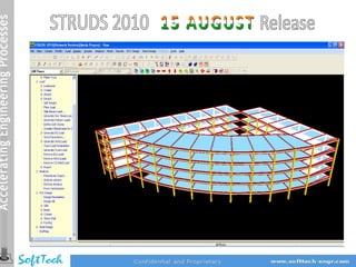
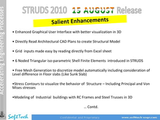
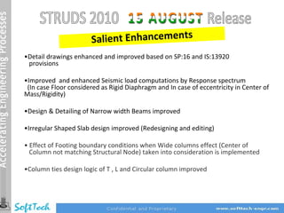
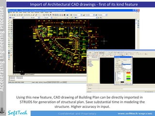
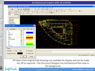
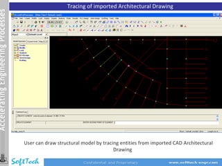
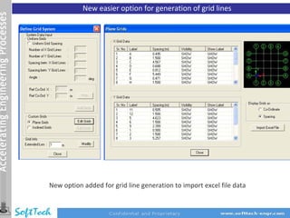
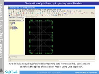
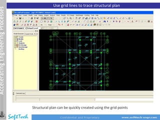
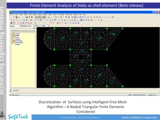
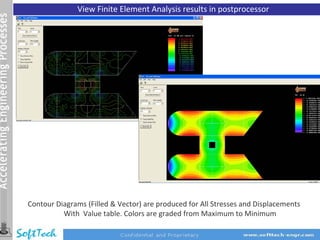
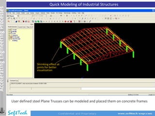
Salient Enhancements
• Enhanced Graphical User Interface with better visualization in 3D

• Directly Read Architectural CAD Plans to create Structural Model

• Grid inputs made easy by reading directly from Excel sheet

• 6 Noded Triangular iso‐parametric Shell Finite Elements introduced in STRUDS

• Free Mesh Generation to discretize model automatically including consideration of
Level difference in Floor slabs (Like Sunk Slab)

•Stress Contours to visualize the behavior of Structure – Including Principal and Von
Mises stresses

•Modeling of Industrial buildings with RC Frames and Steel Trusses in 3D

                                            … Contd.
Salient Enhancements
•Detail drawings enhanced and improved based on SP:16 and IS:13920
 provisions

•Improved and enhanced Seismic load computations by Response spectrum
 (In case Floor considered as Rigid Diaphragm and In case of eccentricity in Center of
Mass/Rigidity)

•Design & Detailing of Narrow width Beams improved

•Irregular Shaped Slab design improved (Redesigning and editing)

• Effect of Footing boundary conditions when Wide columns effect (Center of
  Column not matching Structural Node) taken into consideration is implemented

•Column ties design logic of T , L and Circular column improved
Import of Architectural CAD drawings ‐ first of its kind feature


Using this new feature, CAD drawing of Building Plan can be directly imported in
  STRUDS for generation of structural plan. Save substantial time in modeling the
                         structure. Higher accuracy in input.
Architectural import with all entities


All layers from original CAD drawings are available for display and can be made
     on/ off as required – The Structural Designer has Architectural Plan view in
                                   the background
Tracing of imported Architectural Drawing


User can draw structural model by tracing entities from imported CAD Architectural
                                       Drawing
New easier option for generation of grid lines


New option added for grid line generation to import excel file data
Generation of grid lines by importing excel file data


Grid lines can now be generated by importing data from excel file. Substantially
            enhances the speed of creation of model using Grid approach.
Use grid lines to trace structural plan


Structural plan can be quickly created using the grid points
Finite Element Analysis of Slabs as shell element (Beta release)


    Discretization of Surfaces using Intelligent Free Mesh
         Algorithm – 6 Noded Triangular Finite Elements
                           Considered
View Finite Element Analysis results in postprocessor


Contour Diagrams (Filled & Vector) are produced for All Stresses and Displacements
          With Value table. Colors are graded from Maximum to Minimum
Quick Modeling of Industrial Structures


               Shrinking effect at
               joints for better
               visualization


User defined steel Plane Trusses can be modeled and placed them on concrete frames
Minor Improvements / Fixation of Bugs


Preprocessor
• Enhanced accuracy in report for contribution of columns in EQ resistance

Design
• Matching of reports for analysis and design loads for shear walls subjected to
   earthquake and wind loads.
• Effect of boundary conditions as hinged / fixed at footing level while considering the
   option ‘Consider stiffness at the center of column’, in the ‘column offset’ command.
• Deflection control check for Steel Grade Fe550 improved in design of slabs.
Minor Improvements / Fixation of Bugs


Detailing
• Proper directions of arrows indicating section lines for generation of beam cross
   section drawings.
• Display of dimensions in millimeters in DXF drawings for slabs, beams, columns and
   footings for better graphics judgment.
• Hooks at both ends for top bars and bottom curtailed bars in L/s of beams have been
   added as per generally accepted detailing practice.
• Enhanced and more accurate curtailment for bottom steel in beams.
•   New provision to provide curtailment positions from support (values for ‘C’ and ‘D’)
    under 'Beam Detailing Parameter' dialogue box in beam design.
•   Generation of Beam L/s DXF drawings considering effect of orientation of columns.
•   User defined control parameters for curtailment of top extra bars as per SP‐16
•   Text annotation of Beam numbers improved in print option of Beam Plan layout

                                  END OF RELEASE NOTES

14 struds 2010 (Aug release)

  • 2.
    Salient Enhancements • EnhancedGraphical User Interface with better visualization in 3D • Directly Read Architectural CAD Plans to create Structural Model • Grid inputs made easy by reading directly from Excel sheet • 6 Noded Triangular iso‐parametric Shell Finite Elements introduced in STRUDS • Free Mesh Generation to discretize model automatically including consideration of Level difference in Floor slabs (Like Sunk Slab) •Stress Contours to visualize the behavior of Structure – Including Principal and Von Mises stresses •Modeling of Industrial buildings with RC Frames and Steel Trusses in 3D … Contd.
  • 3.
    Salient Enhancements •Detail drawingsenhanced and improved based on SP:16 and IS:13920 provisions •Improved and enhanced Seismic load computations by Response spectrum (In case Floor considered as Rigid Diaphragm and In case of eccentricity in Center of Mass/Rigidity) •Design & Detailing of Narrow width Beams improved •Irregular Shaped Slab design improved (Redesigning and editing) • Effect of Footing boundary conditions when Wide columns effect (Center of Column not matching Structural Node) taken into consideration is implemented •Column ties design logic of T , L and Circular column improved
  • 4.
    Import of ArchitecturalCAD drawings ‐ first of its kind feature Using this new feature, CAD drawing of Building Plan can be directly imported in STRUDS for generation of structural plan. Save substantial time in modeling the structure. Higher accuracy in input.
  • 5.
    Architectural import withall entities All layers from original CAD drawings are available for display and can be made on/ off as required – The Structural Designer has Architectural Plan view in the background
  • 6.
    Tracing of importedArchitectural Drawing User can draw structural model by tracing entities from imported CAD Architectural Drawing
  • 7.
    New easier optionfor generation of grid lines New option added for grid line generation to import excel file data
  • 8.
    Generation of gridlines by importing excel file data Grid lines can now be generated by importing data from excel file. Substantially enhances the speed of creation of model using Grid approach.
  • 9.
    Use grid linesto trace structural plan Structural plan can be quickly created using the grid points
  • 10.
    Finite Element Analysisof Slabs as shell element (Beta release) Discretization of Surfaces using Intelligent Free Mesh Algorithm – 6 Noded Triangular Finite Elements Considered
  • 11.
    View Finite ElementAnalysis results in postprocessor Contour Diagrams (Filled & Vector) are produced for All Stresses and Displacements With Value table. Colors are graded from Maximum to Minimum
  • 12.
    Quick Modeling ofIndustrial Structures Shrinking effect at joints for better visualization User defined steel Plane Trusses can be modeled and placed them on concrete frames
  • 13.
    Minor Improvements /Fixation of Bugs Preprocessor • Enhanced accuracy in report for contribution of columns in EQ resistance Design • Matching of reports for analysis and design loads for shear walls subjected to earthquake and wind loads. • Effect of boundary conditions as hinged / fixed at footing level while considering the option ‘Consider stiffness at the center of column’, in the ‘column offset’ command. • Deflection control check for Steel Grade Fe550 improved in design of slabs.
  • 14.
    Minor Improvements /Fixation of Bugs Detailing • Proper directions of arrows indicating section lines for generation of beam cross section drawings. • Display of dimensions in millimeters in DXF drawings for slabs, beams, columns and footings for better graphics judgment. • Hooks at both ends for top bars and bottom curtailed bars in L/s of beams have been added as per generally accepted detailing practice. • Enhanced and more accurate curtailment for bottom steel in beams. • New provision to provide curtailment positions from support (values for ‘C’ and ‘D’) under 'Beam Detailing Parameter' dialogue box in beam design. • Generation of Beam L/s DXF drawings considering effect of orientation of columns. • User defined control parameters for curtailment of top extra bars as per SP‐16 • Text annotation of Beam numbers improved in print option of Beam Plan layout END OF RELEASE NOTES