Dev Dives: Train smarter, not harder – active learning and UiPath LLMs for do...UiPathCommunity
💥 Speed, accuracy, and scaling – discover the superpowers of GenAI in action with UiPath Document Understanding and Communications Mining™:
See how to accelerate model training and optimize model performance with active learning
Learn about the latest enhancements to out-of-the-box document processing – with little to no training required
Get an exclusive demo of the new family of UiPath LLMs – GenAI models specialized for processing different types of documents and messages
This is a hands-on session specifically designed for automation developers and AI enthusiasts seeking to enhance their knowledge in leveraging the latest intelligent document processing capabilities offered by UiPath.
Speakers:
👨🏫 Andras Palfi, Senior Product Manager, UiPath
👩🏫 Lenka Dulovicova, Product Program Manager, UiPath
Kubernetes & AI - Beauty and the Beast !?! @KCD Istanbul 2024Tobias Schneck
As AI technology is pushing into IT I was wondering myself, as an “infrastructure container kubernetes guy”, how get this fancy AI technology get managed from an infrastructure operational view? Is it possible to apply our lovely cloud native principals as well? What benefit’s both technologies could bring to each other?
Let me take this questions and provide you a short journey through existing deployment models and use cases for AI software. On practical examples, we discuss what cloud/on-premise strategy we may need for applying it to our own infrastructure to get it to work from an enterprise perspective. I want to give an overview about infrastructure requirements and technologies, what could be beneficial or limiting your AI use cases in an enterprise environment. An interactive Demo will give you some insides, what approaches I got already working for real.
DevOps and Testing slides at DASA ConnectKari Kakkonen
My and Rik Marselis slides at 30.5.2024 DASA Connect conference. We discuss about what is testing, then what is agile testing and finally what is Testing in DevOps. Finally we had lovely workshop with the participants trying to find out different ways to think about quality and testing in different parts of the DevOps infinity loop.
Key Trends Shaping the Future of Infrastructure.pdfCheryl Hung
Keynote at DIGIT West Expo, Glasgow on 29 May 2024.
Cheryl Hung, ochery.com
Sr Director, Infrastructure Ecosystem, Arm.
The key trends across hardware, cloud and open-source; exploring how these areas are likely to mature and develop over the short and long-term, and then considering how organisations can position themselves to adapt and thrive.
JMeter webinar - integration with InfluxDB and GrafanaRTTS
Watch this recorded webinar about real-time monitoring of application performance. See how to integrate Apache JMeter, the open-source leader in performance testing, with InfluxDB, the open-source time-series database, and Grafana, the open-source analytics and visualization application.
In this webinar, we will review the benefits of leveraging InfluxDB and Grafana when executing load tests and demonstrate how these tools are used to visualize performance metrics.
Length: 30 minutes
Session Overview
-------------------------------------------
During this webinar, we will cover the following topics while demonstrating the integrations of JMeter, InfluxDB and Grafana:
- What out-of-the-box solutions are available for real-time monitoring JMeter tests?
- What are the benefits of integrating InfluxDB and Grafana into the load testing stack?
- Which features are provided by Grafana?
- Demonstration of InfluxDB and Grafana using a practice web application
To view the webinar recording, go to:
https://www.rttsweb.com/jmeter-integration-webinar
Smart TV Buyer Insights Survey 2024 by 91mobiles.pdf91mobiles
91mobiles recently conducted a Smart TV Buyer Insights Survey in which we asked over 3,000 respondents about the TV they own, aspects they look at on a new TV, and their TV buying preferences.
Accelerate your Kubernetes clusters with Varnish CachingThijs Feryn
A presentation about the usage and availability of Varnish on Kubernetes. This talk explores the capabilities of Varnish caching and shows how to use the Varnish Helm chart to deploy it to Kubernetes.
This presentation was delivered at K8SUG Singapore. See https://feryn.eu/presentations/accelerate-your-kubernetes-clusters-with-varnish-caching-k8sug-singapore-28-2024 for more details.
UiPath Test Automation using UiPath Test Suite series, part 3DianaGray10
Welcome to UiPath Test Automation using UiPath Test Suite series part 3. In this session, we will cover desktop automation along with UI automation.
Topics covered:
UI automation Introduction,
UI automation Sample
Desktop automation flow
Pradeep Chinnala, Senior Consultant Automation Developer @WonderBotz and UiPath MVP
Deepak Rai, Automation Practice Lead, Boundaryless Group and UiPath MVP
Essentials of Automations: Optimizing FME Workflows with ParametersSafe Software
Are you looking to streamline your workflows and boost your projects’ efficiency? Do you find yourself searching for ways to add flexibility and control over your FME workflows? If so, you’re in the right place.
Join us for an insightful dive into the world of FME parameters, a critical element in optimizing workflow efficiency. This webinar marks the beginning of our three-part “Essentials of Automation” series. This first webinar is designed to equip you with the knowledge and skills to utilize parameters effectively: enhancing the flexibility, maintainability, and user control of your FME projects.
Here’s what you’ll gain:
- Essentials of FME Parameters: Understand the pivotal role of parameters, including Reader/Writer, Transformer, User, and FME Flow categories. Discover how they are the key to unlocking automation and optimization within your workflows.
- Practical Applications in FME Form: Delve into key user parameter types including choice, connections, and file URLs. Allow users to control how a workflow runs, making your workflows more reusable. Learn to import values and deliver the best user experience for your workflows while enhancing accuracy.
- Optimization Strategies in FME Flow: Explore the creation and strategic deployment of parameters in FME Flow, including the use of deployment and geometry parameters, to maximize workflow efficiency.
- Pro Tips for Success: Gain insights on parameterizing connections and leveraging new features like Conditional Visibility for clarity and simplicity.
We’ll wrap up with a glimpse into future webinars, followed by a Q&A session to address your specific questions surrounding this topic.
Don’t miss this opportunity to elevate your FME expertise and drive your projects to new heights of efficiency.
GraphRAG is All You need? LLM & Knowledge GraphGuy Korland
Guy Korland, CEO and Co-founder of FalkorDB, will review two articles on the integration of language models with knowledge graphs.
1. Unifying Large Language Models and Knowledge Graphs: A Roadmap.
https://arxiv.org/abs/2306.08302
2. Microsoft Research's GraphRAG paper and a review paper on various uses of knowledge graphs:
https://www.microsoft.com/en-us/research/blog/graphrag-unlocking-llm-discovery-on-narrative-private-data/
Neuro-symbolic is not enough, we need neuro-*semantic*Frank van Harmelen
Neuro-symbolic (NeSy) AI is on the rise. However, simply machine learning on just any symbolic structure is not sufficient to really harvest the gains of NeSy. These will only be gained when the symbolic structures have an actual semantics. I give an operational definition of semantics as “predictable inference”.
All of this illustrated with link prediction over knowledge graphs, but the argument is general.
PHP Frameworks: I want to break free (IPC Berlin 2024)Ralf Eggert
In this presentation, we examine the challenges and limitations of relying too heavily on PHP frameworks in web development. We discuss the history of PHP and its frameworks to understand how this dependence has evolved. The focus will be on providing concrete tips and strategies to reduce reliance on these frameworks, based on real-world examples and practical considerations. The goal is to equip developers with the skills and knowledge to create more flexible and future-proof web applications. We'll explore the importance of maintaining autonomy in a rapidly changing tech landscape and how to make informed decisions in PHP development.
This talk is aimed at encouraging a more independent approach to using PHP frameworks, moving towards a more flexible and future-proof approach to PHP development.
Mission to Decommission: Importance of Decommissioning Products to Increase E...
Advanced motion controls mc4xdzp01
1. Mounting Card MC4XDZP01
Description
Drive Compatibility
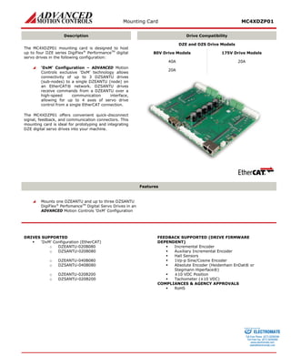
The MC4XDZP01 mounting card is designed to host up to four DZE series DigiFlex® PerformanceTM digital servo drives in the following configuration:
‘DxM’ Configuration – ADVANCED Motion Controls exclusive ‘DxM’ technology allows connectivity of up to 3 DZSANTU drives (sub-nodes) to a single DZEANTU (node) on an EtherCAT® network. DZSANTU drives receive commands from a DZEANTU over a high-speed communication interface, allowing for up to 4 axes of servo drive control from a single EtherCAT connection.
The MC4XDZP01 offers convenient quick-disconnect signal, feedback, and communication connectors. This mounting card is ideal for prototyping and integrating DZE digital servo drives into your machine.
DZE and DZS Drive Models
80V Drive Models
175V Drive Models
40A
20A
20A
Features
Mounts one DZEANTU and up to three DZSANTU DigiFlex® PerfomanceTM Digital Servo Drives in an ADVANCED Motion Controls ‘DxM’ Configuration
DRIVES SUPPORTED
‘DxM’ Configuration (EtherCAT)
o DZEANTU-020B080
o DZSANTU-020B080
o DZEANTU-040B080
o DZSANTU-040B080
o DZEANTU-020B200
o DZSANTU-020B200
FEEDBACK SUPPORTED (DRIVE FIRMWARE DEPENDENT)
Incremental Encoder
Auxiliary Incremental Encoder
Hall Sensors
1Vp-p Sine/Cosine Encoder
Absolute Encoder (Heidenhain EnDat® or Stegmann Hiperface®)
±10 VDC Position
Tachometer (±10 VDC)
COMPLIANCES & AGENCY APPROVALS
RoHS
ELECTROMATE
Toll Free Phone (877) SERVO98
Toll Free Fax (877) SERV099
www.electromate.com
sales@electromate.com
Sold & Serviced By:
2. Mounting Card MC4XDZP01
BLOCK DIAGRAM AND SPECIFICATION SUMMARY
I/O Axis 3I/O Axis 2I/O Axis 0AuxFeedbackAxis 3AuxFeedbackAxis 2AuxFeedbackAxis 0USBCANopenEtherCATFeedbackAxis 3FeedbackAxis 2Motor PowerAxis 3Motor PowerAxis 2FeedbackAxis 1FeedbackAxis 0Motor PowerAxis 1Motor PowerAxis 0Logic DZEANTUGNDHVMOTOR AMOTOR BMOTOR CGROUNDDC POWER INPUTLOGIC SUPPLY INPUTGROUNDTX+ TX- RX+ RX- CAN_LOWGROUNDCAN_HIGHVBUSDATA- USB GNDDATA+ PDI-1,2,3PDI-4,5 + PDI-4,5 – PDO-1,2,3,4,5PAI-1 + (REF+) PAI-1 – (REF-) AUX ENC A,B,I- AUX ENC A,B,I+ MOT ENC A,B,I+ / SIN+ / COS+ MOT ENC A,B,I- / SIN - / COS- HALL A,B,CMOT ENC DATA+ / CLOCK+ MOT ENC DATA- / CLOCK- MOTOR THERMISTORMC4XDZP01 MOUNTING CARDAXIS 1AXIS 0AXIS 2AXIS 3AUX ENC A,B,I- AUX ENC A,B,I+ PDI-1,2,3PDI-4,5 + PDI-4,5 – PDO-1,2,3,4,5PAI-1 + (REF+) PAI-1 – (REF-) PDI-1,2,3PDI-4,5 + PDI-4,5 – PDO-1,2,3,4,5PAI-1 + (REF+) PAI-1 – (REF-) AUX ENC A,B,I- AUX ENC A,B,I+ MOTOR AMOTOR BMOTOR CMOTOR AMOTOR BMOTOR CMOTOR AMOTOR BMOTOR CMOT ENC A,B,I+ / SIN+ / COS+ MOT ENC A,B,I- / SIN - / COS- HALL A,B,CMOT ENC DATA+ / CLOCK+ MOT ENC DATA- / CLOCK- MOTOR THERMISTORMOT ENC A,B,I+ / SIN+ / COS+ MOT ENC A,B,I- / SIN - / COS- HALL A,B,CMOT ENC DATA+ / CLOCK+ MOT ENC DATA- / CLOCK- MOTOR THERMISTORMOT ENC A,B,I+ / SIN+ / COS+ MOT ENC A,B,I- / SIN - / COS- HALL A,B,CMOT ENC DATA+ / CLOCK+ MOT ENC DATA- / CLOCK- MOTOR THERMISTOR AuxFeedbackAxis 1 AUX ENC A,B,I- AUX ENC A,B,I+ I/O Axis 1 PDI-1,2,3PDI-4,5 + PDI-4,5 – PDO-1,2,3,4,5PAI-1 + (REF+) PAI-1 – (REF-) DZSANTUDZSANTUDZSANTU CAN BITRATE01 0123456789ABCDEF
Mechanical Specifications
Mounting Signal Connectors (4): Mates Directly to Drive
96-port (Axis 0) / 68-port (Axis 1/2/3), 1.27mm spaced, dual-row socket
Mounting Power Connector (4): Mates Directly to Drive
50-pin, 2.0mm spaced, dual-row socket
Motor Power Connectors: MOTOR POWER 0/1/2/3
4-port screw terminal
Power Connector: HV
2 Individual threaded terminals
Auxiliary Logic Connector: LOGIC
2-port, 5.08 mm spaced, enclosed, friction lock header
EtherCAT Communication Connector: ETHERCAT IN/OUT
Shielded, dual RJ-45 socket with LEDs
CANopen Communication Connector: CANOPEN
Shielded, dual RJ-45 socket with LEDs
USB Connector: USB
5-pin, Mini USB B Type port
I/O Connectors: I/O 0/1/2/3*
20-pin, dual-row, 2.00 mm spaced plug terminal, horizontal mount
Auxiliary Feedback Connectors: AUX 0/1/2/3*
10-pin, dual-row, 2.00 mm spaced plug terminal, horizontal mount
Feedback Connectors: FB 0/1/2/3*
20-pin, dual-row, 2.00 mm spaced plug terminal, horizontal mount
Bus Capacitance
500 μF / 200V
Size (L x W x H) mm (in)
241.30 x 190.50 x 25 (9.5 x 7.5 x 0.98)
Weight
TBD
*Mating Connector Kit
Mating connector housing and crimp pins can be ordered as a kit using ADVANCED Motion Controls part number KC-MC4XDZP01. This includes mating connector housing and crimp style contacts for the I/O, Feedback, and Auxiliary Feedback connectors. The KC-MC4XDZP01 kit includes mating hardware for 1 axis only; to order mating hardware for all 4 axes, kit order quantity should be 4. The recommended tool for crimping the contacts is Molex part number 63811-6300. ELECTROMATE
Toll Free Phone (877) SERVO98
Toll Free Fax (877) SERV099
www.electromate.com
sales@electromate.com
Sold & Serviced By:
3. Mounting Card MC4XDZP01
Network Configurations and Axis Population
The table below shows the configuration options and axis population requirements for the MC4XDZP01. Note that populating axes 1, 2, and 3 is not required. The MC4XDZP01 can operate as a node in an EtherCAT network with only a DZEANTU drive installed in the Axis 0 slot if desired. When operating the MC4XDZP01 in a multi-axis configuration, note that only Axis 0 and Axis 1 are used for two-axis control; Axis 0, Axis 1, and Axis 2 are used for three-axis control; and Axis 0, Axis 1, Axis 2, and Axis 3 are used for four-axis control.
Single-Axis
Two-Axis
Three-Axis
Four-Axis
Network
Axis 0 (required)
Axis 1 (optional)
Axis 2 (optional)
Axis 3 (optional)
‘DxM’ Configuration (EtherCAT)
DZEANTU
DZSANTU
DZSANTU
DZSANTU
Single-Axis Two-Axis
Three-Axis Four-Axis
Status LED Functions
The MC4XDZP01 contains status LEDs that indicate DC Power Supply status, Logic Power Supply status, and the drive Bridge status. The Power LED will light up green when power is applied to P5-Power Connector, and the Logic LED will light up green when the Logic Power is applied to P6-Auxiliary Logic Connector. The Bridge Status LED indicates the servo drive’s power bridge state, and will be green when the drive is enabled, and red when the drive is in a fault state.
ELECTROMATE
Toll Free Phone (877) SERVO98
Toll Free Fax (877) SERV099
www.electromate.com
sales@electromate.com
Sold & Serviced By:
4. Mounting Card MC4XDZP01
PIN FUNCTIONS
Mounting Signal Connectors
These connectors mate directly to the drive. Use caution when inserting/removing drive to avoid damaging drive pins! For pin functions refer to the drive datasheet.
Mounting Power Connectors
These connectors mate directly to the drive. Use caution when inserting/removing drive to avoid damaging drive pins! For pin functions refer to the drive datasheet.
MOTOR POWER 0/1/2/3 - Motor Power Connectors
Pin
Name
Description / Notes
I/O
1
MOTOR A
Motor Phase Outputs (16 A continuous maximum per axis)
O
2
MOTOR B
O
3
MOTOR C
O
4
CHS0 or CHS1
Shield Connection. CHS0 connected to Chassis 0 mounting hole, CHS1 connected to Chassis 1 mounting hole.
-
HV - Power Connector
Pin
Name
Description / Notes
I/O
1
HIGH VOLTAGE
DC Power Input (67 A continuous maximum)
I
2
GND
Ground
GND
LOGIC - Auxiliary Logic Connector
Pin
Name
Description / Notes
I/O
1
AUX LOGIC
Logic Supply Input
I
2
GND
Ground
GND
ETHERCAT IN/OUT - EtherCAT Communication Connectors
Pin
Name
Description / Notes
I/O
1
TX+
Transmit Line (100 Base TX)
I/O
2
TX-
I/O
3
RX+
Receive Line (100 Base TX)
I/O
4
RESERVED
Reserved
-
5
RESERVED
Reserved
-
6
RX-
Receive Line (100 Base TX)
I/O
7
RESERVED
Reserved
-
8
COMM CHASSIS
Cable shield. Internally connected to Comm Chassis mounting hole.
-
CANOPEN - CANopen Communication Connectors
Pin
Name
Description / Notes
I/O
1
CAN_H
CAN_H bus line (dominant high)
I
2
CAN_L
CAN_L bus line (dominant low)
I
3
CAN_GND
CAN Ground
GND
4
RESERVED
Reserved
-
5
RESERVED
Reserved
-
6
RESERVED
Reserved
-
7
CAN_GND
CAN Ground
GND
8
RESERVED
Reserved
-
USB - USB Communication Connector
Pin
Name
Description / Notes
I/O
1
VBUS
Supply Voltage
O
2
DATA -
USB Data -
I/O
3
DATA +
USB Data +
I/O
4
RESERVED
Reserved
-
5
USB GND
USB Ground
UGND
ELECTROMATE
Toll Free Phone (877) SERVO98
Toll Free Fax (877) SERV099
www.electromate.com
sales@electromate.com
Sold & Serviced By:
5. Mounting Card MC4XDZP01
I/O 0/1/2/3 - I/O Connectors
Pin
Name
Description
I/O
1
COMM CHASSIS
Shield Connection. Connected to Comm Chassis mounting hole.
-
2
RESERVED
Reserved
-
3
PDI-1
Programmable Digital Input 1
I
4
PDI-4+
High Speed Differential Programmable Digital Input 4
I
5
PDI-2
Programmable Digital Input 2
I
6
PDI-4-
High Speed Differential Programmable Digital Input 4
I
7
PDI-3
Programmable Digital Input 3
I
8
PDI-5+
High Speed Differential Programmable Digital Input 5
I
9
RESERVED
Reserved
-
10
PDI-5-
High Speed Differential Programmable Digital Input 5
I
11
PDO-1
Programmable Digital Output 1
O
12
RESERVED
Reserved
-
13
PDO-2
Programmable Digital Output 2
O
14
+5V OUT
+5V Output from Logic Supply
O
15
PDO-3
Programmable Digital Output 3
O
16
GND
Ground
GND
17
PDO-4
Programmable Digital Output 4
O
18
PAI-1+
Differential Programmable Analog Input or Reference Signal Input (12-bit resolution)
I
19
PDO-5
Programmable Digital Output 5
O
20
PAI-1-
Differential Programmable Analog Input or Reference Signal Input (12-bit resolution)
I
AUX 0/1/2/3 - Auxiliary Feedback Connectors
Pin
Name
Description
I/O
1
COMM CHASSIS
Shield Connection. Connected to Comm Chassis mounting hole.
-
2
RESERVED
Reserved
-
3
AUX ENC I+
Auxiliary Incremental Encoder Channel I or Differential Programmable Digital Input 8
I
4
AUX ENC A+
Auxiliary Incremental Encoder Channel A or Differential Programmable Digital Input 6
I
5
AUX ENC I-
Auxiliary Incremental Encoder Channel I or Differential Programmable Digital Input 8
I
6
AUX ENC A-
Auxiliary Incremental Encoder Channel A or Differential Programmable Digital Input 6
I
7
+5V USER
+5V User Supply Output (current shared with Pin-17 on Feedback Connector)
O
8
AUX ENC B+
Auxiliary Incremental Encoder Channel B or Differential Programmable Digital Input 7
I
9
GND
Ground
GND
10
AUX ENC B-
Auxiliary Incremental Encoder Channel B or Differential Programmable Digital Input 7
I
FB 0/1/2/3 - Feedback Connectors*
Pin
Incremental Encoder
Absolute Encoder
1Vp-p Sin/Cos Encoder
Description / Notes
I/O
1
CHS0 or CHS1
CHS0 or CHS1
CHS0 or CHS1
Shield Connection. FB 0 and FB 1 connected to Chassis 0 mounting hole, FB 2 and FB 3 connected to Chassis 1 mounting hole.
-
2
RESERVED
RESERVED
RESERVED
Reserved
-
3
MOT ENC I+
RESERVED
RESERVED
Differential Encoder Index
I
4
MOT ENC A+
SIN+
SIN+
Differential Encoder A / Differential Sine Input
I
5
MOT ENC I-
RESERVED
RESERVED
Differential Encoder Index
I
6
MOT ENC A-
SIN-
SIN-
Differential Encoder A / Differential Sine Input
I
7
HALL A
RESERVED
HALL A
Commutation sensor input.
I
8
MOT ENC B+
COS+
COS+
Differential Encoder B/ Differential Cosine Input
I
9
HALL B
RESERVED
HALL B
Commutation sensor input.
I
10
MOT ENC B-
COS-
COS-
Differential Encoder B/ Differential Cosine Input
I
11
HALL C
RESERVED
HALL C
Commutation sensor input.
I
12
RESERVED
RESERVED
RESERVED
Reserved
-
13
RESERVED
RESERVED
RESERVED
Reserved
-
14
RESERVED
MOT ENC CLK+
RESERVED
Differential Clock Line
I/O
15
MOTOR THERMISTOR
MOTOR THERMISTOR
MOTOR THERMISTOR
Motor Thermal Protection
I
16
RESERVED
MOT ENC CLK-
RESERVED
Differential Clock Line
I/O
17
+5V USER
+5V USER
+5V USER
+5V User Supply Output (current shared w/ Pin-7 on Aux Feedback Conn.)
O
18
RESERVED
MOT ENC DATA+
RESERVED
Differential Data Line
I/O
19
GND
GND
GND
Ground
GND
20
RESERVED
MOT ENC DATA-
RESERVED
Differential Data Line
I/O
*Note: Feedback supported (Incremental Encoder, Absolute Sin/Cos Encoder, or 1Vp-p Sin/Cos Encoder) will be dependent on drive firmware.
ELECTROMATE
Toll Free Phone (877) SERVO98
Toll Free Fax (877) SERV099
www.electromate.com
sales@electromate.com
Sold & Serviced By:
6. Mounting Card MC4XDZP01
BOARD CONFIGURATION
EtherCAT Communication LED Functions (on RJ-45 Communication Connectors)
LINK/ACTIVITY LED
LED State
Description
Green – On
Valid Link - No Activity
Green – Flickering
Valid Link - Network Activity
Off
Invalid Link
STATUS LED
LED State
Description
Green – On
The device is in the state OPERATIONAL
Green – Blinking (2.5Hz – 200ms on and 200ms off)
The device is in the state PRE-OPERATIONAL
Green – Single Flash (200ms flash followed by 1000ms off)
The device is in state SAFE-OPERATIONAL
Green – Flickering (10Hz – 50ms on and 50ms off)
The device is booting and has not yet entered the INIT state
or
The device is in state BOOTSTRAP
or
Firmware download operation in progress
Off
The device is in state INIT
ERROR LED
LED State
Description
Example
Red – On
A PDI Watchdog timeout has occurred.
Application controller is not responding anymore.
Red – Blinking (2.5Hz – 200ms on and 200ms off)
General Configuration Error.
State change commanded by master is impossible due to register or object settings.
Red – Flickering (10Hz – 50ms on and 50ms off)
Booting Error was detected. INIT state reached, but parameter “Change” in the AL status register is set to 0x01:change/error
Checksum Error in Flash Memory.
Red – Single Flash (200ms flash followed by 1000ms off)
The slave device application has changed the EtherCAT state autonomously: Parameter “Change” in the AL status register is set to 0x01:change/error.
Synchronization error; device enters SAFE- OPERATIONAL automatically
Red – Double Flash (Two 200ms flashes separated by 200ms off, followed by 1000ms off)
An application Watchdog timeout has occurred.
Sync Manager Watchdog timeout.
Mounting Card Address Switch
Switch Diagram
Description
0123 45678 9ABCDEF
Hexadecimal switch settings correspond to the drive Station Alias. Note that drives on an EtherCAT network will be given an address automatically based on proximity to the host. Setting the switches manually is optional, and only necessary if a fixed address is required.
Switch Setting
Node ID
0
000
1
016
2
032
…
…
D
208
E
224
F
240
ELECTROMATE
Toll Free Phone (877) SERVO98
Toll Free Fax (877) SERV099
www.electromate.com
sales@electromate.com
Sold & Serviced By:
7. Mounting Card MC4XDZP01
CONNECTOR INFORMATION
Mounting Signal Connectors
Connector Information
96-pin (Axis 0) / 68-pin (Axis 1/2/3), 1.27 mm spaced, dual-row socket
Mating Connector Example
No Mating Connector Required. Mate directly to drive
Mounting Power Connectors
Connector Information
50-pin, 2.0 mm spaced, dual-row socket
Mating Connector Example
No Mating Connector Required. Mate directly to drive
MOTOR POWER 0/1/2/3 - Motor Power Connectors
Connector Information
4-port screw terminal
Mating Connector
Details
Not Applicable
Included with Card
Not Applicable
CHS0 / CHS14MOTOR C3MOTOR B2MOTOR A1
HV - Power Connector
Connector Information
Bushings with M4 Screw
Mating Connector
Details
Not Applicable
Included with Card
Not Applicable
LOGIC - Auxiliary Logic Connector
Connector Information
2-port, 5.08 mm spaced, enclosed, friction lock header
Mating Connector
Details
Phoenix Contact: P/N 1757019
Included with Card
Yes
AUX LOGIC1GND2
ELECTROMATE
Toll Free Phone (877) SERVO98
Toll Free Fax (877) SERV099
www.electromate.com
sales@electromate.com
Sold & Serviced By:
8. Mounting Card MC4XDZP01
ETHERCAT IN/OUT - EtherCAT Communication Connectors
Connector Information
Shielded, dual RJ-45 socket with LEDs
Mating Connector
Details
CAT 5 Cable
Included with Card
No
TX+1RX+3TX+13INOUTRX+ TX-2RX-66RX- 2TX- LINKLINKSTATUS8SHIELDSHIELD8
CANOPEN - CANopen Communication Connectors
Connector Information
Shielded, dual RJ-45 socket with LEDs
Mating Connector
Details
CAT 5 Cable
Included with Card
No
CAN_H1CAN_GND3CAN_H13CAN_GNDCAN_L2CAN_GND77CAN_GND2CAN_L
USB - USB Connector
Connector Information
5-pin, Mini USB B Type port
Mating Connector
Details
TYCO: 1496476-3 (2-meter STD-A to MINI-B ASSY)
Included with Card
No
1VBUS2DATA - 3DATA + 4RESERVED5USB GND
ELECTROMATE
Toll Free Phone (877) SERVO98
Toll Free Fax (877) SERV099
www.electromate.com
sales@electromate.com
Sold & Serviced By:
9. Mounting Card MC4XDZP01
I/O 0/1/2/3 - I/O Connectors
Connector Information
20-pin, dual-row, 2.00 mm spaced plug terminal, horizontal mount
Mating Connector
Details
Molex: P/N 51353-2000 (housing); 56134-9100 (contacts)
Included with Card
No
1COMM CHASSIS3PDI-15PDI-27PDI-39RESERVED2RESERVED4PDI-4+ 6PDI-4- 8PDI-5+ 10PDI-5- 20PAI-1- 18PAI-1+ 16GND14+5V OUT12RESERVED19PDO-517PDO-415PDO-313PDO-211PDO-1
AUX 0/1/2/3 - Auxiliary Feedback Connectors
Connector Information
10-pin, dual-row, 2.00 mm spaced plug terminal, horizontal mount
Mating Connector
Details
Molex: P/N 51353-1000 (housing); 56134-9100 (contacts)
Included with Card
No
1COMM CHASSIS3AUX ENC I+ 5AUX ENC I- 2RESERVED4AUX ENC A+ 6AUX ENC A- 10AUX ENC B- 8AUX ENC B+ 9GND7+5V USER
FB 0/1/2/3 - Feedback Connectors
Connector Information
20-pin, dual-row, 2.00 mm spaced plug terminal, horizontal mount
Mating Connector
Details
Molex: P/N 51353-2000 (housing); 56134-9100 (contacts)
Included with Card
No
1CHS0 / CHS13MOT ENC I+ 5MOT ENC I- 7HALL A9HALL B2RESERVED4MOT ENC A+ 6MOT ENC A- 8MOT ENC B+ 10MOT ENC B- 20RESERVED18GROUND16RESERVED14RESERVED12RESERVED19GND17+5V USER15MOTOR THERMISTOR13RESERVED11HALL C 1CHS0 / CHS13RESERVED5RESERVED7RESERVED9RESERVED2RESERVED4SIN+ 6SIN- 8COS+ 10COS- 20MOT ENC DATA- 18MOT ENC DATA+ 16MOT ENC CLK- 14MOT ENC CLK+ 12RESERVED19GND17+5V USER15MOTOR THERMISTOR13RESERVED11RESERVED 1CHS0 / CHS13RESERVED5RESERVED7HALL A9HALL B2RESERVED4SIN+ 6SIN- 8COS+ 10COS- 20RESERVED18RESERVED16RESERVED14RESERVED12RESERVED19GND17+5V USER15MOTOR THERMISTOR13RESERVED11HALL C
Incremental Encoder Absolute Encoder 1Vp-p Sin/Cos Encoder
ELECTROMATE
Toll Free Phone (877) SERVO98
Toll Free Fax (877) SERV099
www.electromate.com
sales@electromate.com
Sold & Serviced By:
11. Mounting Card MC4XDZP01
PART NUMBERING INFORMATION
XDrive Type IndicatorDZP: DZ Digiflex PerformanceAxisNumber of axes supportedProduct TypeMC indicates mounting cardSeriesMounting card seriesMC4DZP01
DigiFlex® Performance™ series of products are available in many configurations. All models listed in the selection tables of the website are readily available, standard product offerings.
ADVANCED Motion Controls also has the capability to promptly develop and deliver specified products for OEMs with volume requests. Our Applications and Engineering Departments will work closely with your design team through all stages of development in order to provide the best servo drive solution for your system. Equipped with on-site manufacturing for quick- turn customs capabilities, ADVANCED Motion Controls utilizes our years of engineering and manufacturing expertise to decrease your costs and time-to-market while increasing system quality and reliability.
Examples of Customized Products
Optimized Footprint
Tailored Project File
Private Label Software
Silkscreen Branding
OEM Specified Connectors
Optimized Base Plate
No Outer Case
Increased Current Limits
Increased Current Resolution
Increased Voltage Range
Increased Temperature Range
Conformal Coating
Custom Control Interface
Multi-Axis Configurations
Integrated System I/O
Reduced Profile Size and Weight
Feel free to contact Applications Engineering for further information and details.
All specifications in this document are subject to change without written notice. Actual product may differ from pictures provided in this document.
ELECTROMATE
Toll Free Phone (877) SERVO98
Toll Free Fax (877) SERV099
www.electromate.com
sales@electromate.com
Sold & Serviced By: