Download to read offline
![Kaleemullah et al. Int. Journal of Engineering Research and Application www.ijera.com
ISSN : 2248-9622, Vol. 6, Issue 6, ( Part -4) June 2016, pp.01-08
www.ijera.com 1 | P a g e
Adaptive Fuzzy PID Based Control Strategy For 3Phase 4Wire
Shunt Active Filter To Mitigate Current Harmonics Of Grid
Interconnection Of Renewable Energy Based Distribution System
Kaleemullah1
*, Amjad Khan2
**, Dr. Muhammad Naeem Arbaab3
***
12
PG Research student, Dept. of EEE, University of Engineering and technology Peshawar, KP, Pakistan,
3
Research Scholar, Dept. of EEE, University of Engineering and technology Peshawar, KP, Pakistan
ABSTRACT
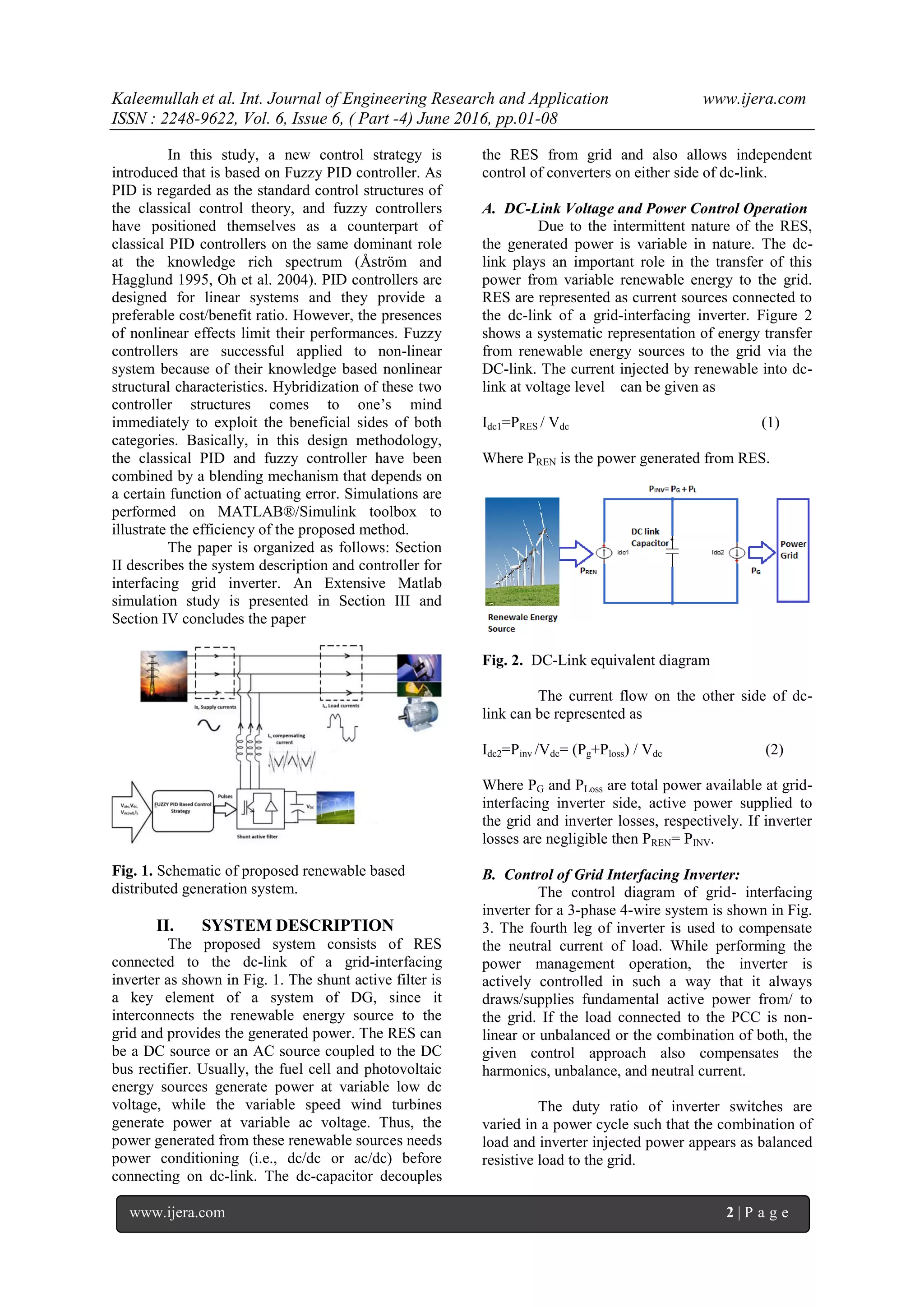
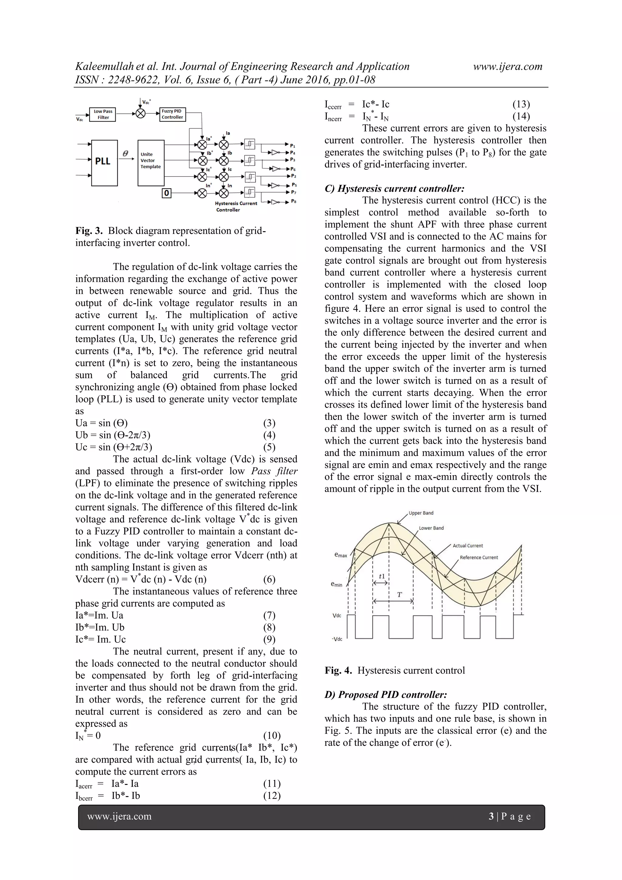
This paper presents a new control strategy for controlling the shunt active power filter to compensate reactive
power and to reduce the unwanted harmonics in the grid current. Shunt active filter act as a current source which
is connected in parallel with a non-linear load and controlled to produce the required compensating current. The
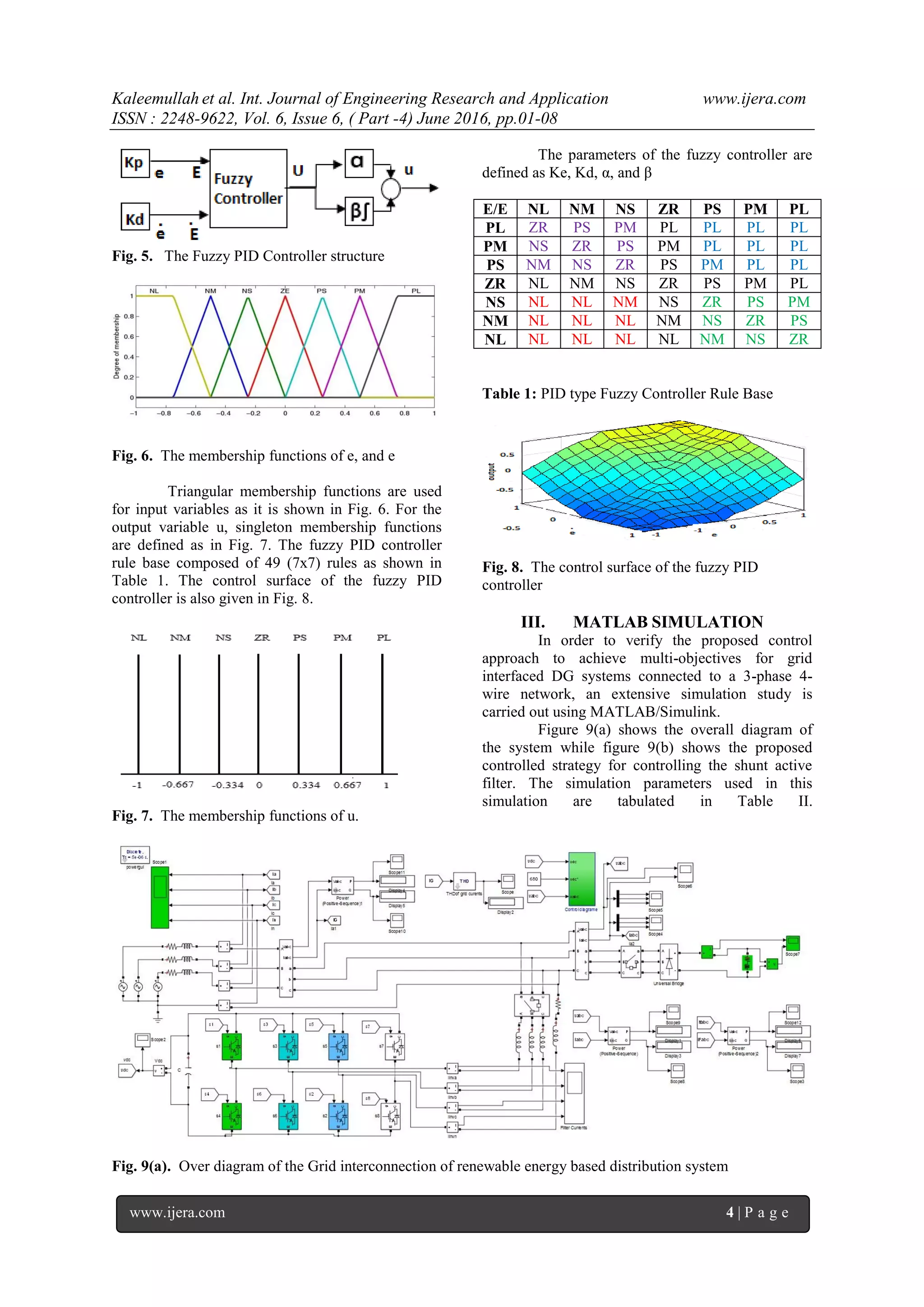
proposed control strategy is based on the fuzzy PID controller which is used for determining the reference
compensating currents of the three-phase shunt active power filters. Simulations are carried out using
MATLAB/SIMULINK to verify the performance of the proposed controller. The output shows the controller has
fast dynamic response high accuracy of tracking DC voltage reference and robust to load parameters variations.
Index Terms: Active power filter (APF), fuzzy controller, Fuzzy PID controller, distributed generation (DG),
distribution system, grid interconnection
I. INTRODUCTION
The non-renewable- energy decreases at a
faster pace has made renewable energy as a future
energy source. Renewable energy-based power
generation systems has many advantages such as the
development of clean energy, reduce global
warming etc. But on the other hand, renewable
energy intermittently when it is directly connected to
the grid caused many power quality issues such as
harmonics, voltage sags, break etc. [1].The
distributed generation schemes are widely uses
power electronic interface for grid connections,
because of its fast response, harmonic compensation
and reactive power compensation. Due to the
widespread use of non-linear loads large amounts of
harmonic currents are injected into the power
systems. These harmonic currents flowing through
the impedance of the supply system causing
harmonic currents to pull by other loads connected
to the PCC. The persistence of current harmonics
and voltage in the power system increases the losses
in the lines, decrease the power factor and may cause
timing errors in sensitive electronic equipment.
Three phases balanced non-linear loads such as
motor drivers, silicon controlled rectifiers (SCR),
large uninterruptible power supplies (UPS) produce
harmonic currents and voltages that are harmonics of
positive sequence as 7th, 13th, etc. and negative-
sequence harmonics like 5th, 11th, etc. Single phase
non-linear loads such as switch-mode power
supplies in computer equipment produce harmonic
currents and voltages which are third order zero-
sequence harmonics, triplen harmonics like 3rd, 9th,
15th, 21st, etc. Unlike positive and negative-
sequence harmonic currents, triplen harmonic
currents do not cancel but add arithmetically at the
neutral bus. This result’s the neutral current that
touches magnitudes as high as 1.73 times the phase
current. In addition to the risk of cables and
transformers overheating, the third harmonic can
recede energy efficiency [2]. The method of current
harmonics reduction reduces passive LC filters
which are simple and low cost. However, these
filters have drawbacks as well like large size, tuning
and risk of resonance problems. As harmonic
pollution is severe in power networks, power system
engineer developed dynamic and adjustable
solutions to the power quality problems. Such
equipment is known as Active Filters (AF’s) [3].
These filters are used to compensate the load current
harmonics and improve the power factor.
In addition to eliminating the harmonic
currents and improving the power factor, SAF can
maintain the balance of electrical system under the
unbalanced load condition and nonlinear loads [4-6].
In general, the performance of SAF is based on three
design criteria [7-12]: i) the design of the power
inverter; ii) the types of current regulators used; iii)
the methods used to obtain the reference current.
Several control techniques have been used to obtain
the reference current. These techniques such as the
theory of instantaneous reactive power [7], notch
filters [9], the control flow based [10], the theory of
balance of power [9] - [13], and the controller
sliding mode have been used to improve the
performance of active filters. However, most of
these control techniques include a number of
transformations and are difficult to implement.
RESEARCH ARTICLE OPEN ACCESS](https://image.slidesharecdn.com/a0606040108-160811072109/75/Adaptive-Fuzzy-PID-Based-Control-Strategy-For-3Phase-4Wire-Shunt-Active-Filter-To-Mitigate-Current-Harmonics-Of-Grid-Interconnection-Of-Renewable-Energy-Based-Distribution-System-1-2048.jpg)
![Kaleemullah et al. Int. Journal of Engineering Research and Application www.ijera.com
ISSN : 2248-9622, Vol. 6, Issue 6, ( Part -4) June 2016, pp.01-08
www.ijera.com 8 | P a g e
REFERENCES
[1]. H. R. Enslin and P. 1. M. Heskes,
"Harmonic interaction between a large
number of distributed power inverters and
the distribution network, "IEEE Trans.
Power Electron., vol. 19, no. 6, pp. 1586-
1593.Nov. 2004.
[2]. Recommended Practices and Requirements
for Harmonic Control in Electrical Power
System, IEEE 519-1992
[3]. António Martins , José Ferreira and Helder
Azevedo” Active Power Filters for
Harmonic Elimination and Power Quality
Improvement” DOI: 10.5772/13882
[4]. Chandra,A., Singh,B., Al-Haddad,K., An
improved control algorithm of shunt active
filter for voltage regulation, harmonic
elimination, power-factor correction, and
balancing of nonlinear loads. IEEE
Transaction on Power Electronics 2000; 15
(6): 495-503.
[5]. Buso,S., Malesani,L., Mattavelli,P.,
Veronese,R. Design and fully digital
control of parallel active filters for
thyristor rectifiers to comply with IEC-
1000-3-2 standards,” IEEE Transactions on
Industry Applications 1998; 34 (3): 508-
517.
[6]. Fujita,H., Akagi,H., The unified power
quality conditioner: the integration of
series-and shunt-active filters. IEEE
Transactions on Power Electronics 1998;
13 (2): 577-584.
[7]. Akagi,H., Kanazawa,Y., Nabae,A.,
Instantaneous reactive power compensators
comprising switching devices without
energy storage components. IEEE
Transactions on Industry Applications
1984; IA-20: 625-630.
[8]. Singh,B., Al-Haddad,K., Chandra,A.,
Active power filter with sliding mode
control. In: proc. Inst. Elect. Eng.,
Generation Transm. Distrib. 1997;144:
564-568
[9]. Rastogi,M., Mohan,N., Edris,A., Hybrid-
active power filtering of harmonic currents
in power systems. IEEE Transactions on
Power Delivery 1995; 10 (3): 1994-2000.
[10]. Bhattacharya,S., Veliman,A., Divan,A.,
Lorenz,R. Flux based active power filter
controller. In: Proc. IEEE-IAS Annual
Meeting Record, 1995; 2483-2491.
[11]. Jou,H., Performance compression of the
three- phase active power filter algorithms.
In: proc. Inst. Elect. Eng., Generation
Transm. Distrib. 1995; 142: 646-652.
[12]. Dixon,J., Garcia,J., Moran,I., Control
system for three-phase active power filter
which simultaneously compensates power
factor and unbalanced loads. IEEE
Transactions on Industrial Electronics
1995; 42 (6): 636-641.
[13]. Barbosa,P., Santisteban,J., Watanabe,E.,
Shunt- series active power filter for
rectifier's ac and dc sides. IEE Proc.-
Electrical Power Application 1998; 145
(6): 577-584.
[14]. Peng,F.,Harmonic source and filtering
approaches. IEEE Transactions on industry
applications 2001;7(4): 18-25
Kaleem ullah received the B.Sc degree
from the Department of Electrical and
Electronics, University of Engineering and
Technology Peshawar, Khyber
Pakhtunkhwa, Pakistan in 2013.He is doing
his Master from the same University with
specialization in Electrical Power. His
research deal with the power quality
problem in transmission lines and with
distributed generation. His e-mail address is
Kaleem.icpp1366@gmail.com
Amjad khan received the B.Sc degree
from the Department of Electrical and
Electronics, University of Engineering and
Technology Peshawar, Khyber
Pakhtunkhwa, Pakistan, in 2013.He is
doing his Master from the same University
with specialization in Electrical Power. His
research interests are in Distributed
generation. His e-mail address is
k_amjad461@yahoo.com
Dr Muhammad Naeem Arbab received
the B.Sc degree from the Department of
Electrical and Electronics, University of
Engineering and Technology Peshawar,
Khyber Paktun Khwa, Pakistan, in 1989
and M.S. and Ph.D. degrees from
University of Manchester, UK. He is
currently a professor in Department of
Electrical Engineering of UET Peshawar.
His email address is mnarbab@yahoo.com](https://image.slidesharecdn.com/a0606040108-160811072109/75/Adaptive-Fuzzy-PID-Based-Control-Strategy-For-3Phase-4Wire-Shunt-Active-Filter-To-Mitigate-Current-Harmonics-Of-Grid-Interconnection-Of-Renewable-Energy-Based-Distribution-System-8-2048.jpg)

The document presents a new control strategy for controlling a shunt active power filter to compensate for reactive power and reduce current harmonics in a grid connected to a renewable energy based distribution system. The proposed control strategy uses a fuzzy PID controller to determine the reference compensating currents for a three-phase shunt active power filter. Simulations in MATLAB/Simulink show that the controller has fast dynamic response, accurately tracks the DC voltage reference, and is robust to load parameter variations. The fuzzy PID controller hybridizes classical PID and fuzzy control to exploit the benefits of both.