Downloaded 13 times
![K Srinivas, B Subash / International Journal of Engineering Research and Applications
(IJERA) ISSN: 2248-9622 www.ijera.com
Vol. 2, Issue 6, November- December 2012, pp.1636-1640
Fig. Simulation results: (a) PQ-Grid, (b) PQ-
Load, (c) PQ-Inverter,(d) dc-link voltage.
REFERENCES
[1] J. M. Guerrero, L. G. de Vicuna, J. Matas,
M. Castilla, and J. Miret,“A wireless
controller to enhance dynamic performance
of parallel invertersin distributed generation
systems,” IEEE Trans. Power
Electron.,[2]vol. 19, no. 5, pp. 1205–1213,
Sep. 2004.
(2) J. P. Pinto, R. Pregitzer, L. F. C. Monteiro,
and J. L. Afonso, “3-phase4-wire shunt
active power filter with renewable energy
interface,” presented at the Conf. IEEE
Rnewable Energy & Power Quality, Seville,
Spain, 2007.
[3] F. Blaabjerg, R. Teodorescu, M. Liserre, and
A. V. Timbus, “Overview of control and grid
synchronization for distributed power
generation systems,” IEEE Trans. Ind.
Electron., vol. 53, no. 5, pp. 1398–1409,
Oct. 2006
[4] M. Singh and A. Chandra, “Power maximization
and voltage sag/swell ride-through capability of
PMSG based variable speed wind energy
conversion system,” in Proc. IEEE 34th Annu.
Conf. Indus. Electron. Soc., 2008, pp. 2206–2211
.
Fig. Simulation results: (a) Grid voltages, (b) Grid .
Currents (c) Unbalanced
load currents, (d) Inverter Current
1640 | P a g e](https://image.slidesharecdn.com/il2616361640-121222002310-phpapp01/75/Il2616361640-5-2048.jpg)

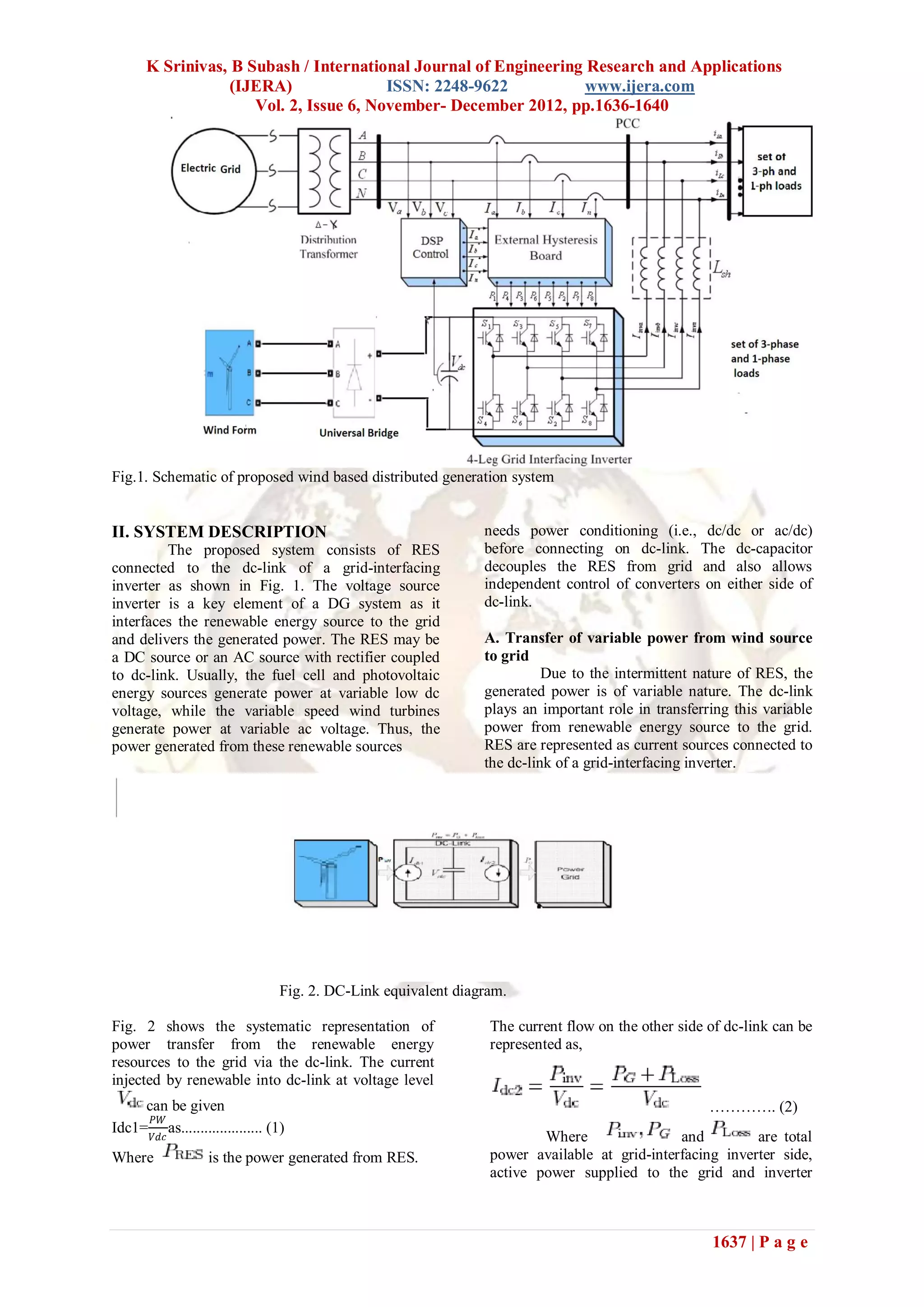
1) The document presents a control strategy for a grid-interfacing inverter connected to renewable energy sources to improve power quality at the distribution level grid connection point. 2) By controlling the inverter, it can act as both a power converter to inject renewable power into the grid and as an active power filter to compensate for current unbalance, load harmonics, reactive power demand, and neutral current without additional hardware costs. 3) The control strategy aims to maximize utilization of the inverter rating and allows the inverter and nonlinear/unbalanced load at the point of common coupling to appear as a balanced linear load to the grid, maintaining power quality standards.