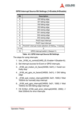
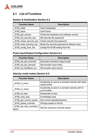
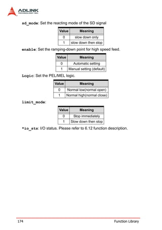
Here are the key features of the PCI-8158 motion control card:
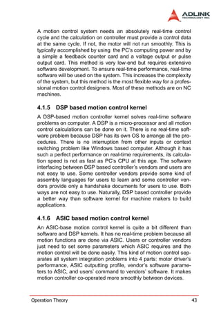
- 8 axes of pulse output control for stepper or servo motors up to 6.55 million pulses per second (MPPS) per axis.
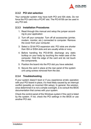
- Programmable acceleration/deceleration profiles including trapezoidal and S-curve.
- Linear and circular interpolation for up to 4 axes and continuous motion contouring.
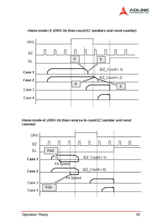
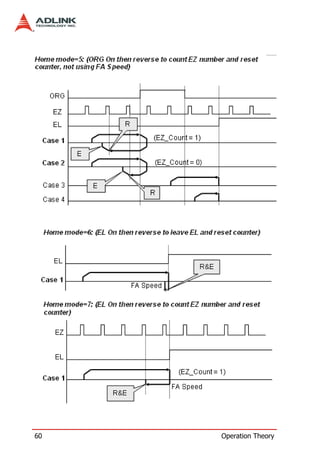
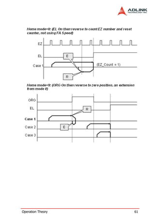
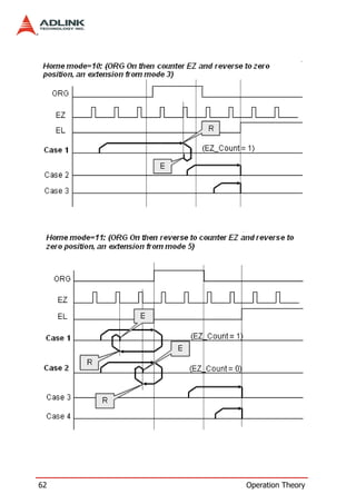
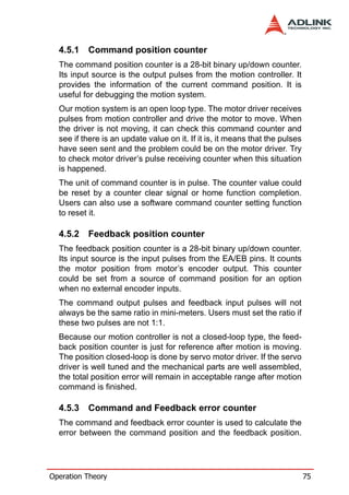
- 13 home search modes with automatic encoder index search.
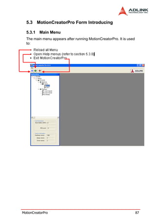
- Hardware backlash compensation and vibration suppression.
- Encoder feedback interface with 28-bit up/down counters.
- End limit, home, and general purpose digital I/O on each axis.
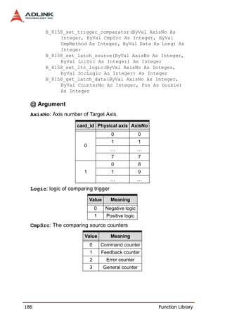
- Position compare and trigger output
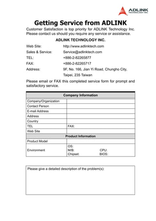

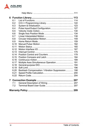

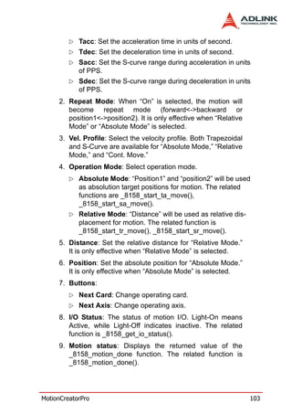
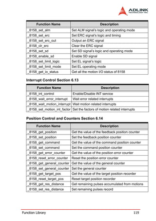
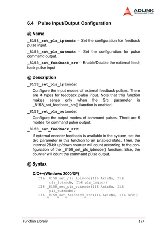
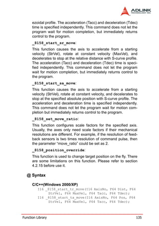
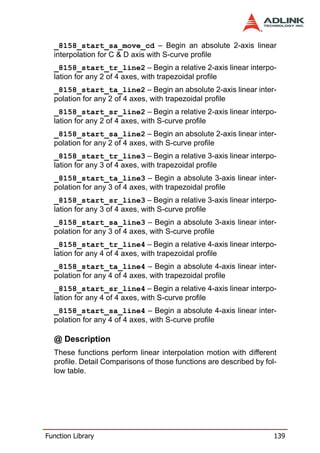
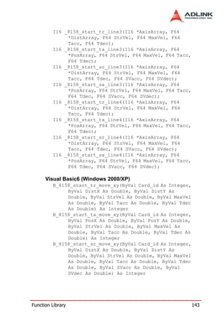
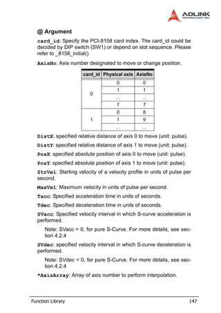
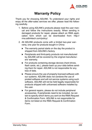
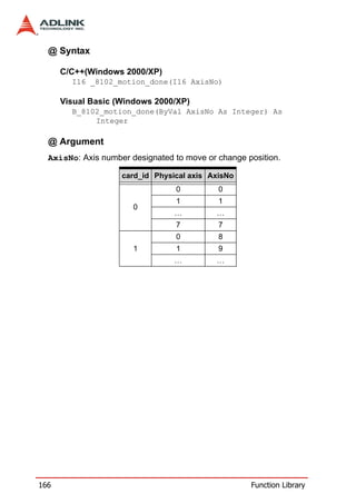
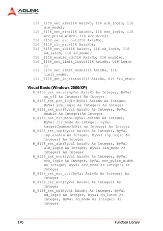
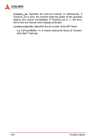
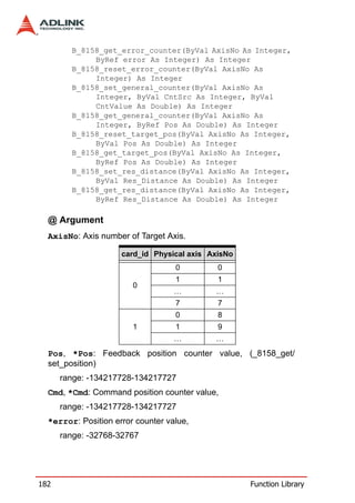
![Example: I16 AxisArray[2] = {0, 3}; //axis 0, & axis 3 (correct)
I16 AxisArray[3] = {0,2, 3}; //axis 0, 2 & 3 (correct)
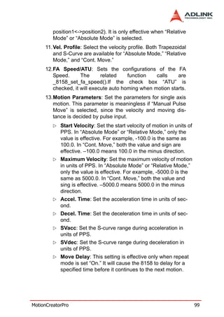
I16 AxisArray[2] = {1, 6}; //axis 1, & axis 6 (incorrect)
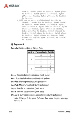
*DistArray: Array of relative distance for linear interpolation.
Example: I16 AxisArray[2] = {0, 3}; //axis 0, & axis 3
F64 DistArray[2] = {1000.0, 2000.0} //for axis 0 & 3
*PosArray: Array of absolute position for linear interpolation.
Example: I16 AxisArray[3] = {0,2, 3}; //axis 0, 2 & 3
F64 PosArray[3] = {200.0, 300.0, 400.0} //absolute position
for axis 0, 2 & 3
148 Function Library](https://image.slidesharecdn.com/pci-8158manual10-120311204859-phpapp01/85/Pci-8158-manual-10-158-320.jpg)
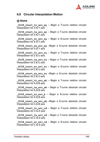
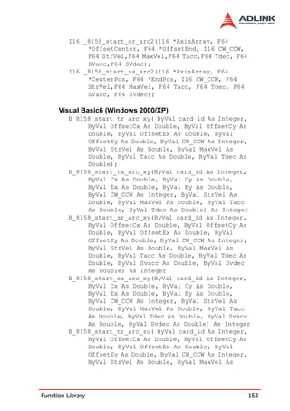
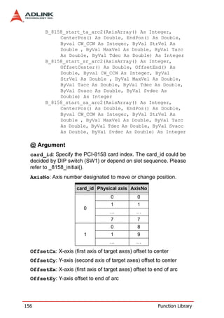
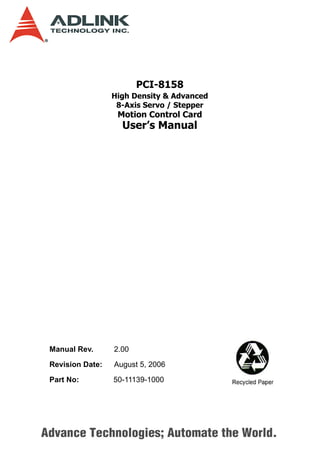
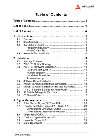
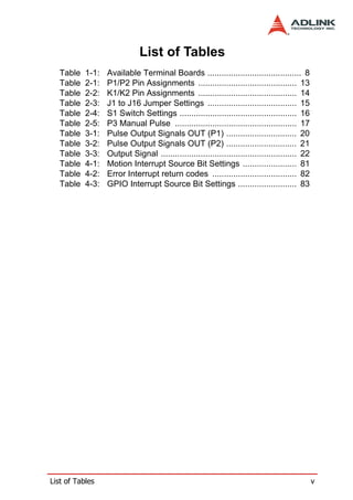
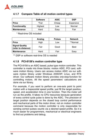
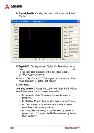
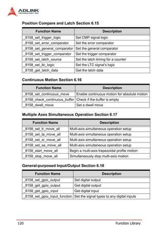
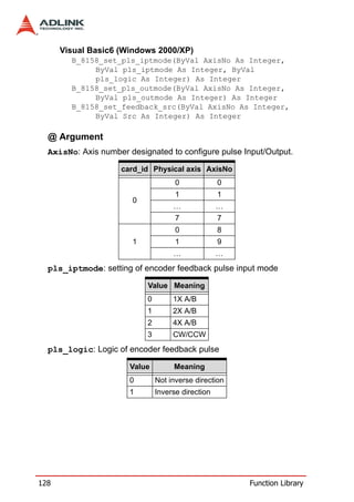
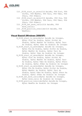
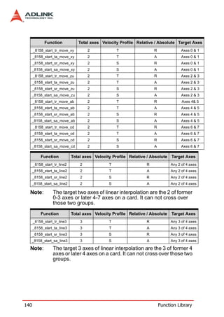
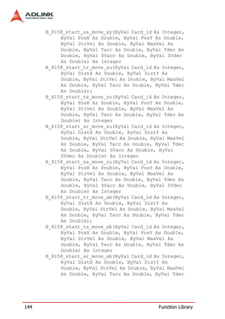
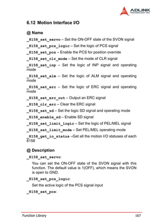
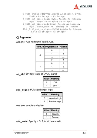
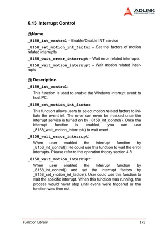
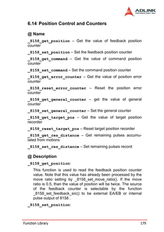
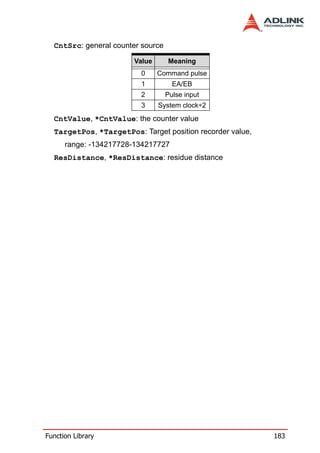
![Cx : X-axis (first axis of target axes) absolute position of center of
arc
Cy: Y-axis (second axis of target axes) absolute position of center
of arc
Ex: X-axis (first axis of target axes) absolute position of end of arc
Ey: Y-axis (second axis of target axes) absolute position of end of
arc
CW_CCW: Specified direction of arc
Value Meaning
0 Clockwise(cw)
1 Counterclockwise(ccw)
StrVel: Starting velocity of a velocity profile in units of pulse per
second.
MaxVel: Maximum velocity in units of pulse per second.
Tacc: Specified acceleration time in units of seconds.
Tdec: Specified deceleration time in units of seconds.
SVacc: Specified velocity interval in which S-curve acceleration is
performed.
Note: SVacc = 0, for pure S-Curve. For more details, see sec-
tion 4.2.4
SVdec: specified velocity interval in which S-curve deceleration is
performed.
Note: SVdec = 0, for pure S-Curve. For more details, see sec-
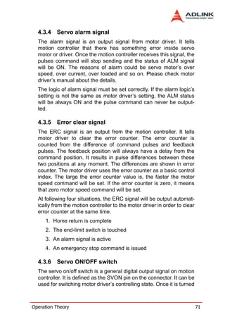
tion 4.2.4
*AxisArray: Array of axis number to perform interpolation.
Example: I16 AxisArray[2] = {0, 3}; //axis 0, & axis 3 (correct)
I16 AxisArray[2] = {1, 6}; //axis 1, & axis 6 (incorrect)
*OffsetCenter: Array of the offset to center (relative to the start
position)
Example: F64 OffsetCenter[2] = {2000.0, 0.0}; //offset from
start position(initial point) for 1st & 2nd axes
Function Library 157](https://image.slidesharecdn.com/pci-8158manual10-120311204859-phpapp01/85/Pci-8158-manual-10-167-320.jpg)
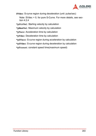
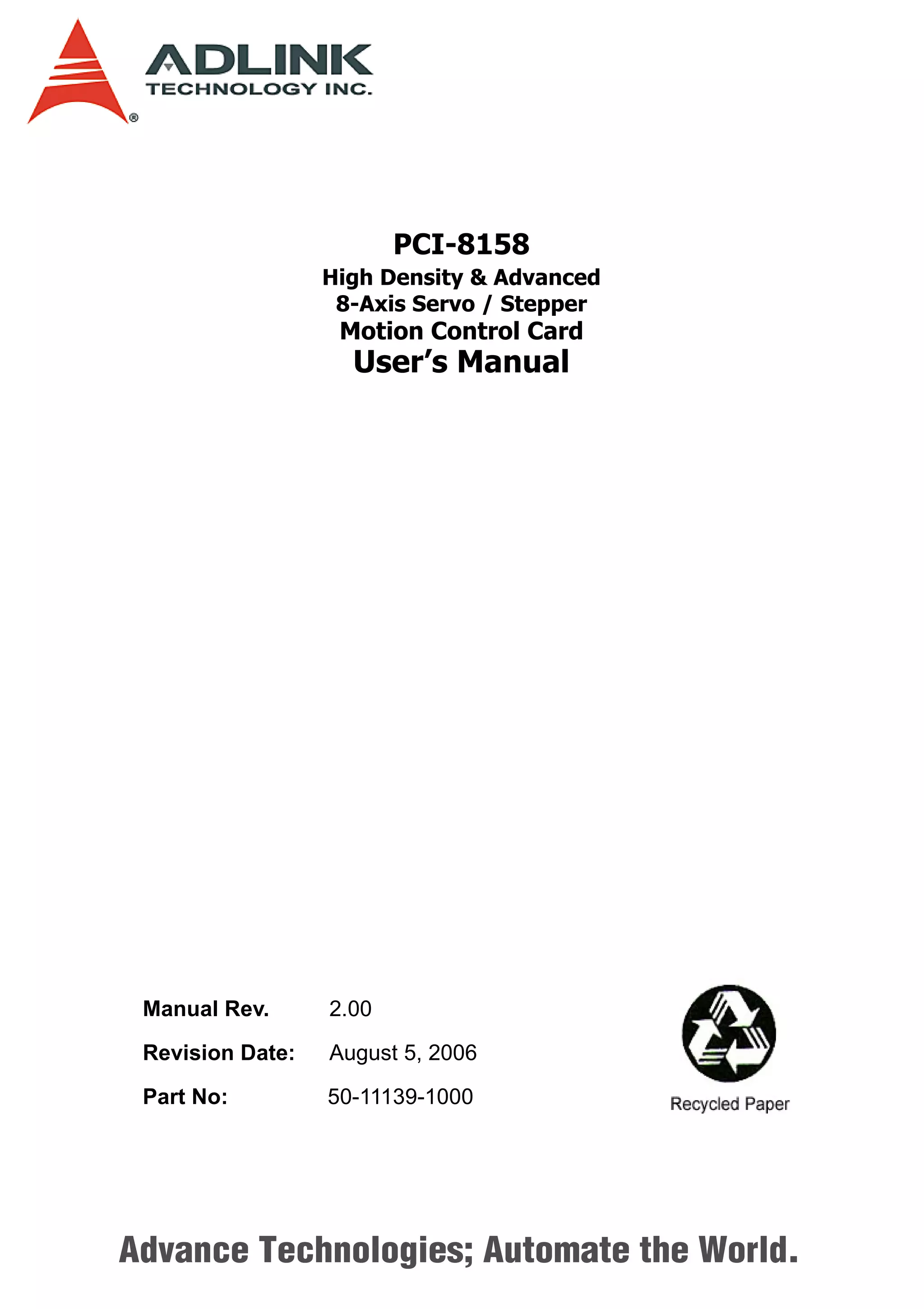
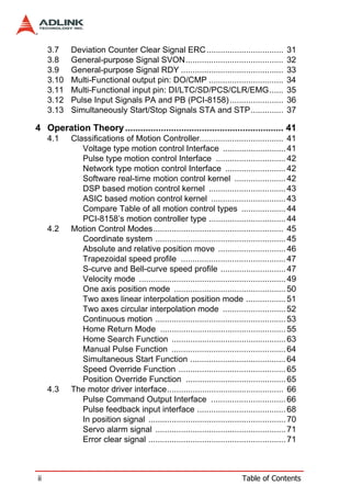
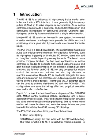
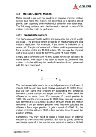
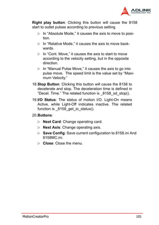
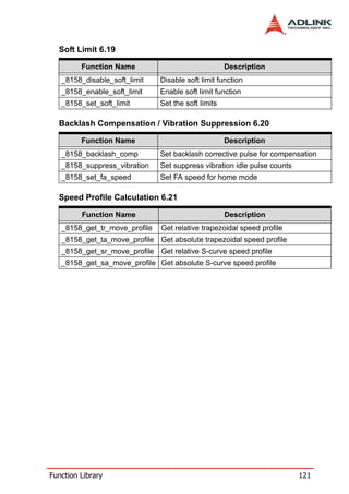
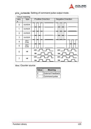
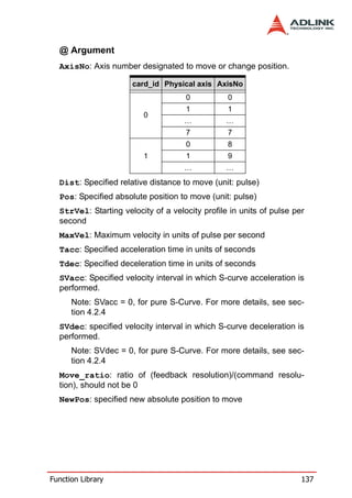
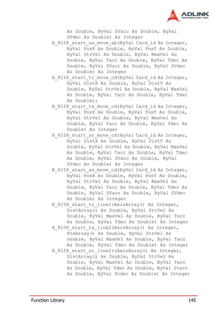
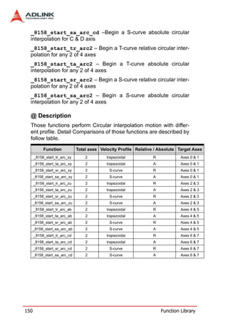
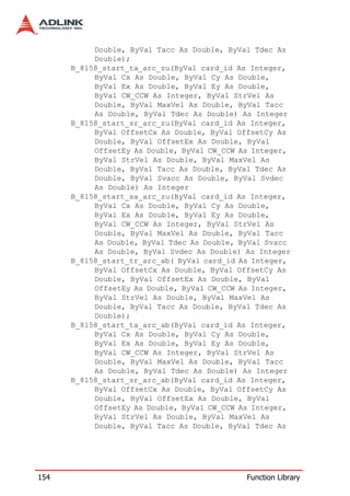
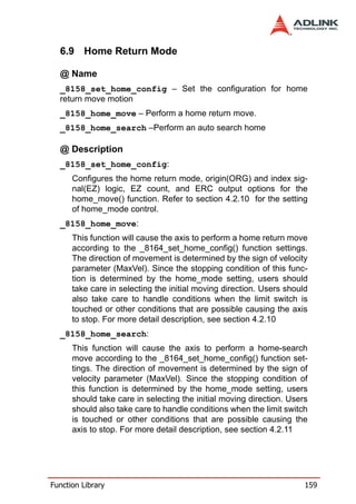
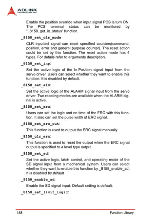
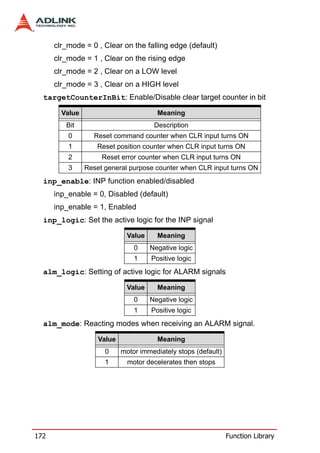
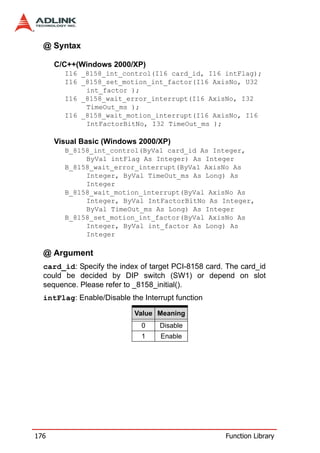
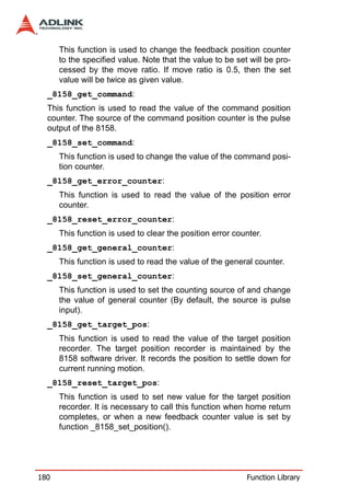
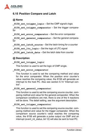
![*OffsetEnd: Array of the offset to end of arc (relative to the start
position)
Example: F64 OffsetEnd[2] = {4000.0, 0.0}; //offset from start
position(initial point for 1st & 2nd axes
*CenterPos: Array of the center of arc absolute position
Example: F64 CenterPos[2] = {2000.0, 0.0}; //absolute center
position for 1st & 2nd axes
*EndPos: Array of the end point of arc absolute position
Example: F64 EndPos[2] = {4000.0, 0.0}; //absolute end posi-
tion for 1st & 2nd axes
158 Function Library](https://image.slidesharecdn.com/pci-8158manual10-120311204859-phpapp01/85/Pci-8158-manual-10-168-320.jpg)
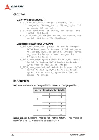
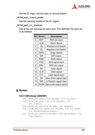
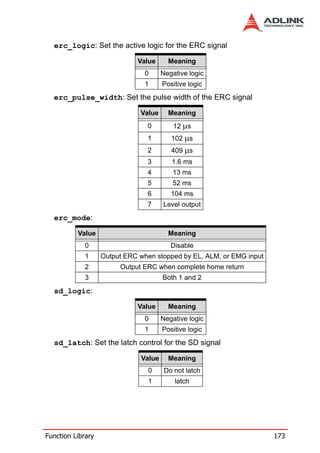
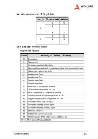
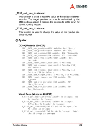
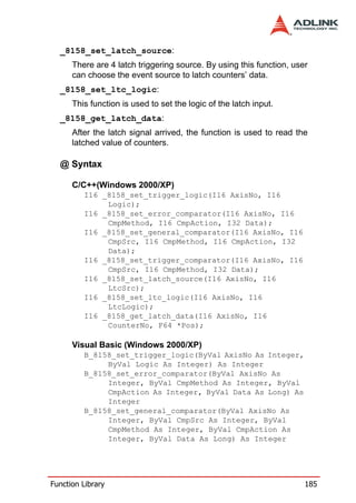
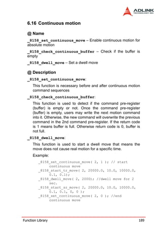
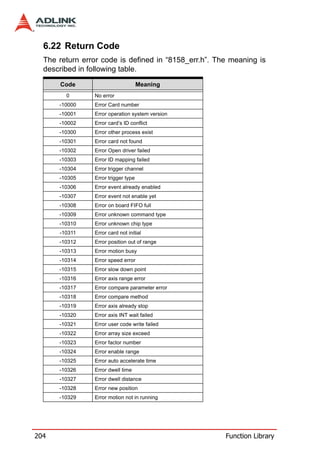
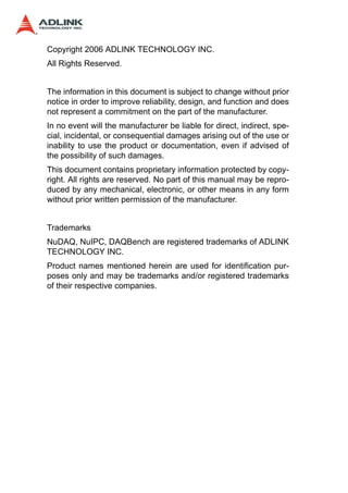
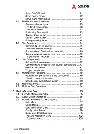
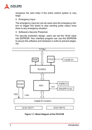
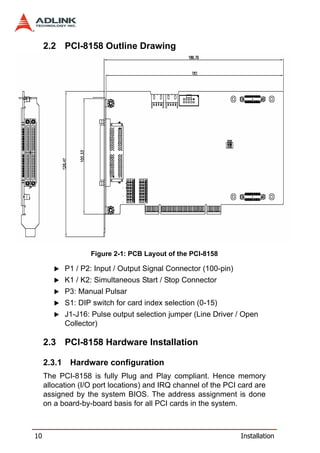
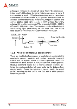
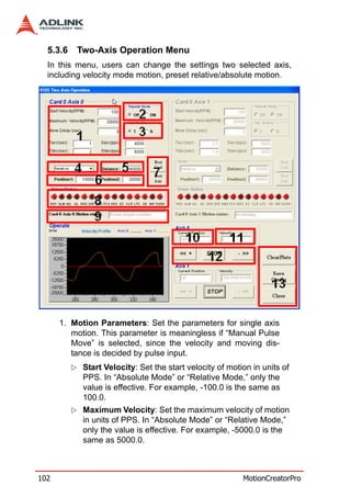
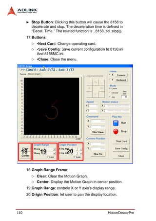
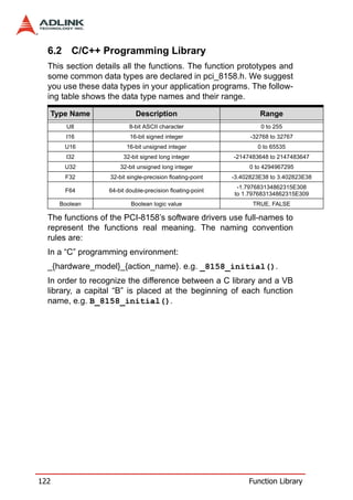
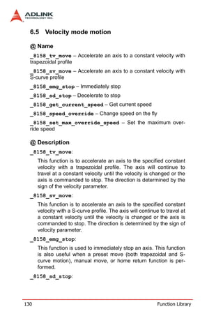
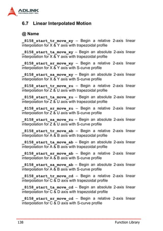
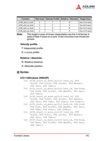
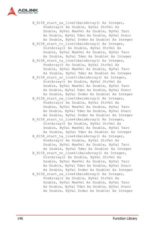
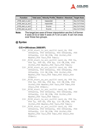
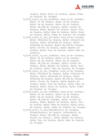
![6.17 Multiple Axes Simultaneous Operation
@ Name
_8158_set_tr_move_all – Multi-axis simultaneous operation
setup
_8158_set_ta_move_all – Multi-axis simultaneous operation
setup
_8158_set_sr_move_all – Multi-axis simultaneous operation
setup
_8158_set_sa_move_all – Multi-axis simultaneous operation
setup
_8158_start_move_all – Begin a multi-axis trapezoidal profile
motion
_8158_stop_move_all – Simultaneously stop Multi-axis motion
@ Description
Theses functions are related to simultaneous operations of multi-
axes, even in different cards. The simultaneous multi-axis opera-
tion means to start or stop moving specified axes at the same
time. The axes moved are specified by the parameter “AxisArray,”
and the number of axes are defined by parameter “TotalAxes” in
_8158_set_tr_move_all().
When properly setup with _8158_set_xx_move_all(), the function
_8158_start_move_all() will cause all specified axes to begin a
trapezoidal relative movement, and _8158_stop_move_all() will
stop them. Both functions guarantee that motion Starting/Stopping
on all specified axes are at the same time. Note that it is neces-
sary to make connections according to section 2.6 if these two
functions are needed.
The following code demos how to utilize these functions. This
code moves axis 0 and axis 1 to distance 80000.0 and 120000.0
respectively. If we choose velocities and accelerations that are
proportional to the ratio of distances, then the axes will arrive at
their endpoints at the same time.
[Example]
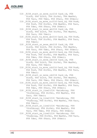
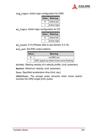
Function Library 191](https://image.slidesharecdn.com/pci-8158manual10-120311204859-phpapp01/85/Pci-8158-manual-10-201-320.jpg)
![I16 axes[2] = {0, 1};
F64 dist[2] = {80000.0, 120000.0},
F64 str_vel[2] = {0.0, 0.0},
F64 max_vel[2] = {4000.0, 6000.0},
F64 Tacc[2] = {0.1, 0.6},
F64 Tdec[2] = {0.1, 0.6};
_8158_set_tr_move_all(2, axes, dist, str_vel,
max_vel, Tacc, Tdec);
_8158_start_move_all(axes[0]);
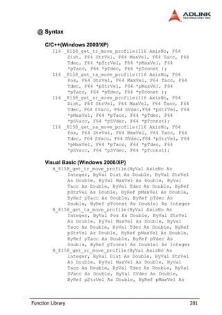
@ Syntax
C/C++(Windows 2000/XP)
I16 _8158_set_tr_move_all(I16 TotalAxes, I16
*AxisArray, F64 *DistA, F64 *StrVelA, F64
*MaxVelA, F64 *TaccA, F64 *TdecA);
I16 _8158_set_ta_move_all(I16 TotalAx, I16
*AxisArray, F64 *PosA, F64 *StrVelA, F64
*MaxVelA, F64 *TaccA, F64 *TdecA);
I16 _8158_set_sr_move_all(I16 TotalAx, I16
*AxisArray, F64 *DistA, F64 *StrVelA, F64
*MaxVelA, F64 *TaccA, F64 *TdecA, F64
*SVaccA, F64 *SVdecA);
I16 _8158_set_sa_move_all(I16 TotalAx, I16
*AxisArray, F64 *PosA, F64 *StrVelA, F64
*MaxVelA, F64 *TaccA, F64 *TdecA, F64
*SVaccA, F64 *SVdecA);
I16 _8158_start_move_all(I16 FirstAxisNo);
I16 _8158_stop_move_all(I16 FirstAxisNo);
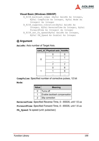
Visual Basic (Windows 2000/XP)
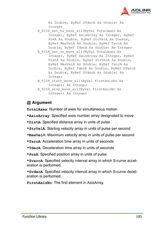
B_8158_set_tr_move_all(ByVal TotalAxes As
Integer, ByRef AxisArray As Integer, ByRef
DistA As Double, ByRef StrVelA As Double,
ByRef MaxVelA As Double, ByRef TaccA As
Double, ByRef TdecA As Double) As Integer
B_8158_set_sa_move_all(ByVal TotalAxes As
Integer, ByRef AxisArray As Integer, ByRef
PosA As Double, ByRef StrVelA As Double,
ByRef MaxVelA As Double, ByRef TaccA As
Double, ByRef TdecA As Double, ByRef SVaccA
192 Function Library](https://image.slidesharecdn.com/pci-8158manual10-120311204859-phpapp01/85/Pci-8158-manual-10-202-320.jpg)