Download to read offline


![en | 32 | User guide | CP9690 Elite AutoScanner®
573464 | REV. B | 03.2016 Bosch Automotive Service Solutions Inc.
MIL is OFF
Press ENTER to continue
MIL lamp should be OFF
engine is running
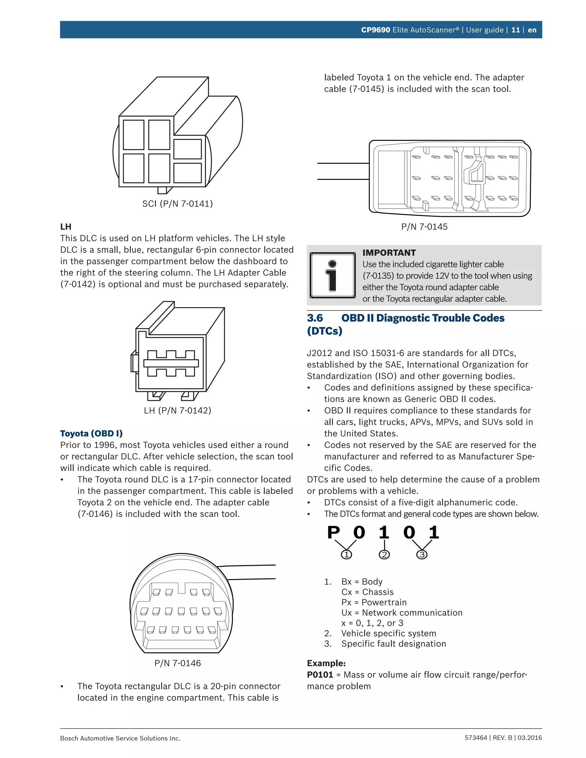
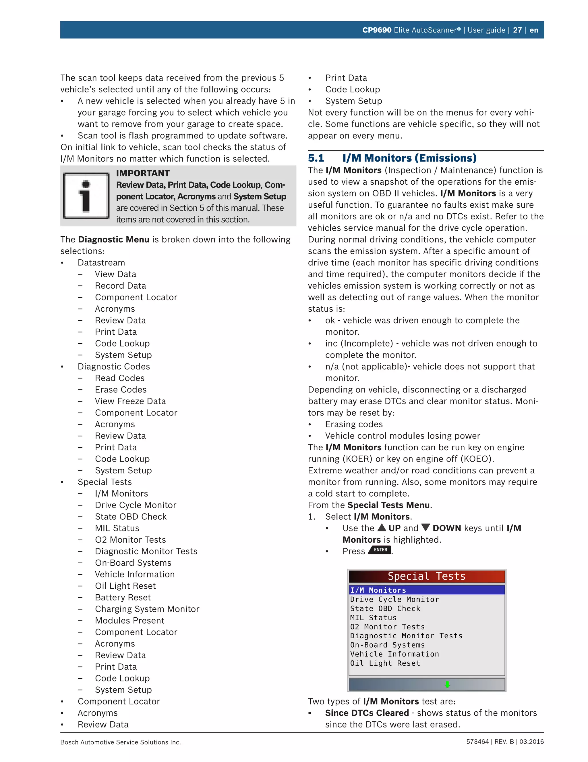
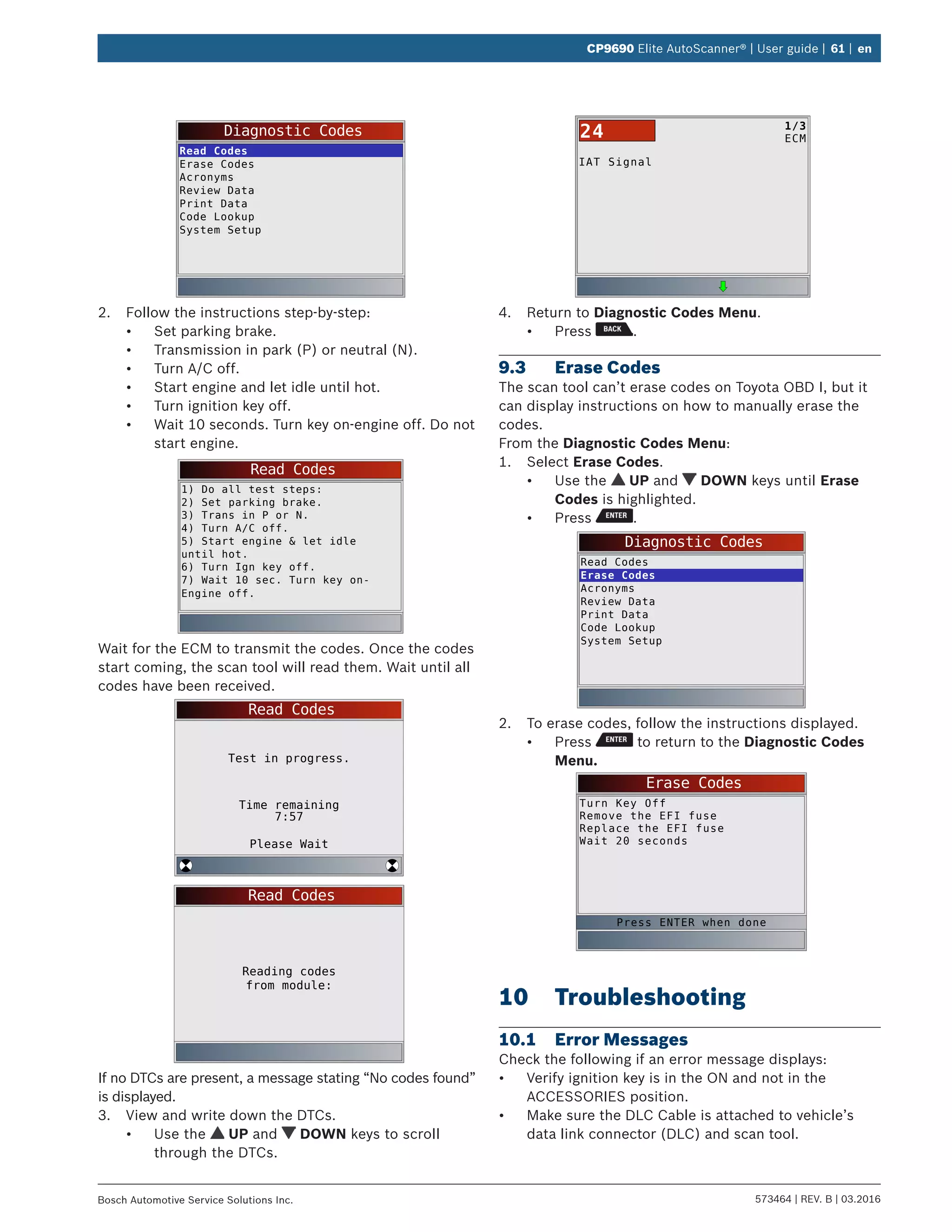
5.5 State OBD Check
The State OBD Check function is used to display a basic
status of the vehicles OBD system.
• Malfunction indicator lamp (MIL) status
• Codes found
• I/M monitors
Erase Codes deletes DTCs and resets I/M monitors from
vehicle’s computer module(s).
The State OBD Check function has the following areas:
• MIL Status ON or OFF
• Number of Codes Found
• Number of Monitors OK
• Number of Monitors Inc
• Number of Monitors N/A
State OBD Check should be done with the key on
engine running (KOER) due to showing MIL status.
The number of codes found are only Global OBD II codes and
not pending codes.
The number of monitors that are either ok, inc, or na are
only Since DTCs Cleared and not This Drive Cycle.
Refer to”5.1 I/M Monitors (Emissions)” on page
27 and “5.2 Read Codes” on page 28 for more
detailed information about the results.
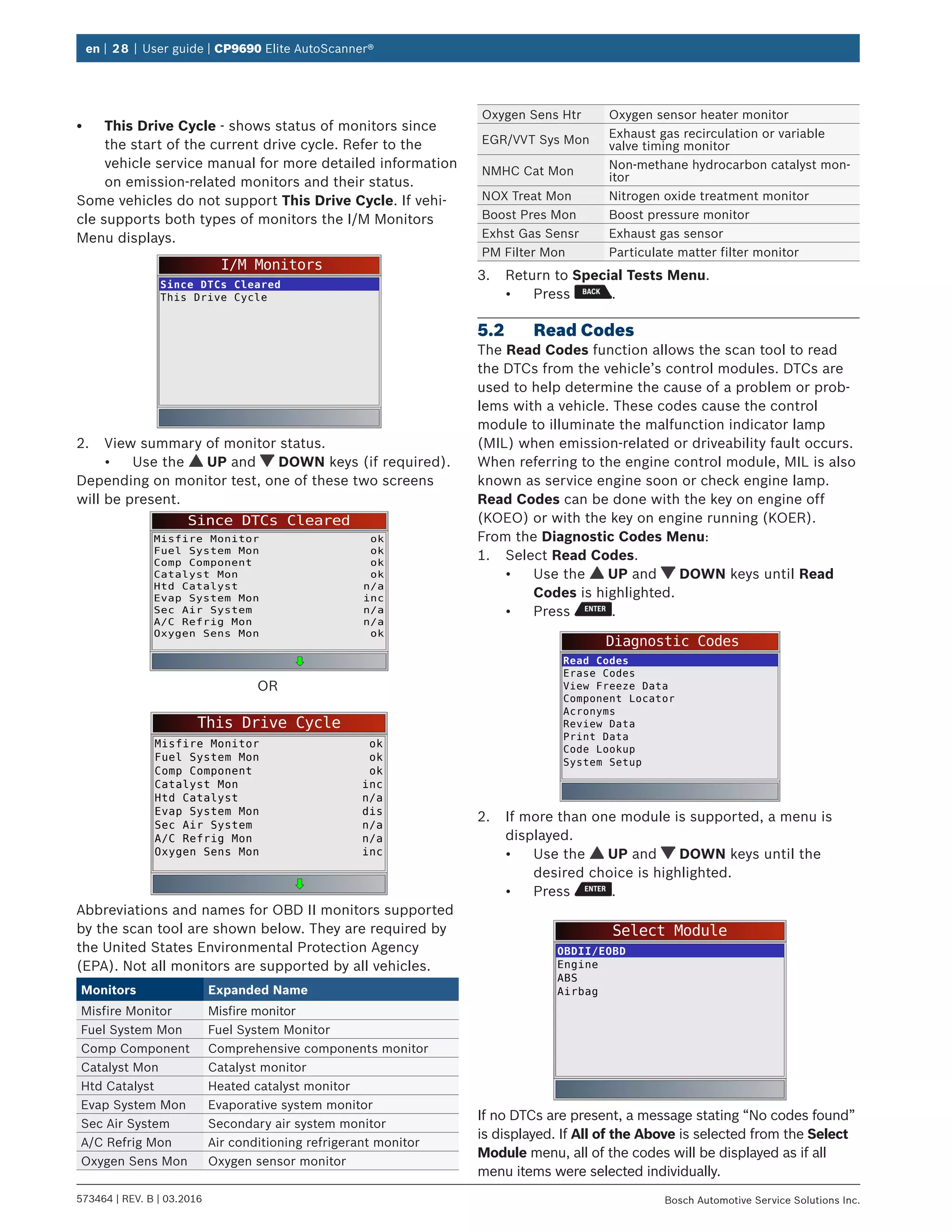
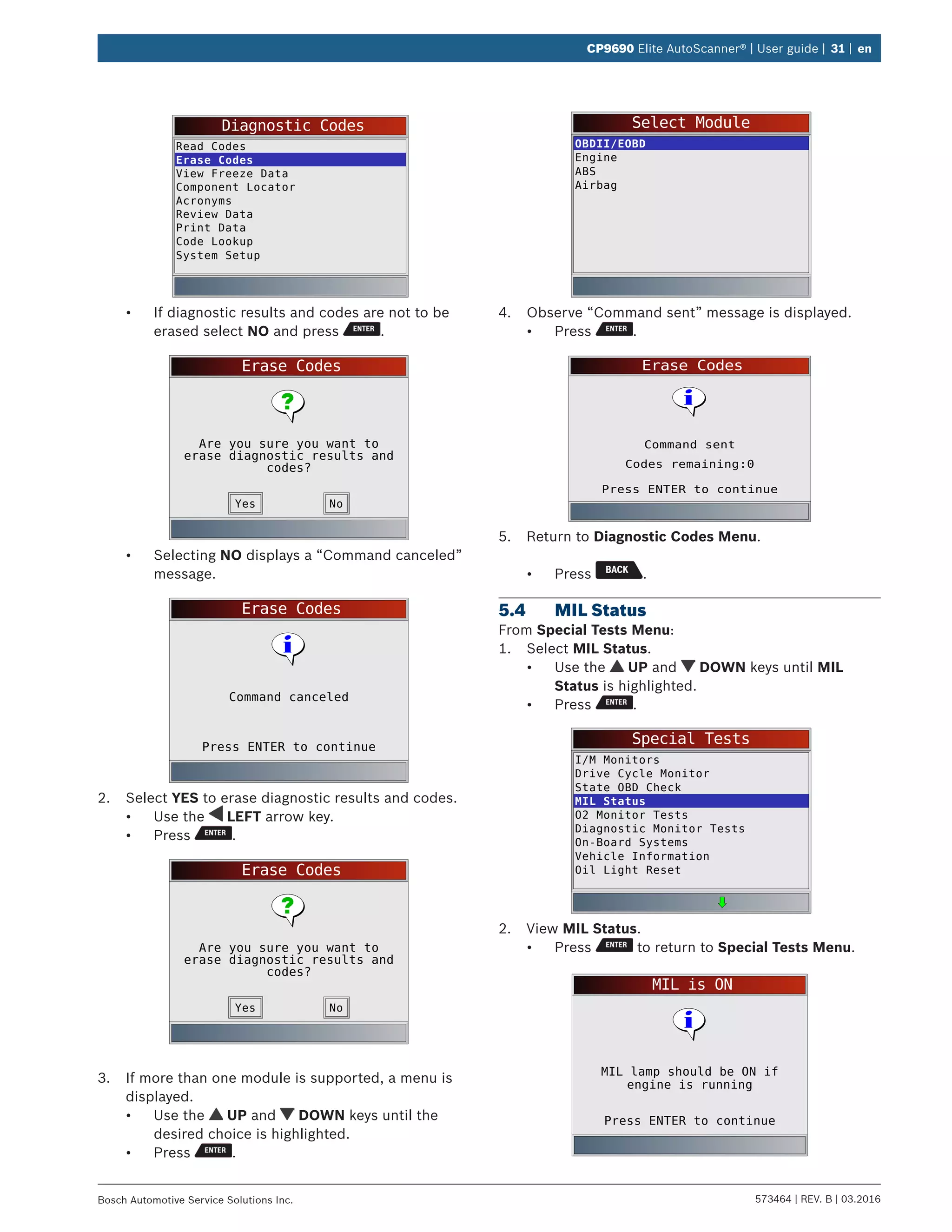
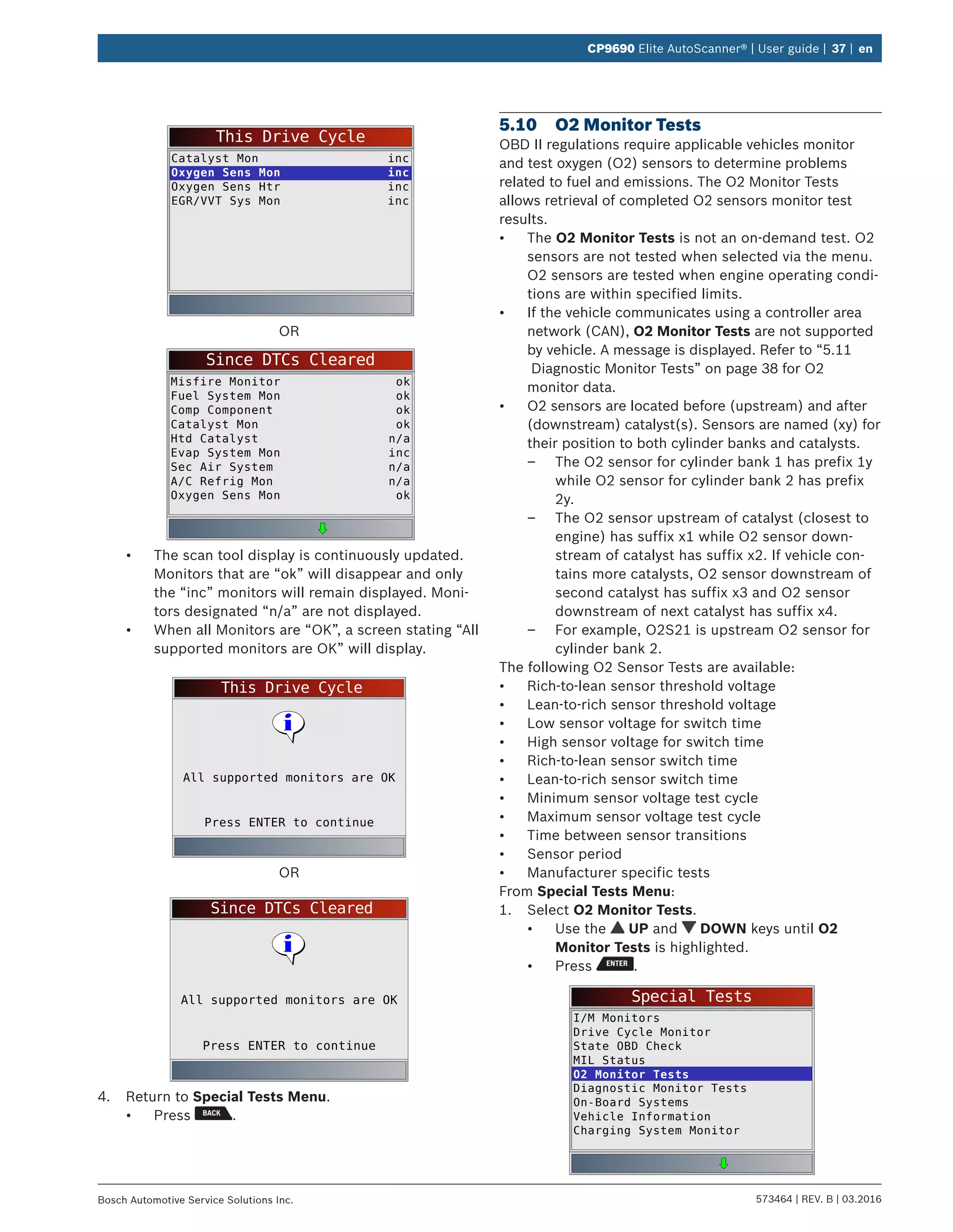
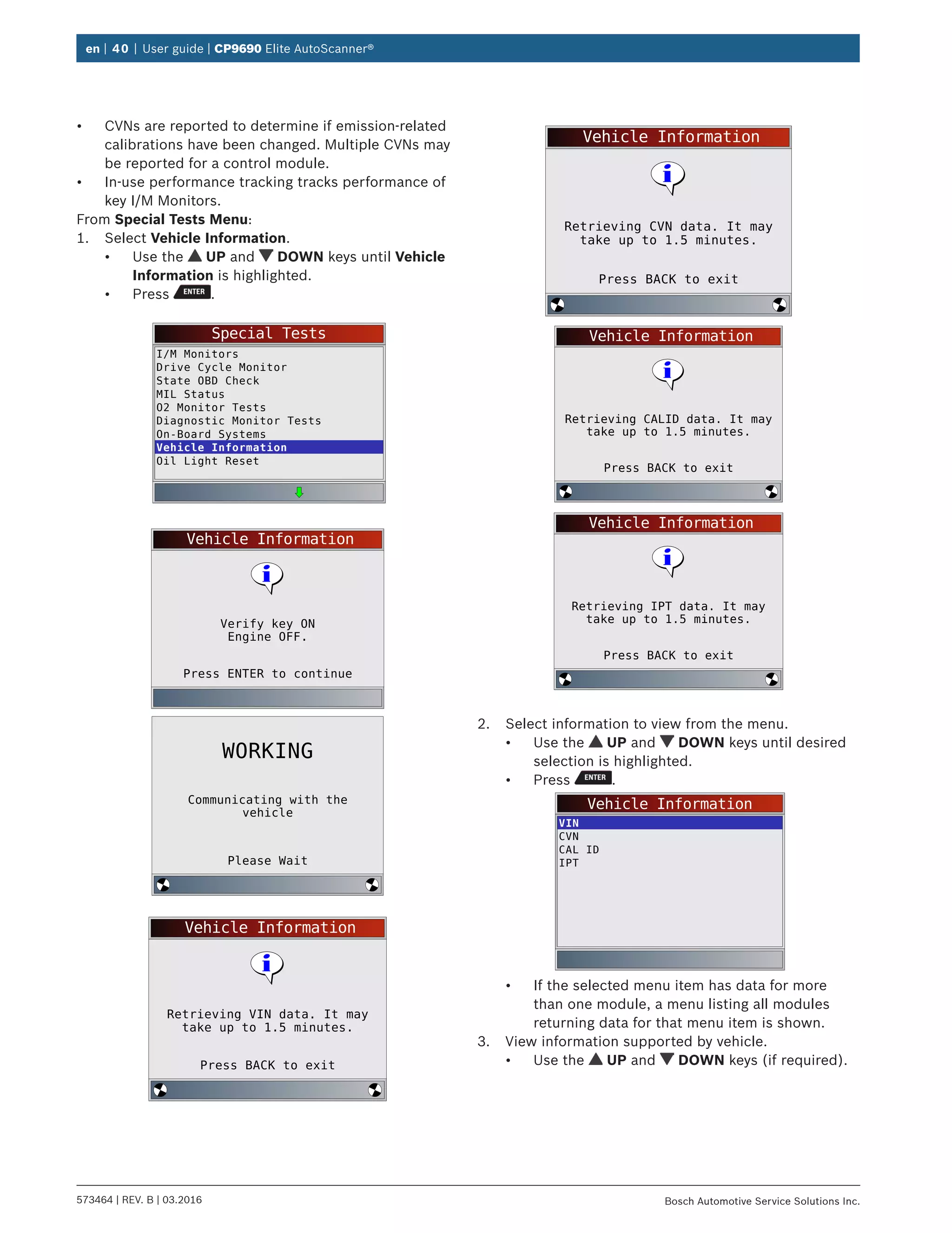
From Special Tests Menu:
1. Select State OBD Check.
• Use the UP and DOWN keys until State
OBD Check is highlighted.
• Press .
Special Tests
I/M Monitors
Drive Cycle Monitor
State OBD Check
MIL Status
O2 Monitor Tests
Diagnostic Monitor Tests
On-Board Systems
Vehicle Information
Oil Light Reset
2. View State OBD Check display.
State OBD Check
MIL Status
Codes Found
Monitors OK
Monitors Inc
Monitors N/A
OFF
0
3
4
4
3. Return to Special Tests Menu.
• Press .
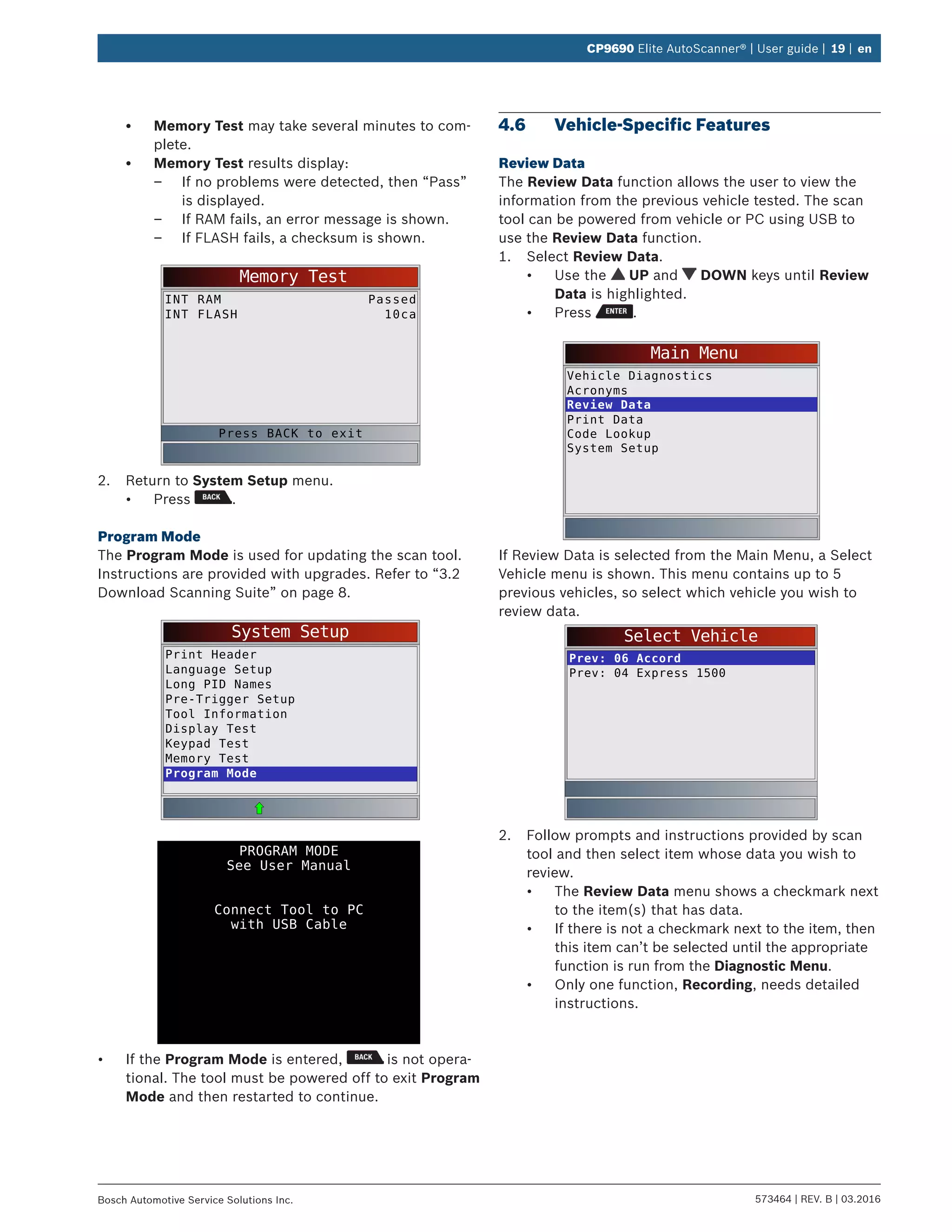
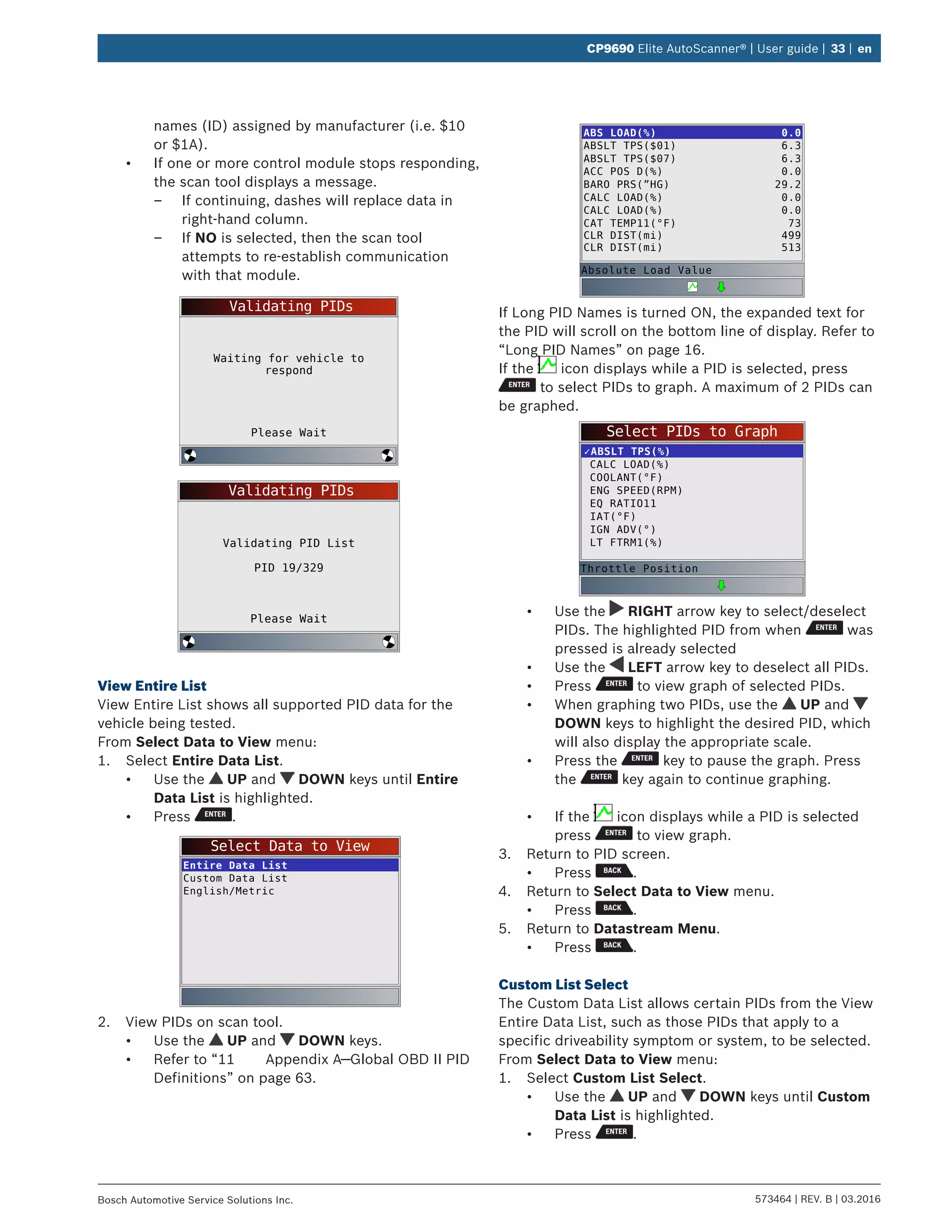
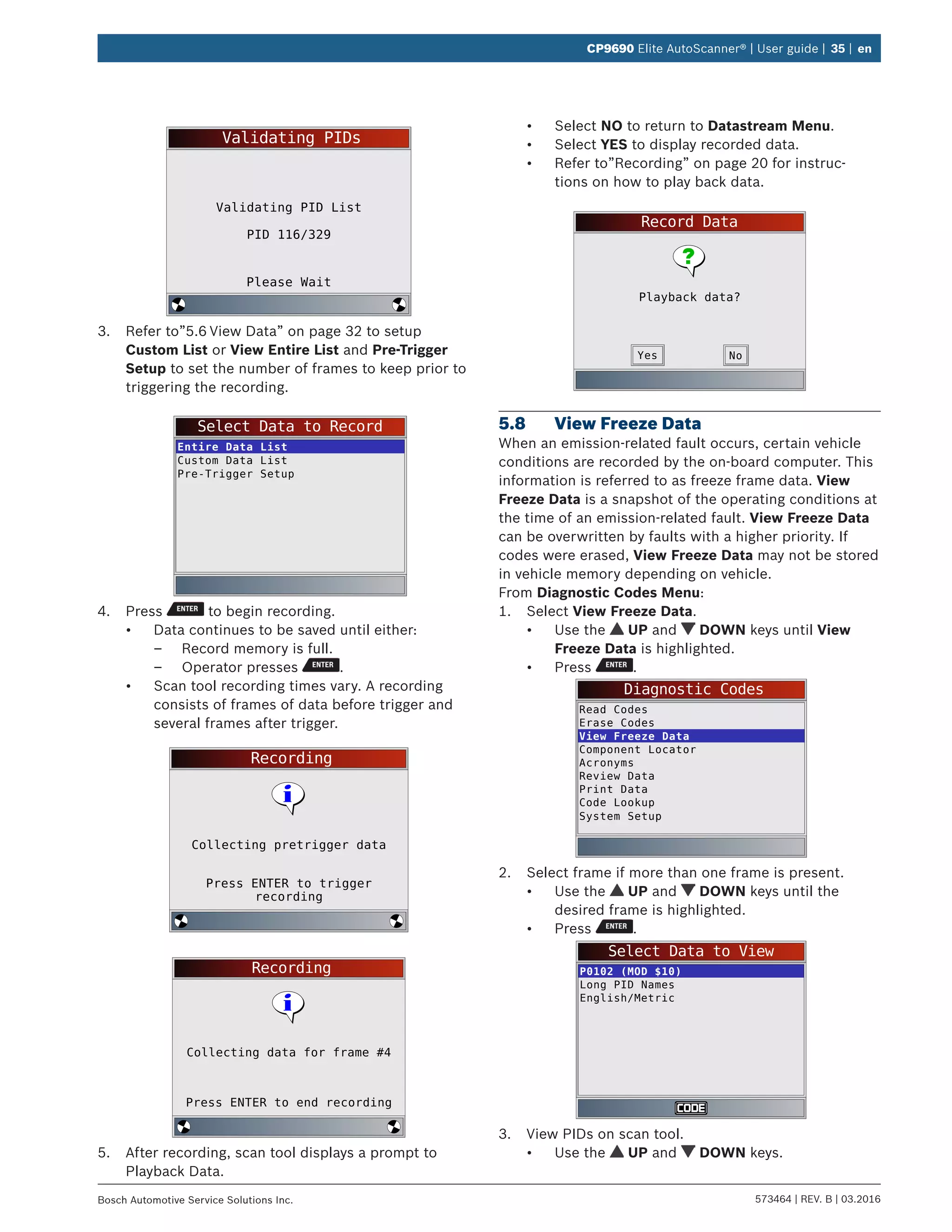
5.6 View Data
The View Data function allows real time viewing of the
vehicle’s computer module’s parameter identification
(PID) data. As the computer monitors the vehicle, infor-
mation is simultaneously transmitted to scan tool.
View Data allows the following items to be viewed on
the scan tool:
• Sensor data
• Operation of switches
• Operation of solenoids
• Operation of relays
View Data can be shown as:
• Entire Data List
• Custom Data List
Apart from Read Codes, View Data is the most useful
diagnostic function for isolating the cause of a vehicle
operation problem.
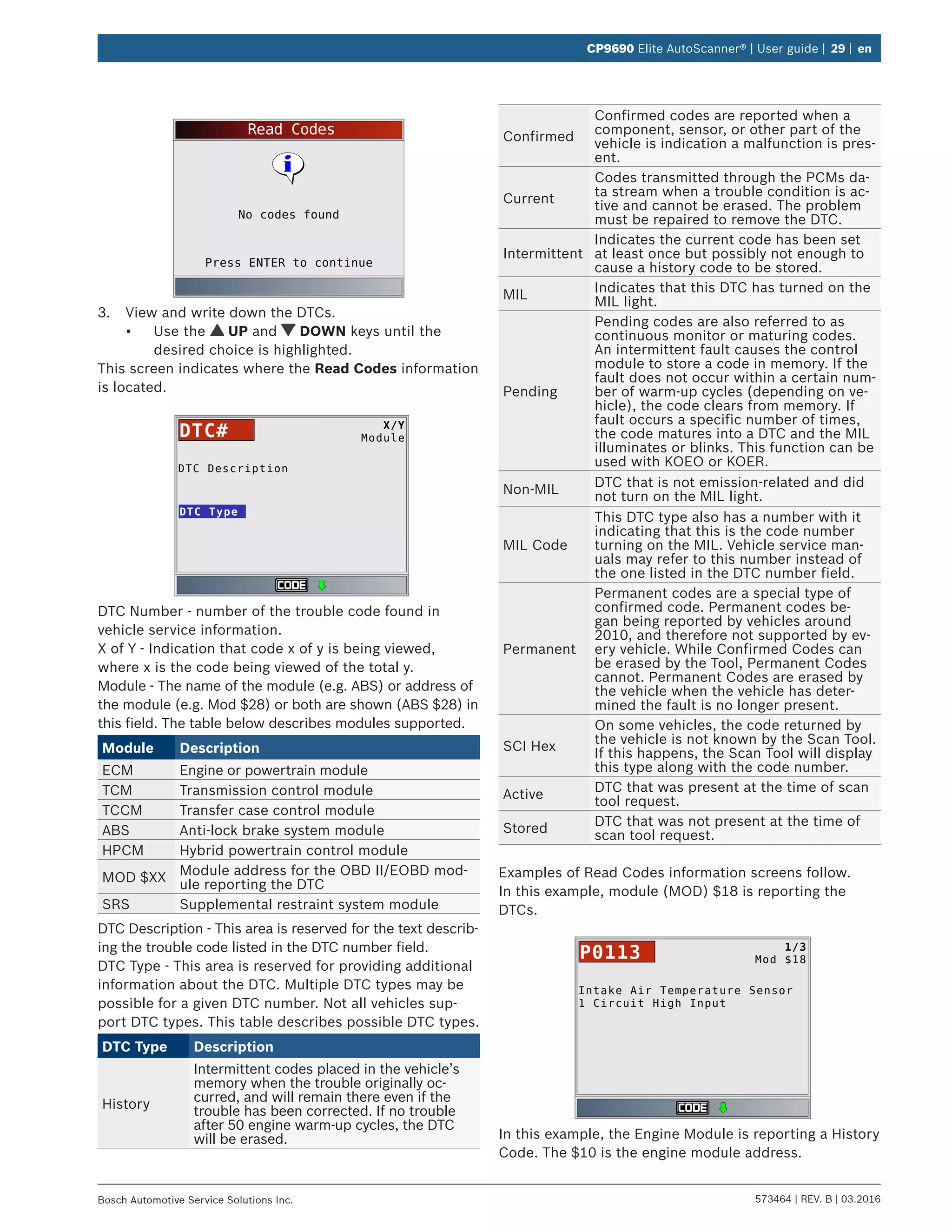
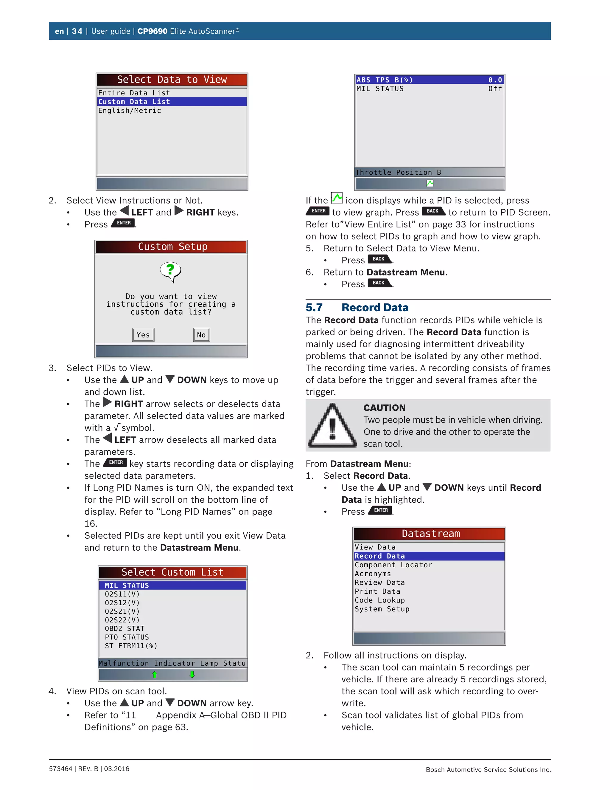
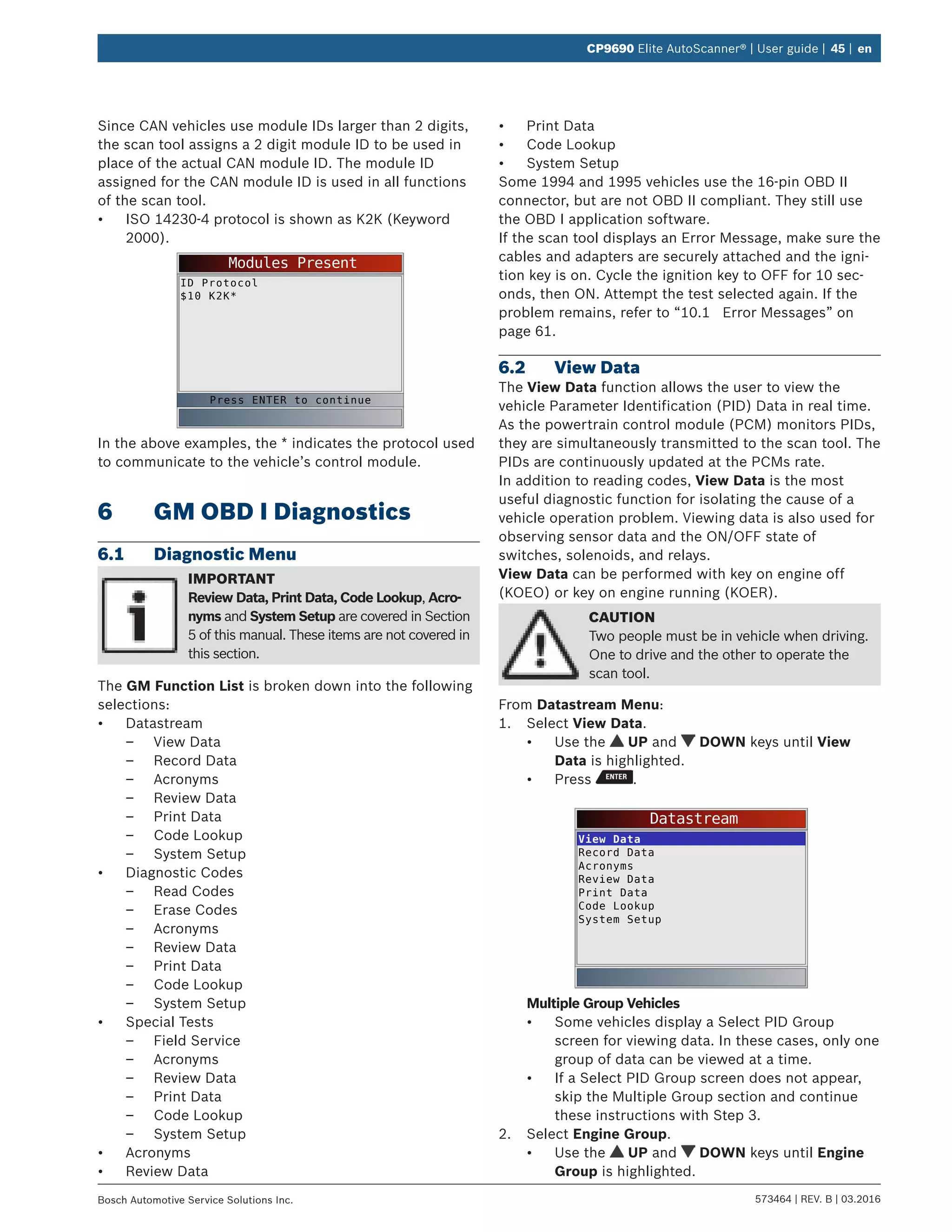
From Datastream Menu:
1. Select View Data.
• Use the UP and DOWN keys until View
Data is highlighted.
• Press .
Datastream
View Data
Record Data
Component Locator
Acronyms
Review Data
Print Data
Code Lookup
System Setup
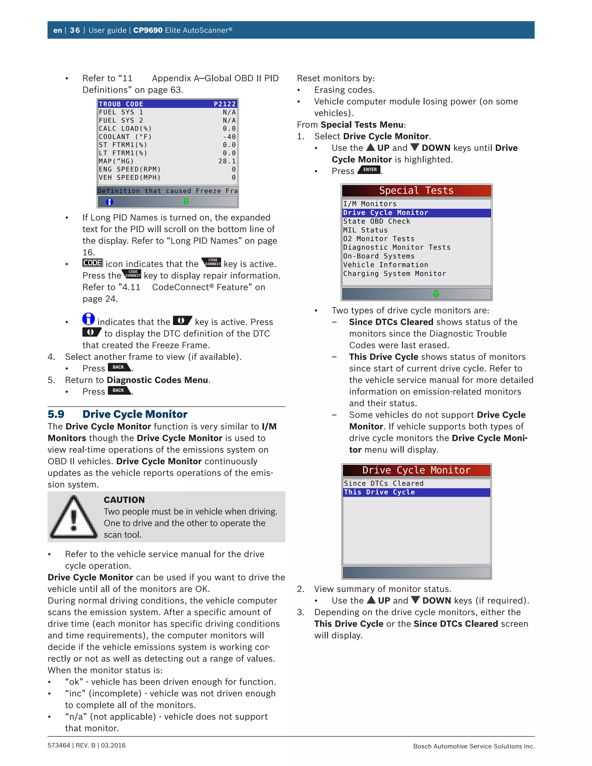
2. Observe while the scan tool validates PID MAP.
• PID MAP validation is the tool asking the vehicle
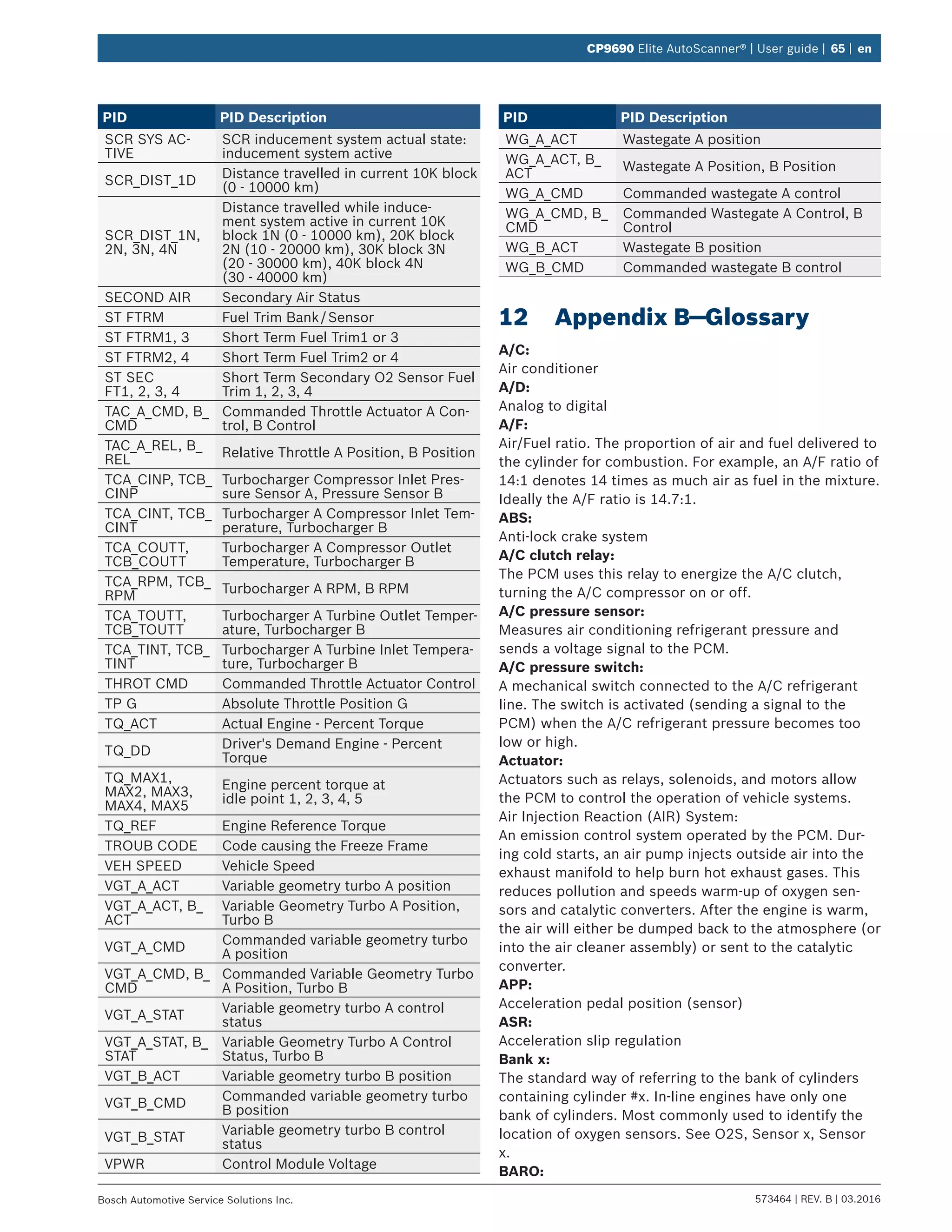
which PIDs are supported. Refer to “11
Appendix A—Global OBD II PID Definitions” on
page 63 for a complete list of PIDs supported
by the tool.
• Multiple PIDs may be sent if vehicle is equipped
with more than one computer module (for
example a powertrain control module [PCM]
and a transmission control module [TCM]). The
scan tool identifies them by their identification](https://image.slidesharecdn.com/actroncp9690-190116161154/75/Actron-CP9690-User-Manual-32-2048.jpg)

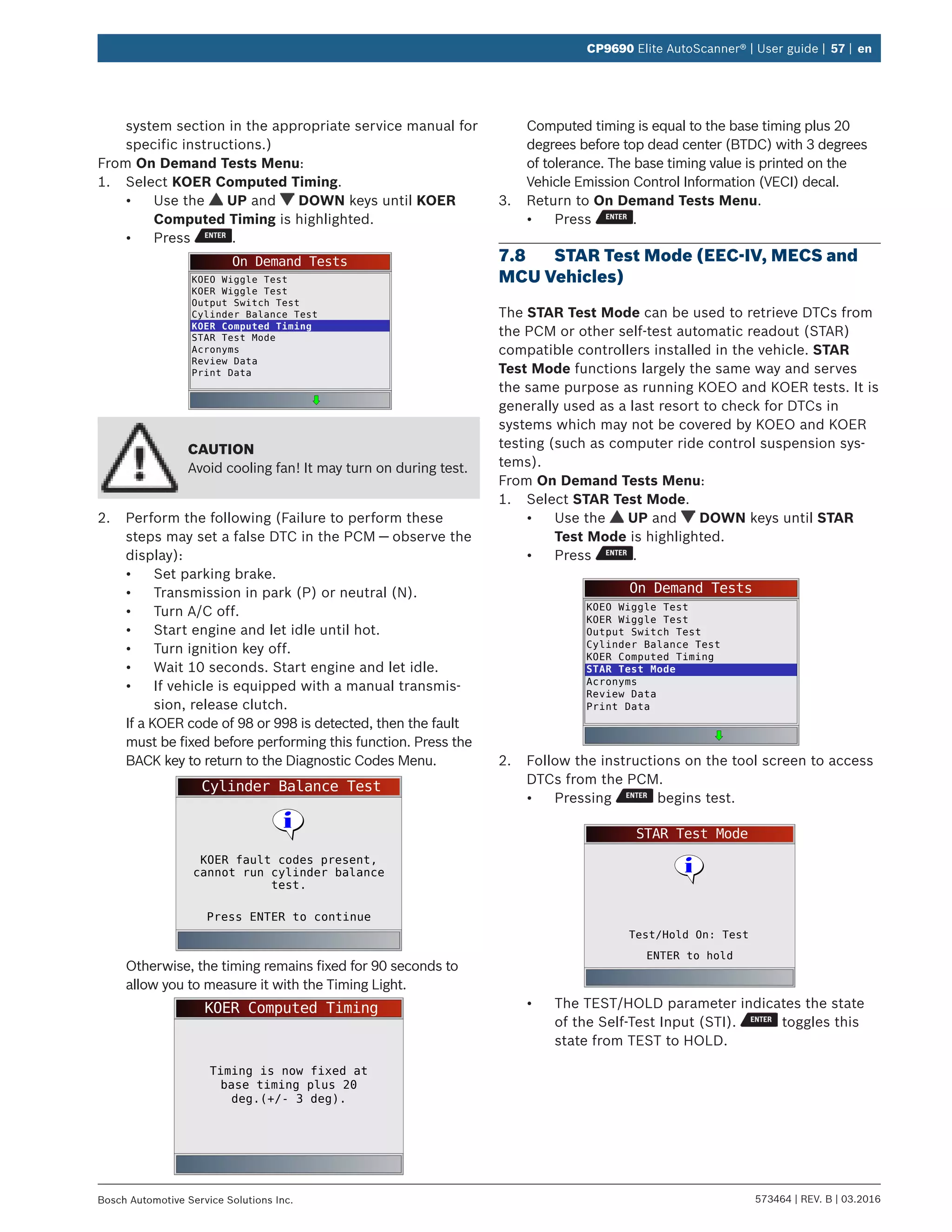


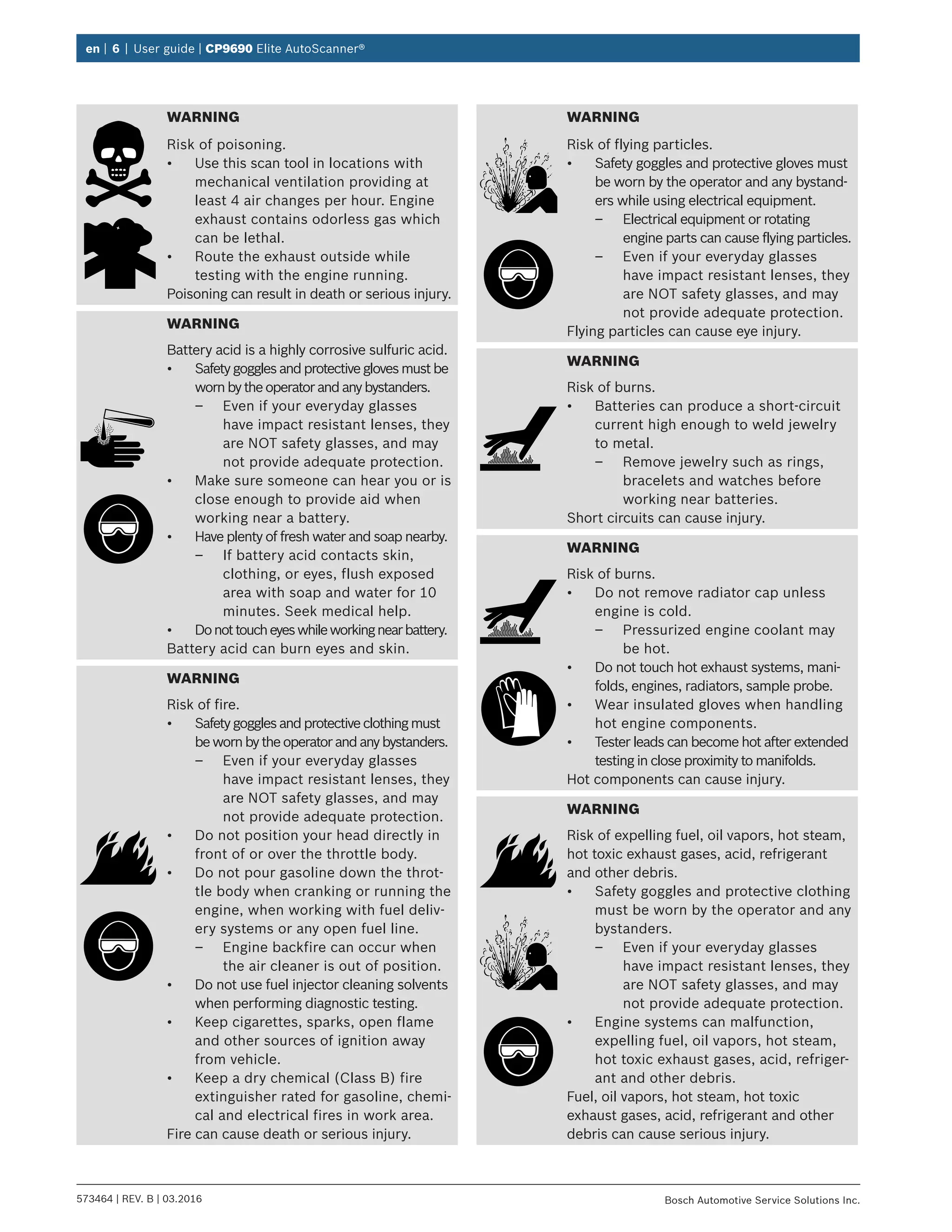
The document is the user guide for the CP9690 Elite Autoscanner, providing essential information on the tool's features, safety precautions, and troubleshooting. It includes details about on-board diagnostics (OBD I and OBD II), operating instructions, and specifications. Users can also find contact information for technical support and details on using various diagnostic functions.


![Mazda Dashboard Warning Lights: Symbols and Meanings [FULL LIST]](https://cdn.slidesharecdn.com/ss_thumbnails/mazda-warning-lights-221021085358-dcf733ba-thumbnail.jpg?width=640&height=640&fit=bounds)
![Mini Cooper Dashboard Warning Lights: Symbols and Meanings [FULL LIST]](https://cdn.slidesharecdn.com/ss_thumbnails/mini-cooper-warning-lights-221021084944-27b65ebd-thumbnail.jpg?width=640&height=640&fit=bounds)


![Toyota Dashboard Warning Lights [FULL]](https://cdn.slidesharecdn.com/ss_thumbnails/toyota-warning-lights-211126044903-thumbnail.jpg?width=640&height=640&fit=bounds)


![BMW Dashboard Warning Lights [FULL]](https://cdn.slidesharecdn.com/ss_thumbnails/bmwdashboardlights-211008082506-thumbnail.jpg?width=640&height=640&fit=bounds)


