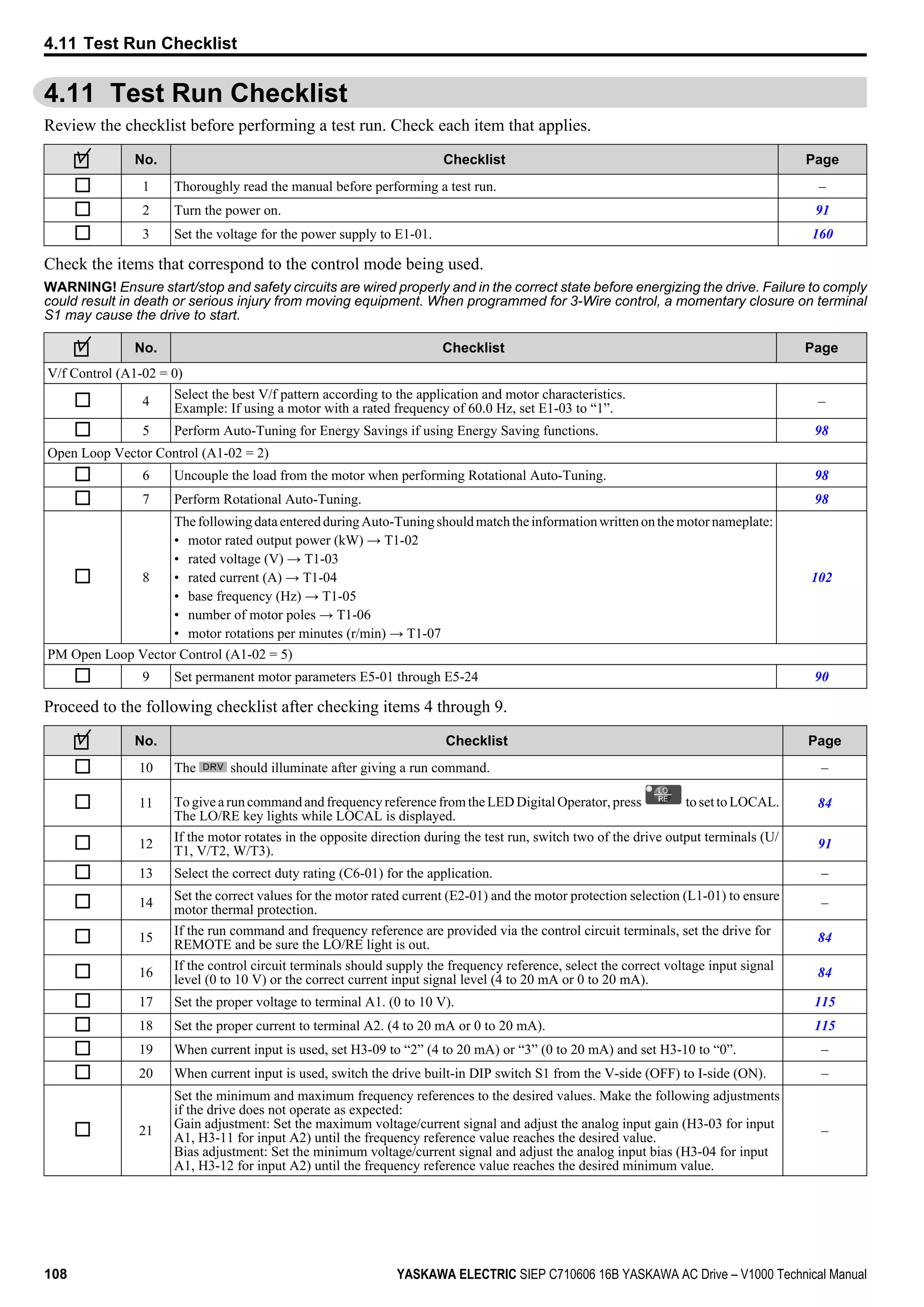
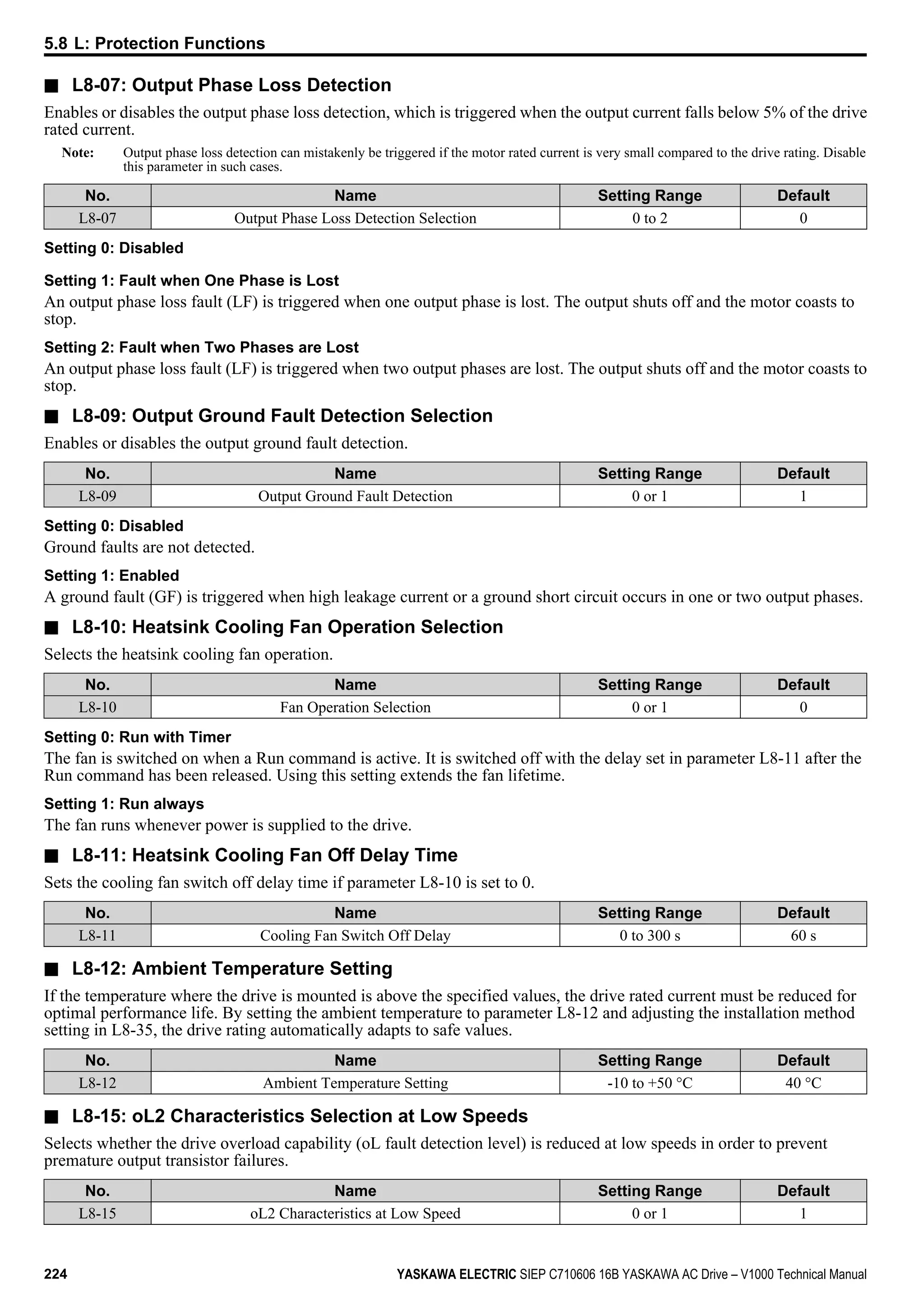
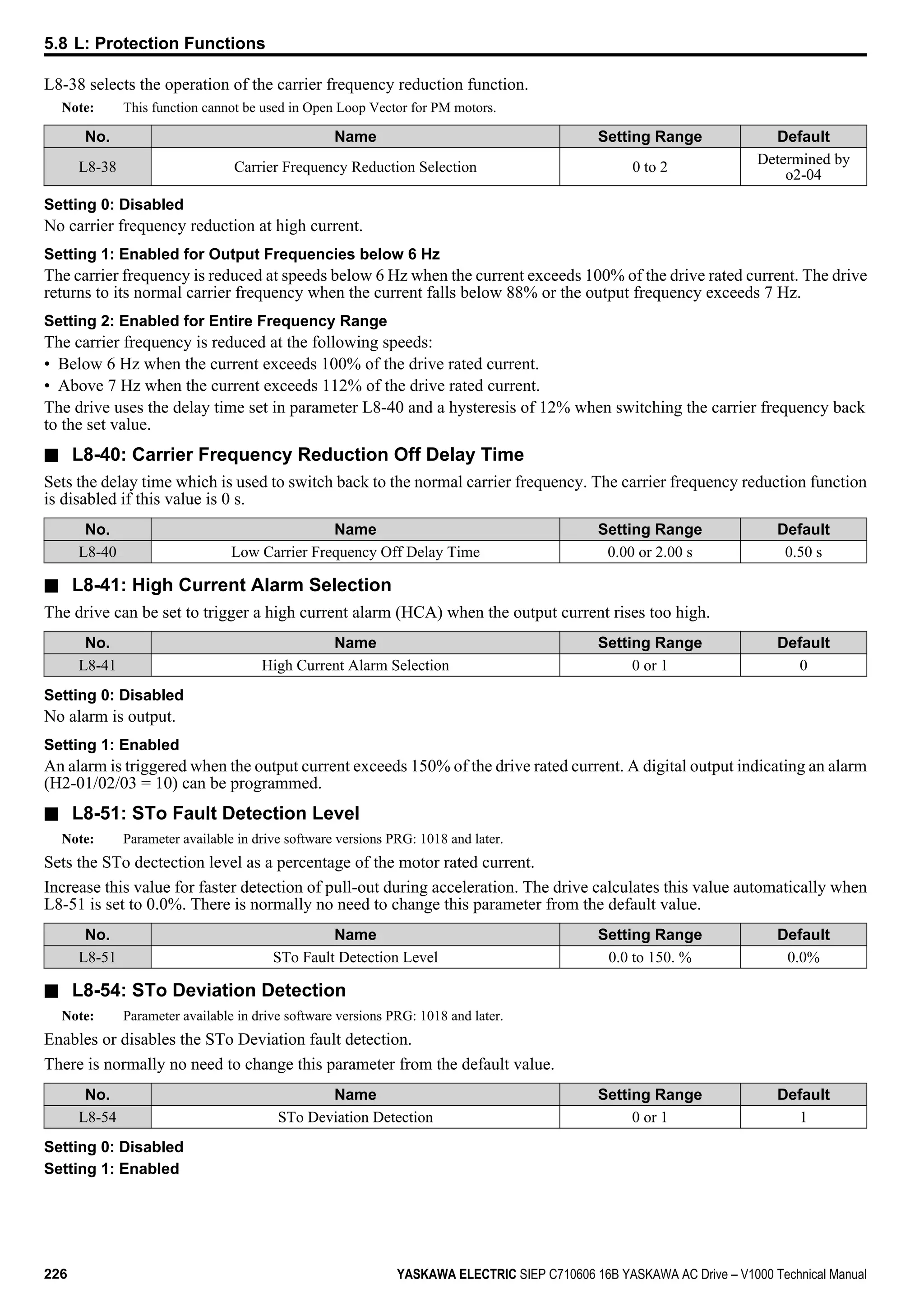
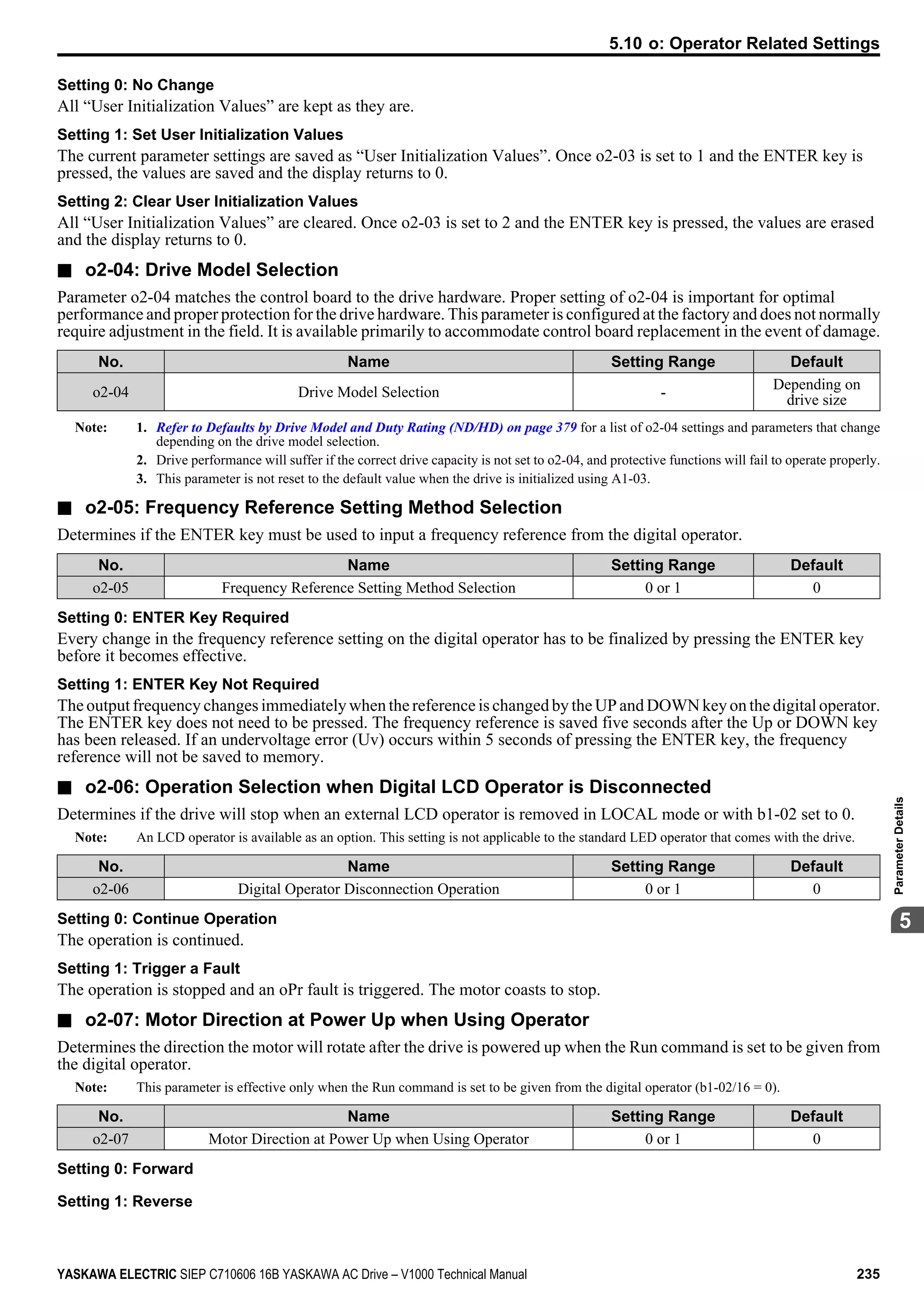
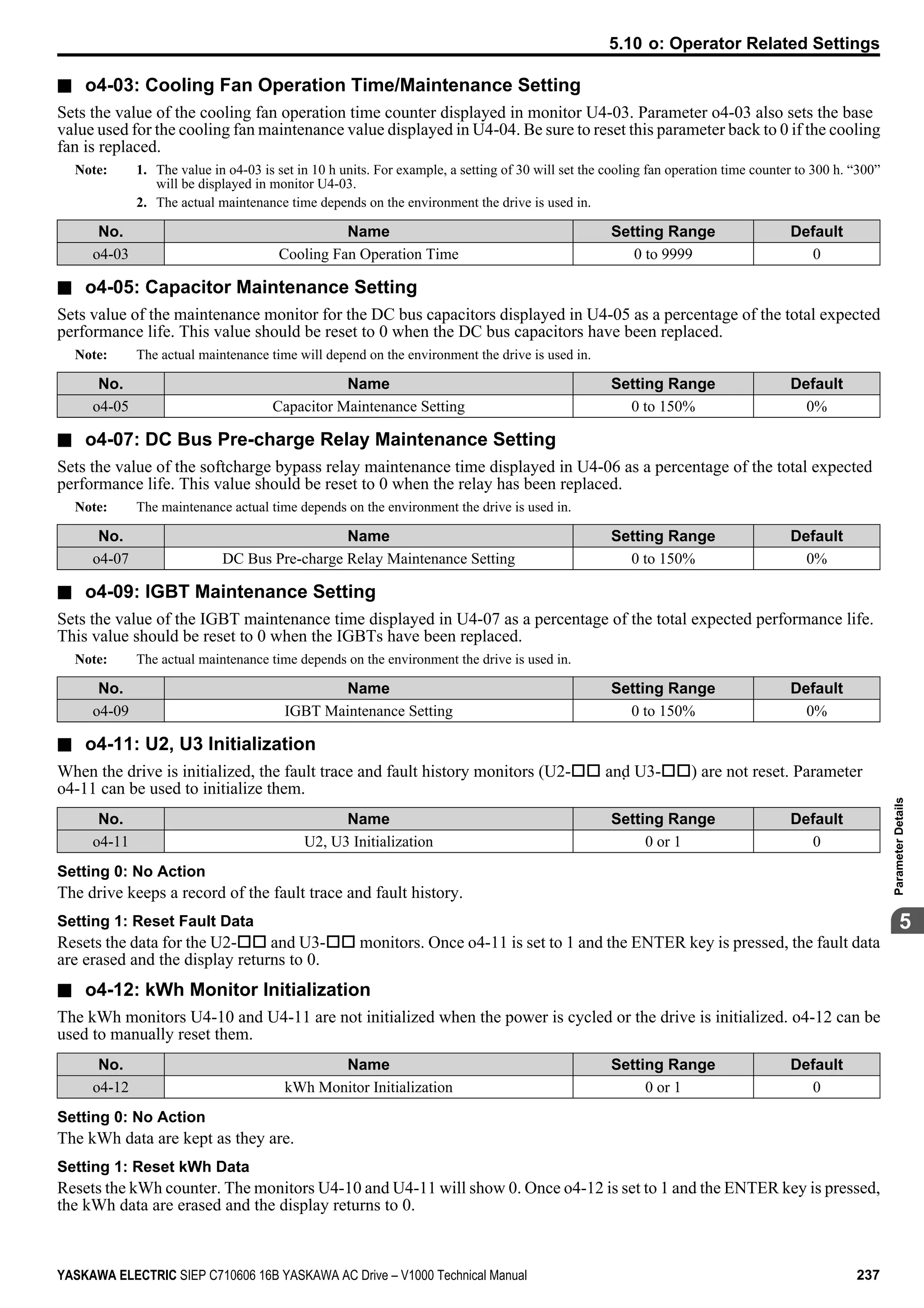
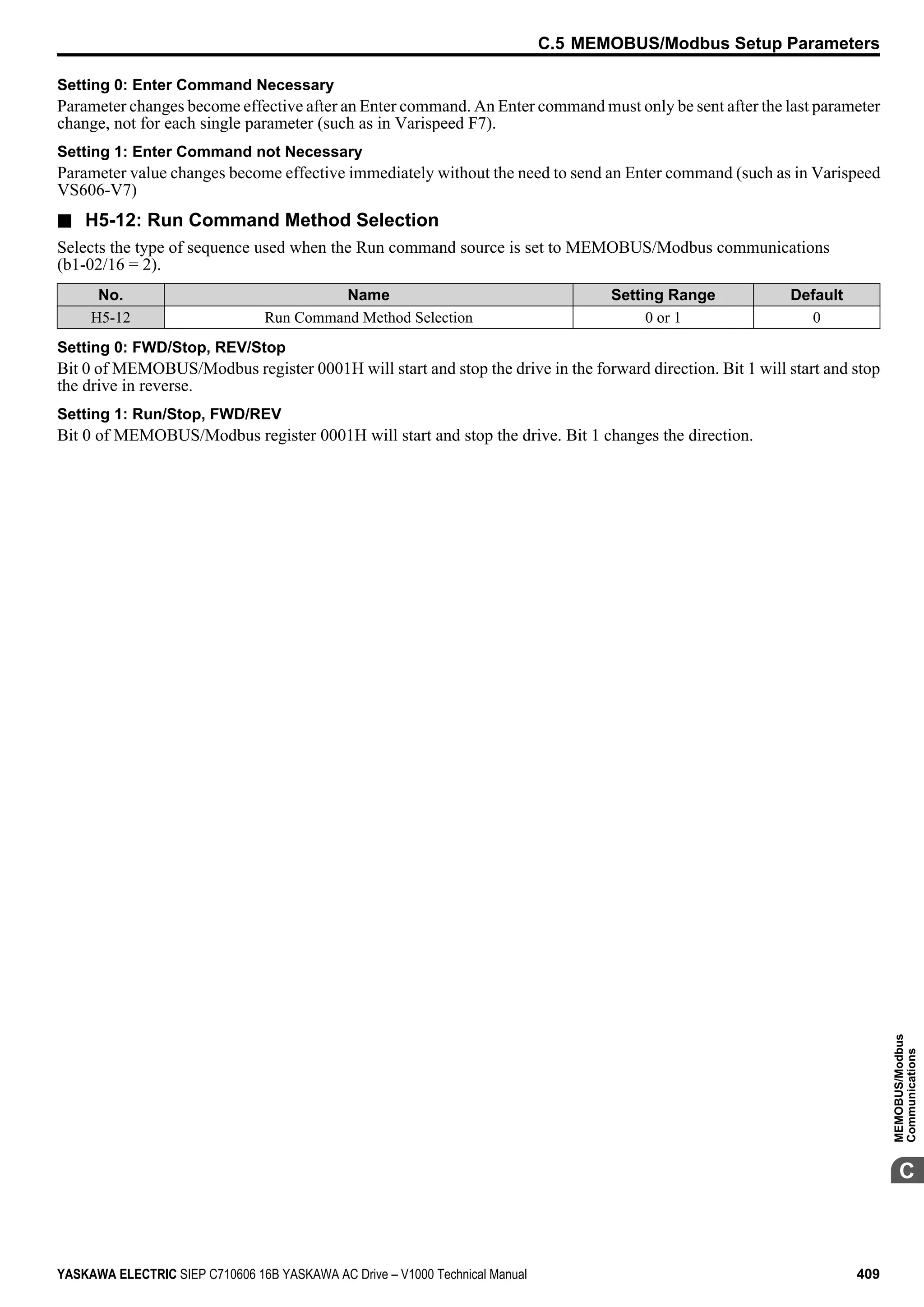
Download to read offline


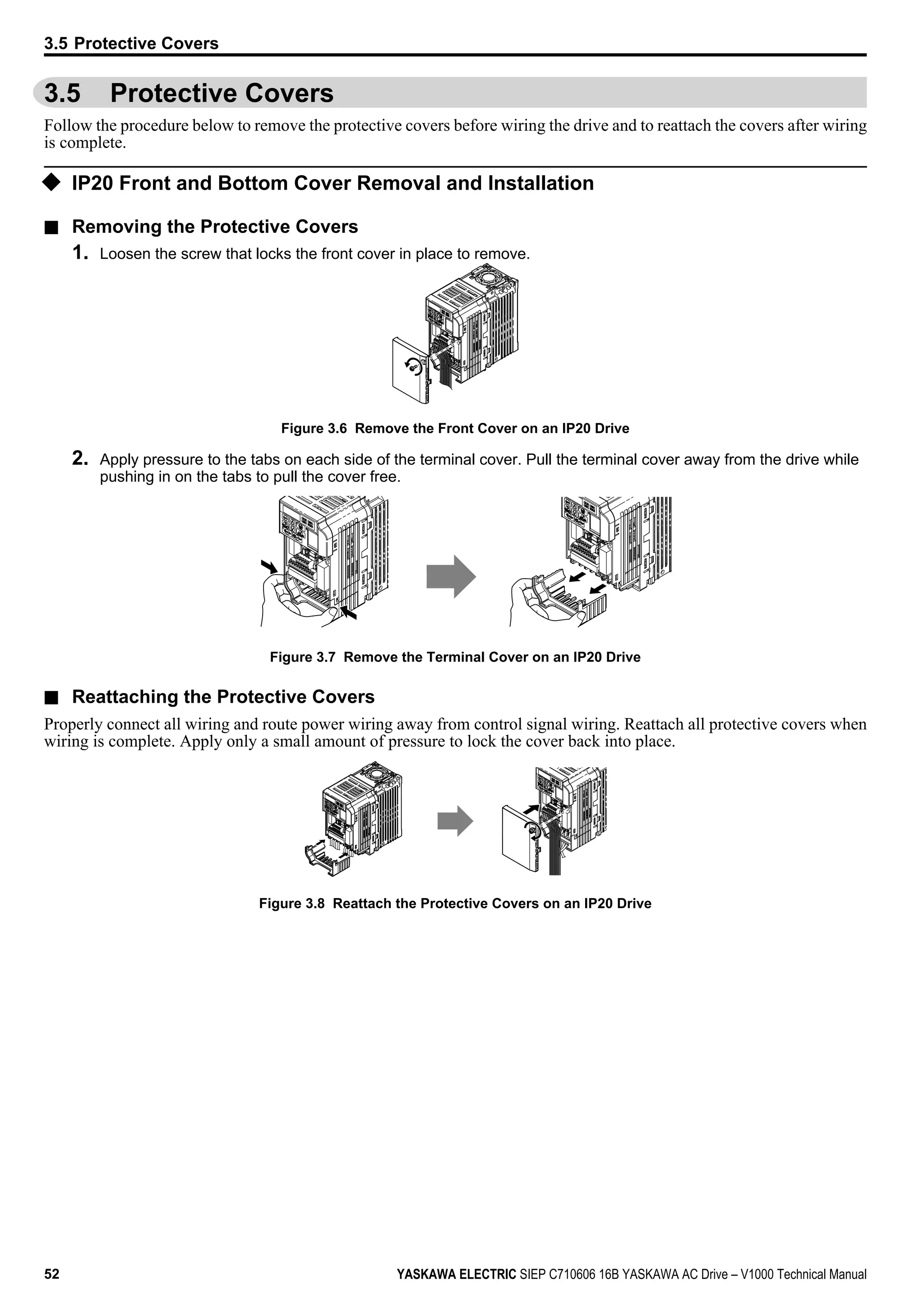


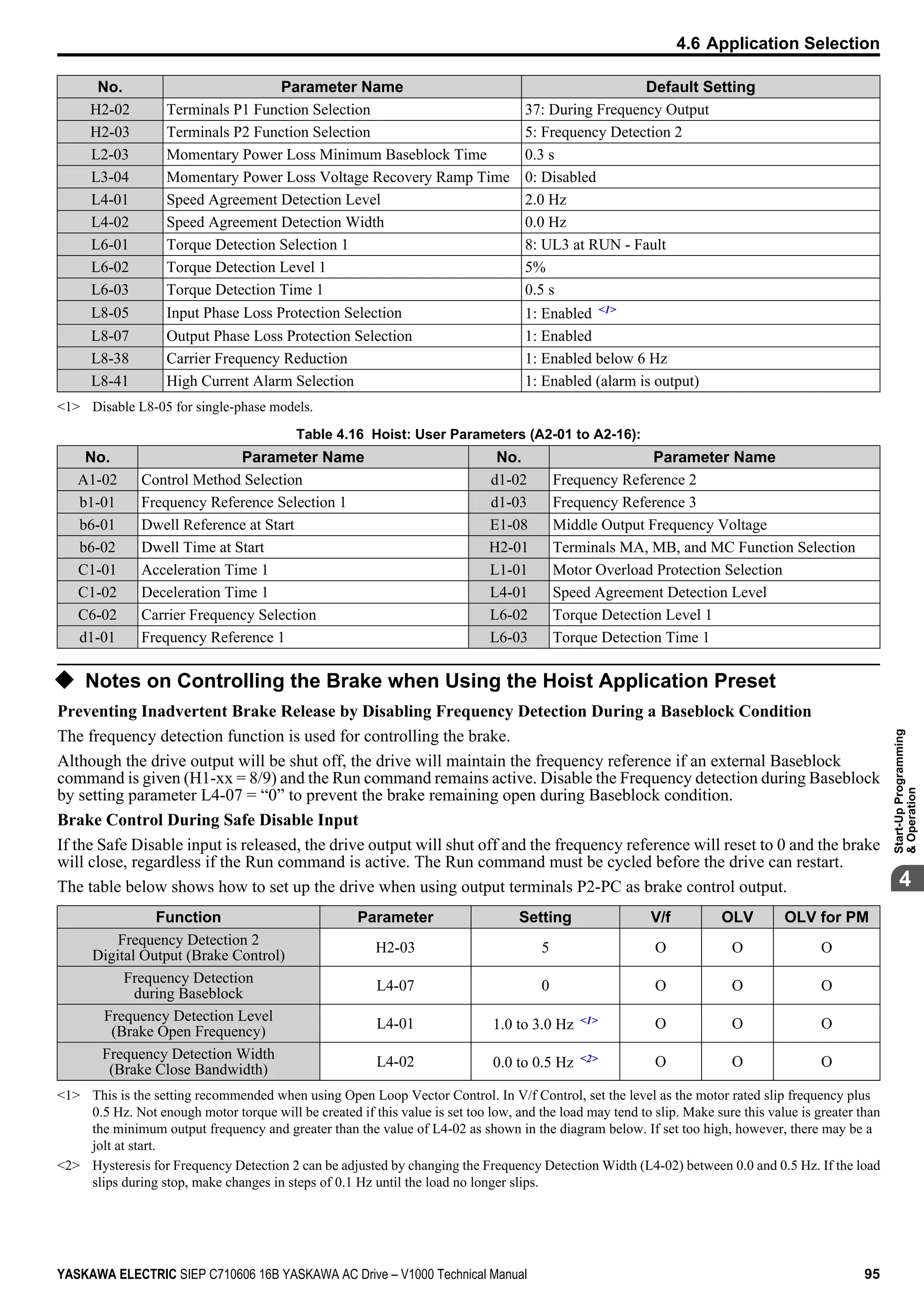


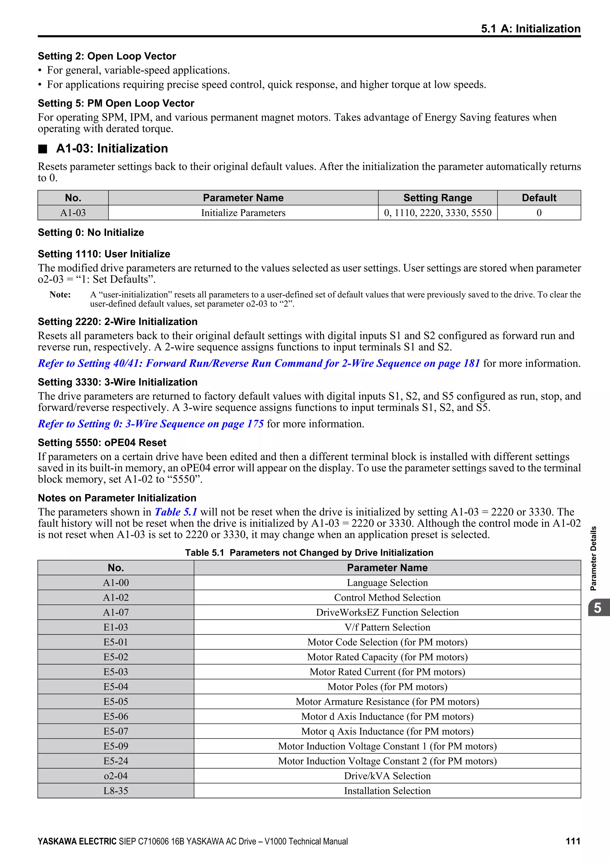


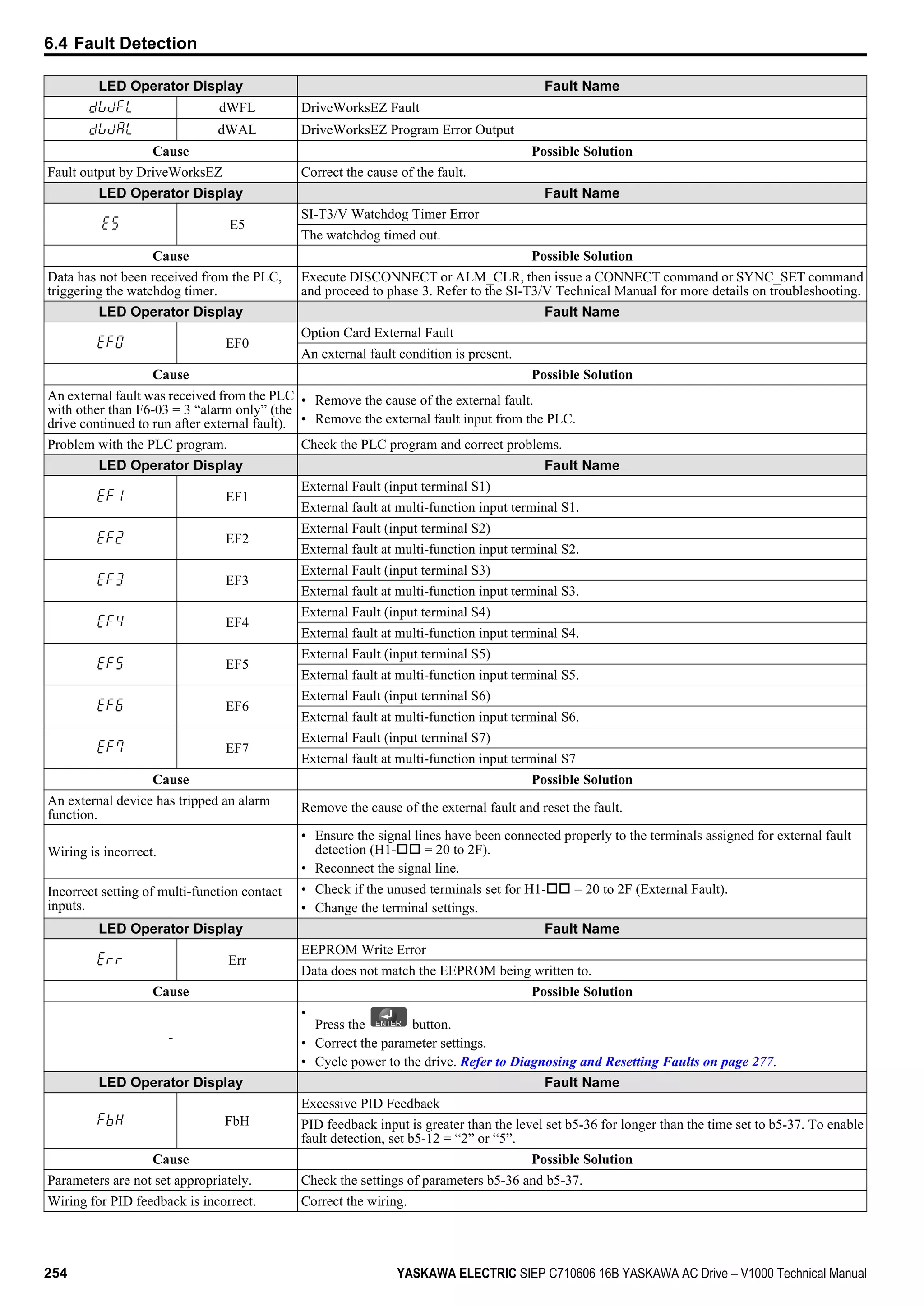
![Setting a Variable Carrier Frequency (V/f Control only)
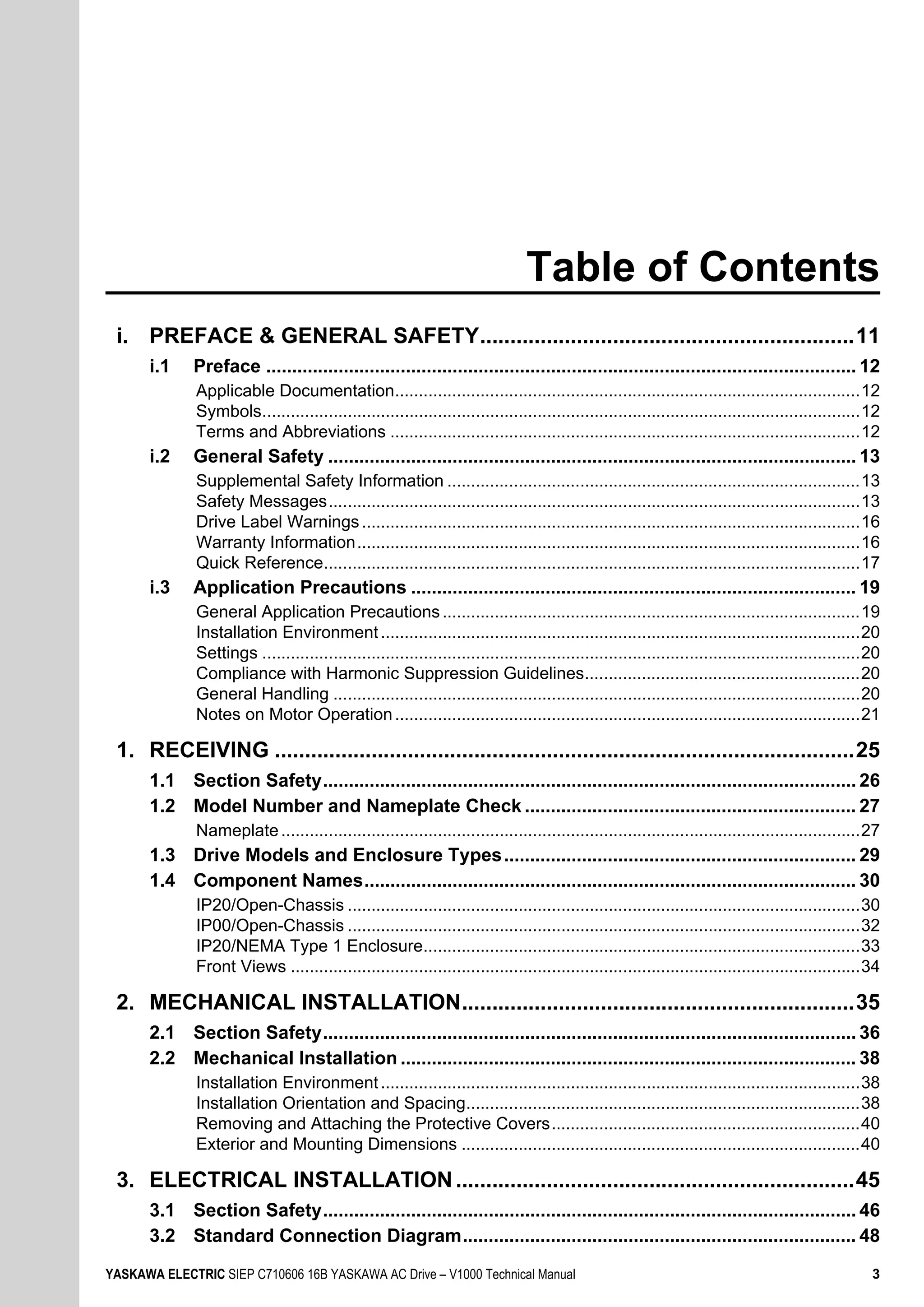
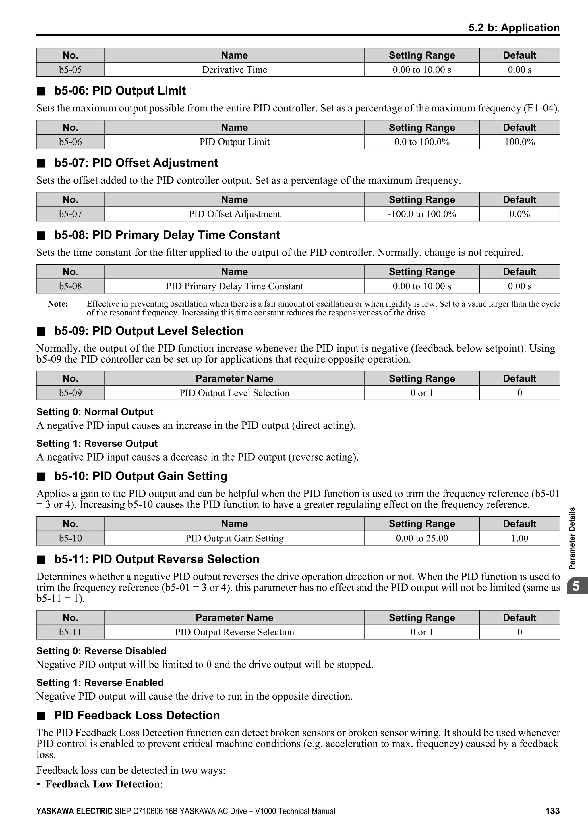
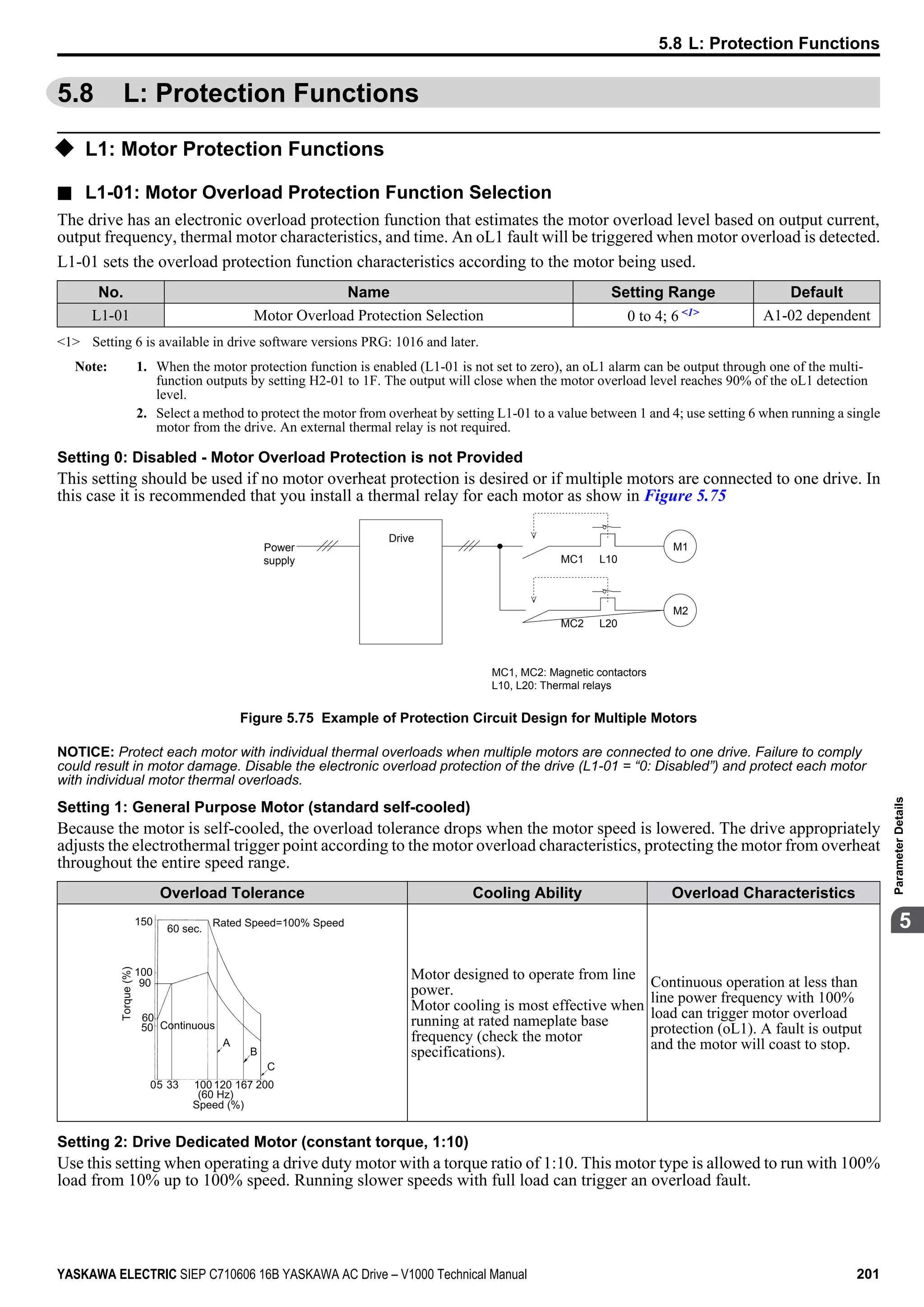
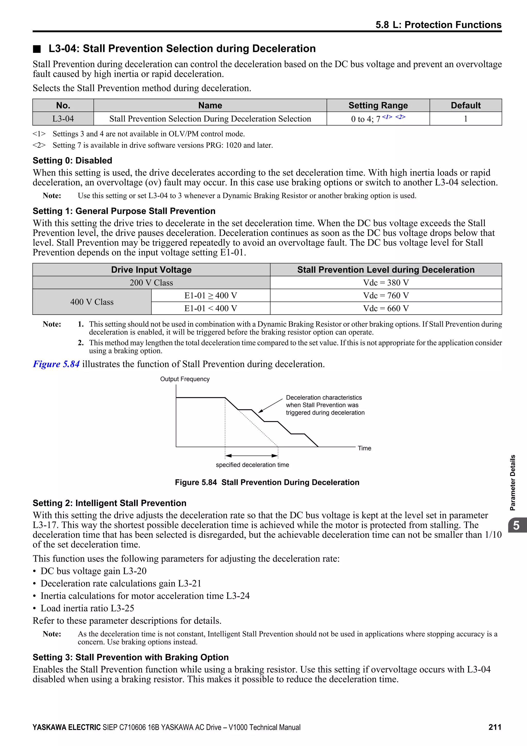
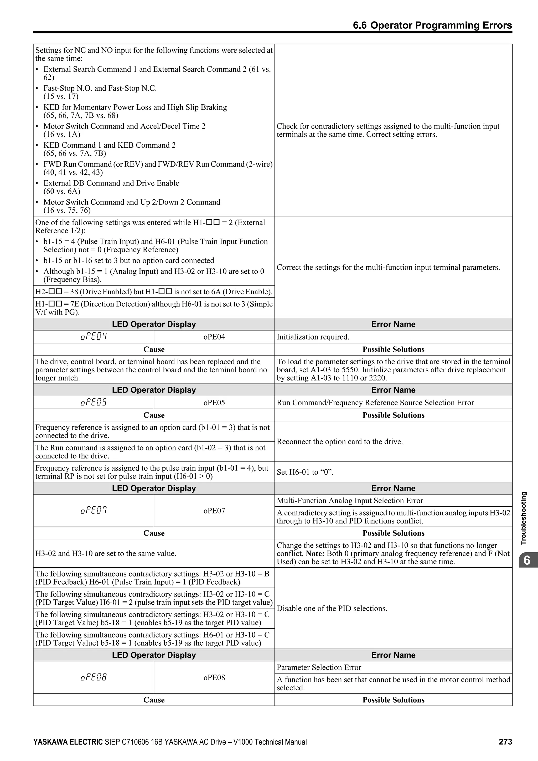
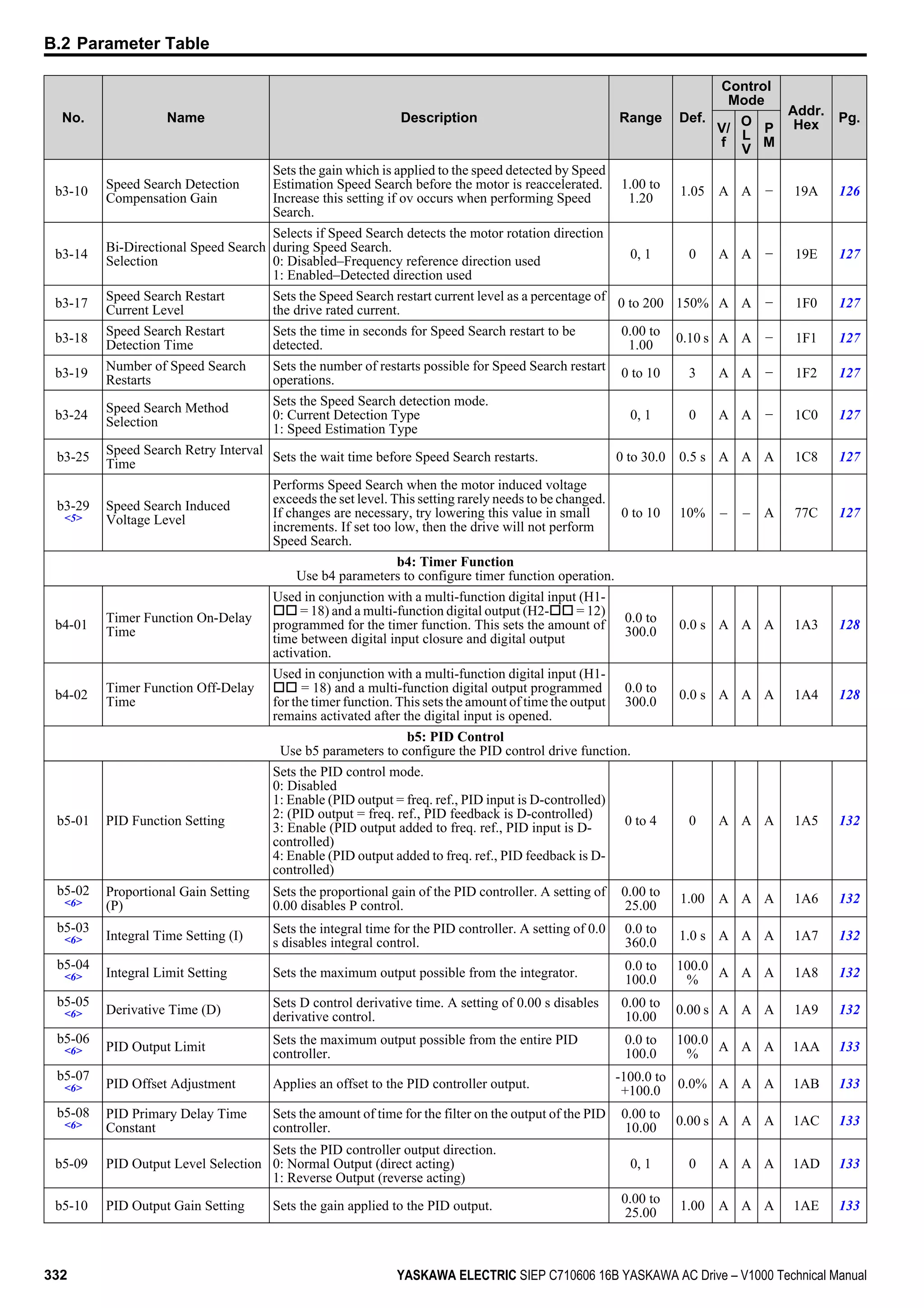
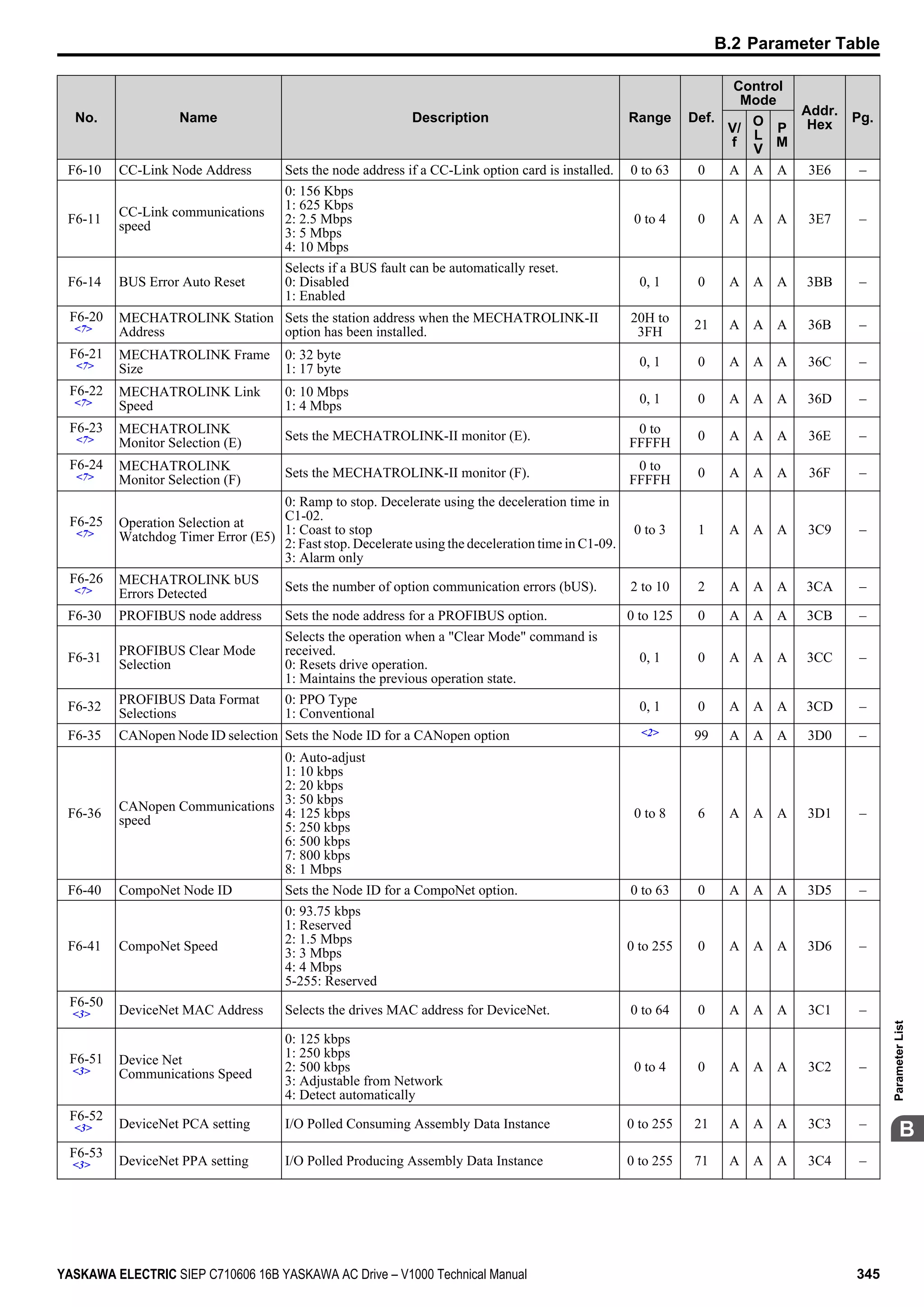
In V/f Control, the carrier frequency can be set up to change linearly with the output frequency. In this case the upper and
lower limits for the carrier frequency and the carrier frequency proportional gain (C6-03, C6-04, C6-05) have to be set as
shown in Figure 5.31.
C6-03
C6-04
E1-04
x C6-05 x K*
Output Frequency
Output
Frequency
Max Output Frequency
Carrier Frequency
Figure 5.31 Carrier Frequency Changes Relative to Output Frequency
K is a coefficient determined by the value of C6-03:
• 10.0 kHz > C6-03 ≥ to 5.0 kHz: K = 2
• 5.0 kHz > C6-03: K = 1
• C6-03 ≥ 10.0 kHz: K = 3
Note: 1. A carrier frequency error (oPE11) will occur when the carrier frequency proportional gain is greater than 6 while C6-03 is less than
C6-04.
2. When C6-05 is set lower than 7, C6-04 is disabled and the carrier frequency will be fixed to the value set in C6-03.
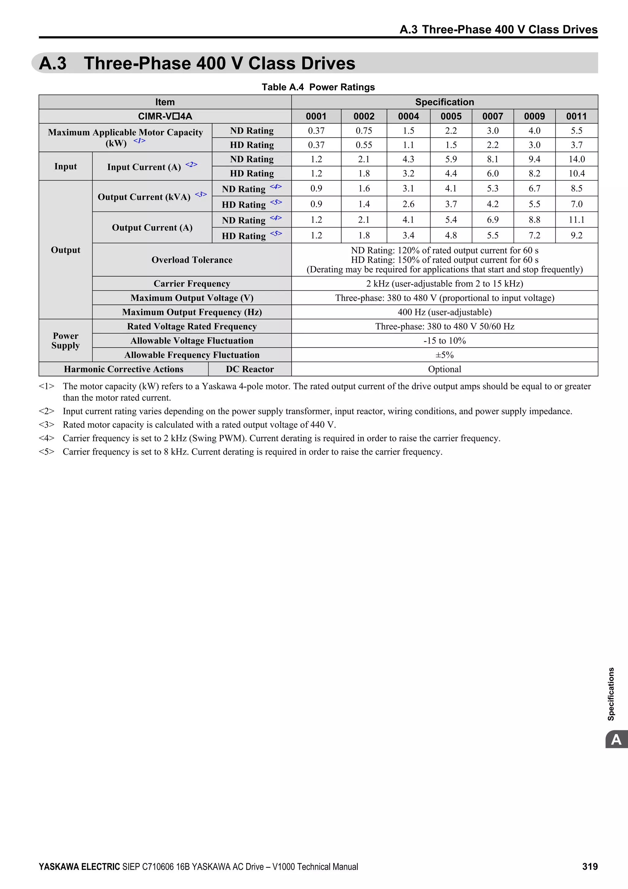
n Rated Current Depending on Carrier Frequency
The tables below show the drive output current depending on the carrier frequency settings. The 2 kHz value is equal to
the Normal Duty rated current, the 8/10 kHz value is equal to the Heavy Duty rated current. The carrier frequency
determines the output current linearly. Use the data below to calculate output current values for carrier frequencies not
listed in the tables.
Note: In Heavy Duty mode the maximum rated output current is equal to the 8/10 kHz value, even if the carrier frequency is reduced.
Table 5.12 Drives with Heavy Duty Default Carrier Frequency of 10 kHz
200 V Single Phase Units 200 V Three Phase Units
Model Vo
Rated Current [A]
Model Vo
Rated Current [A]
2 kHz 10 kHz 15 kHz 2 kHz 10 kHz 15 kHz
BA0001 1.2 0.8 0.6 2A0001 1.2 0.8 0.6
BA0002 1.9 1.6 1.3 2A0002 1.9 1.6 1.3
BA0003 3.5 3.0 2.4 2A0004 3.5 3.0 2.4
BA0006 6.0 5.0 4.0 2A0006 6.0 5.0 4.0
Table 5.13 Drives with Heavy Duty Default Carrier Frequency of 8 kHz
200 V Single Phase Units 200 V Three Phase Units 400 V Three Phase Units
Model
Vo
Rated Current [A] Model
Vo
Rated Current [A] Model
Vo
Rated Current [A]
2 kHz 8 kHz 15 kHz 2 kHz 8 kHz 15 kHz 2 kHz 8 kHz 15 kHz
BA0010 9.6 8.0 6.4 2A0008 8.0 6.9 5.5 4A0001 1.2 1.2 0.7
BA0012 12.0 11.0 8.8 2A0010 9.6 8.0 6.4 4A0002 2.1 1.8 1.1
BA0018 17.5 17.5 14.0 2A0012 12.0 11.0 8.8 4A0004 4.1 3.4 2.0
— — — — 2A0018 17.5 14.0 11.2 4A0005 5.4 4.8 2.9
— — — — 2A0020 19.6 17.5 14.0 4A0007 6.9 5.5 3.3
— — — — 2A0030 30.0 25.0 20.0 4A0009 8.8 7.2 4.3
— — — — 2A0040 40.0 33.0 26.4 4A0011 11.1 9.2 5.5
— — — — 2A0056 56.0 47.0 37.6 4A0018 17.5 14.8 8.9
— — — — 2A0069 69.0 60.0 48.0 4A0023 23.0 18.0 10.8
— — — — — — — — 4A0031 31.0 24.0 14.4
— — — — — — — — 4A0038 38.0 31.0 18.6
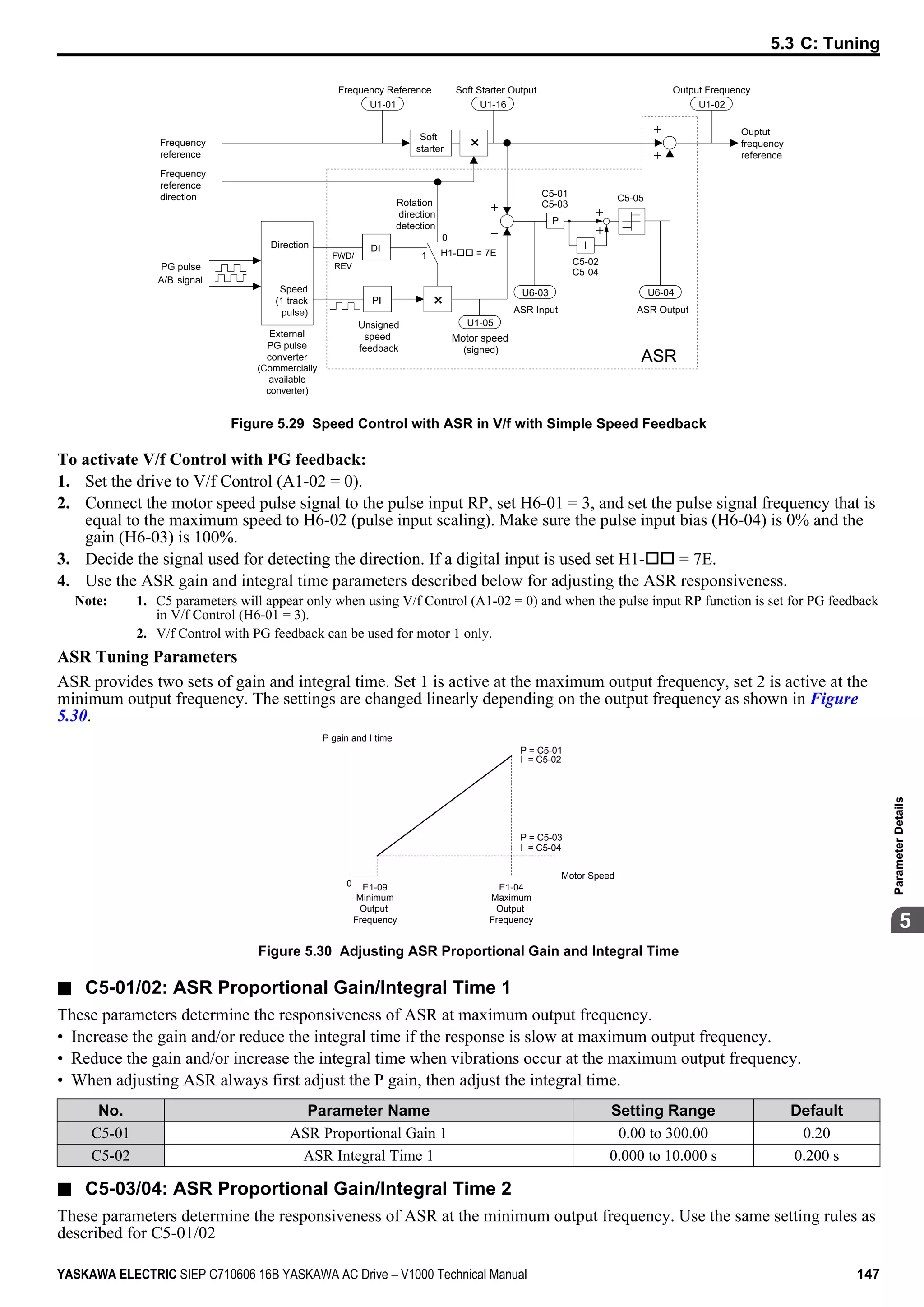
5.3 C: Tuning
150 YASKAWA ELECTRIC SIEP C710606 16B YASKAWA AC Drive – V1000 Technical Manual](https://image.slidesharecdn.com/yaskawav1000instuctionmanuelinenglish-160910020601/75/Yaskawa-V1000-Instuction-Manuel-150-2048.jpg)


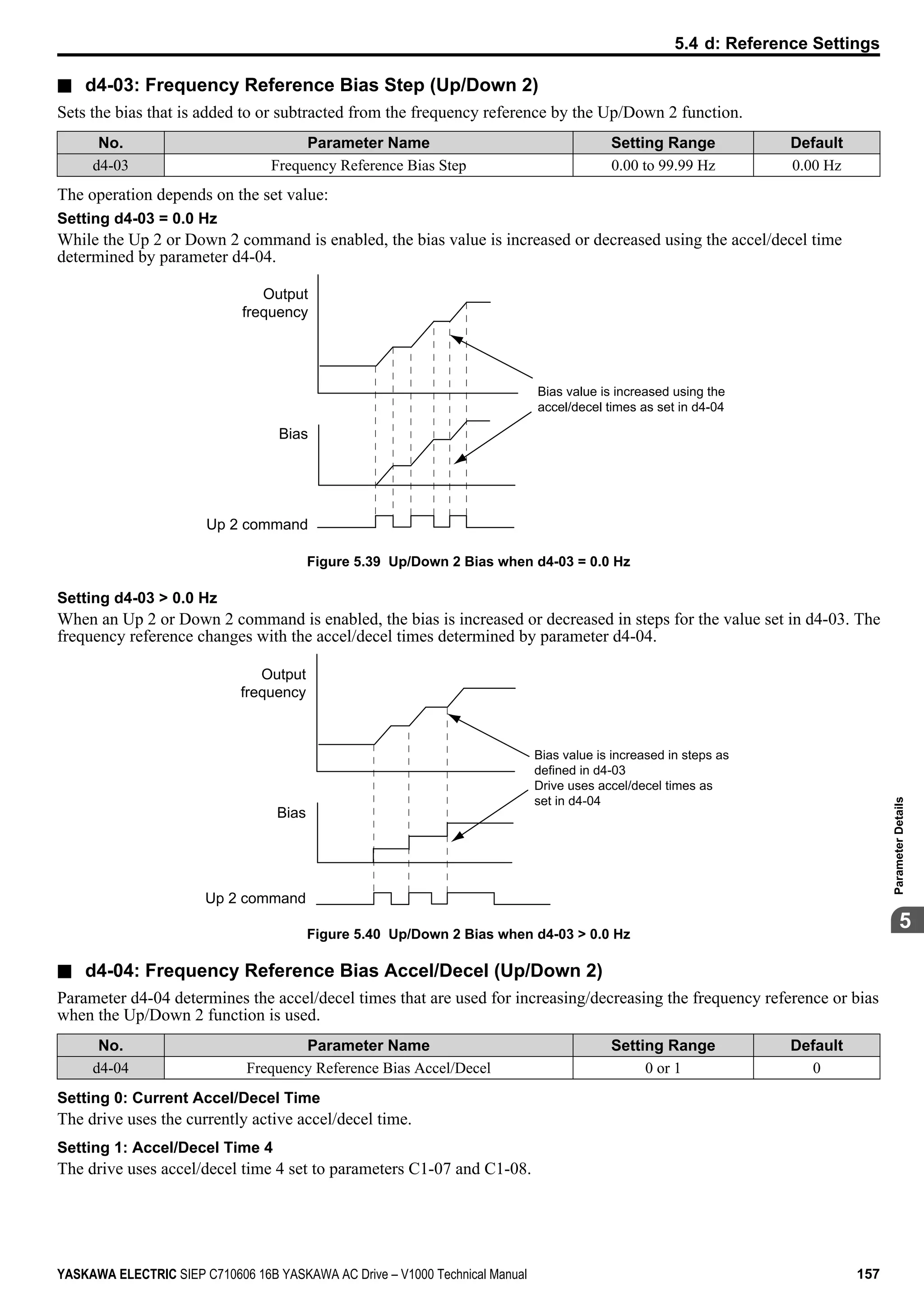

![n d4-09: Frequency Reference Bias Lower Limit (Up/Down 2)
Parameter d4-08 sets the lower limit of the Up/Down 2 bias (monitor U6-20) and the value that can be saved in parameter
d4-06. Set this parameter to an appropriate value before using the Up/Down 2 function.
Note: When the frequency reference is set by the digital operator (b1-01 = 0) and d4-01 = 1, the bias value will be added to the frequency
reference if no Up/Down 2 command is received for 5 s, and will be reset to 0 afterwards. If the bias is increased using the Up 2
command, once it is added to the frequency reference the speed can not be reduced with a Down 2 command if the limit set in d4-09
is 0. In this case make sure to set a negative lower limit in d4-09 to allow speed reduction.
No. Parameter Name Setting Range Default
d4-09 Frequency Reference Bias Lower Limit -99.9 to 0.0% 0.0%
n d4-10: Up/Down Frequency Reference Limit Selection
Selects how the lower frequency limit is set when the Up/Down function is used. Refer to Setting 10/11: Up/Down
Command on page 177 for details on the Up/Down function in combination with frequency reference limits.
Setting 0: Lower Limit is Determined by d2-02 or Analog Input
The lower frequency reference limit is determined by the higher value of both, parameter d2-02 or an analog input that is
programmed for “Frequency Bias” (H3-02/10 = 0).
Note: If the external reference change over function (H1-oo = 2) used to switch between Up/Down function and analog input as reference
source, the analog value would become the lower reference limit when the Up/Down reference is active. Change d4-10 to 1 to make
the Up/Down function independent of the analog input value.
Setting 1: Lower Limit is Determined by Parameter d2-02
Only parameter d2-02 sets the lower frequency reference limit.
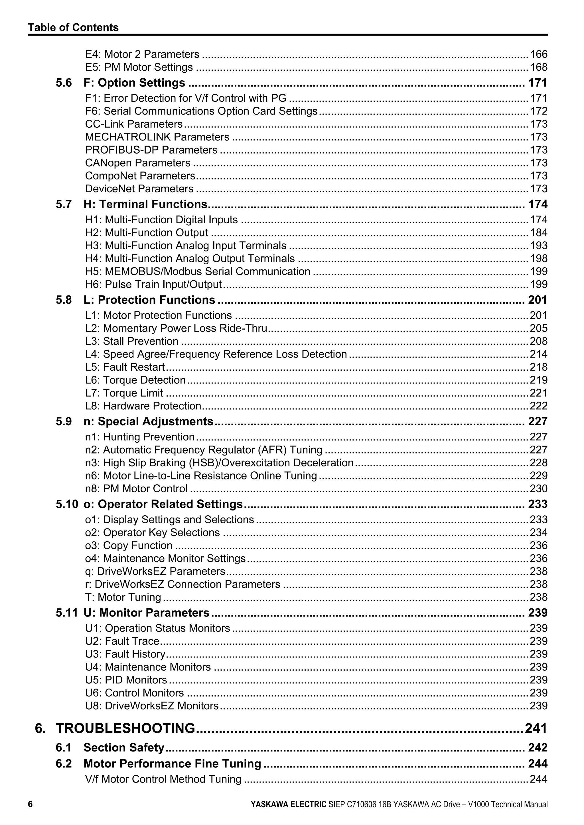
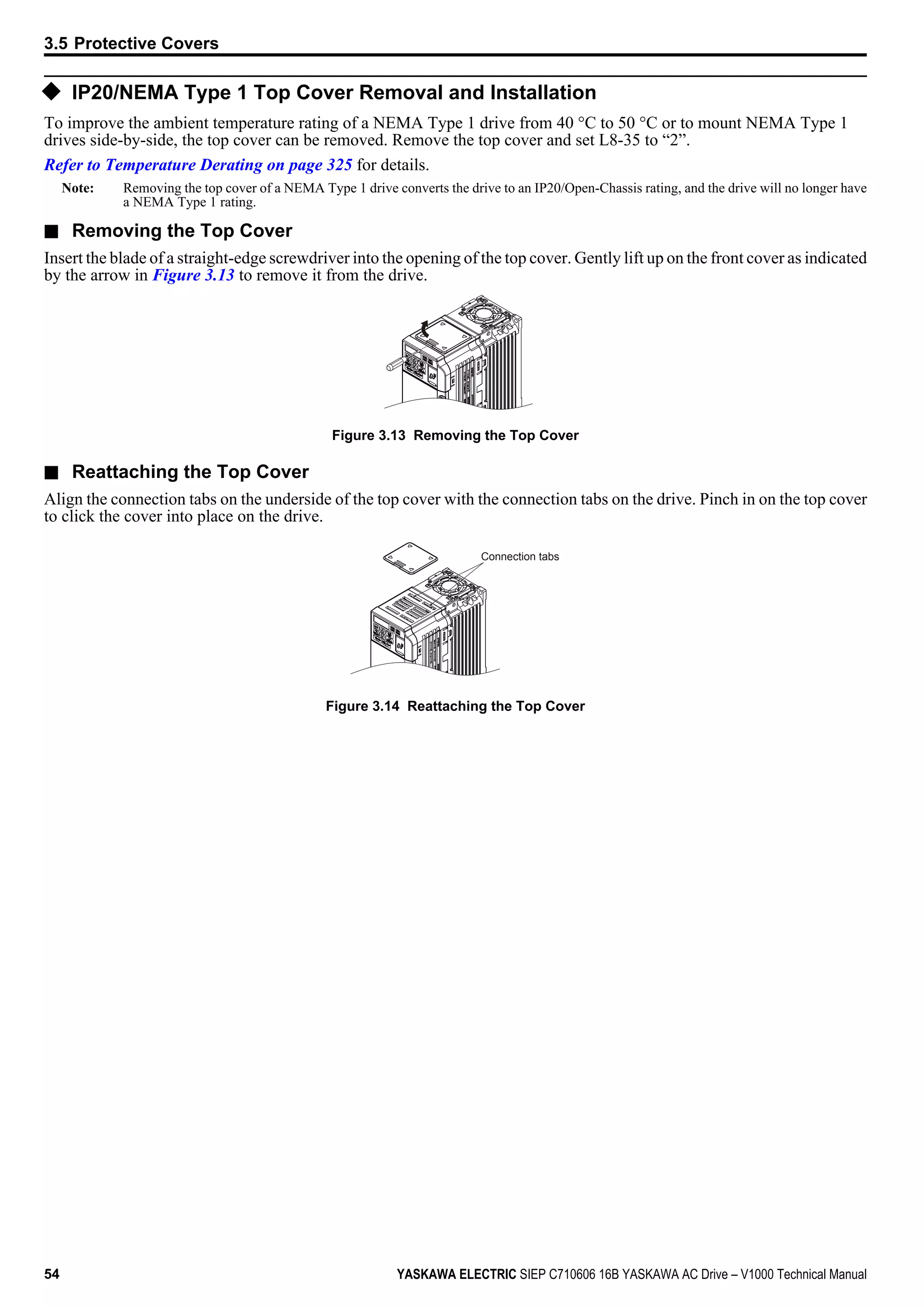
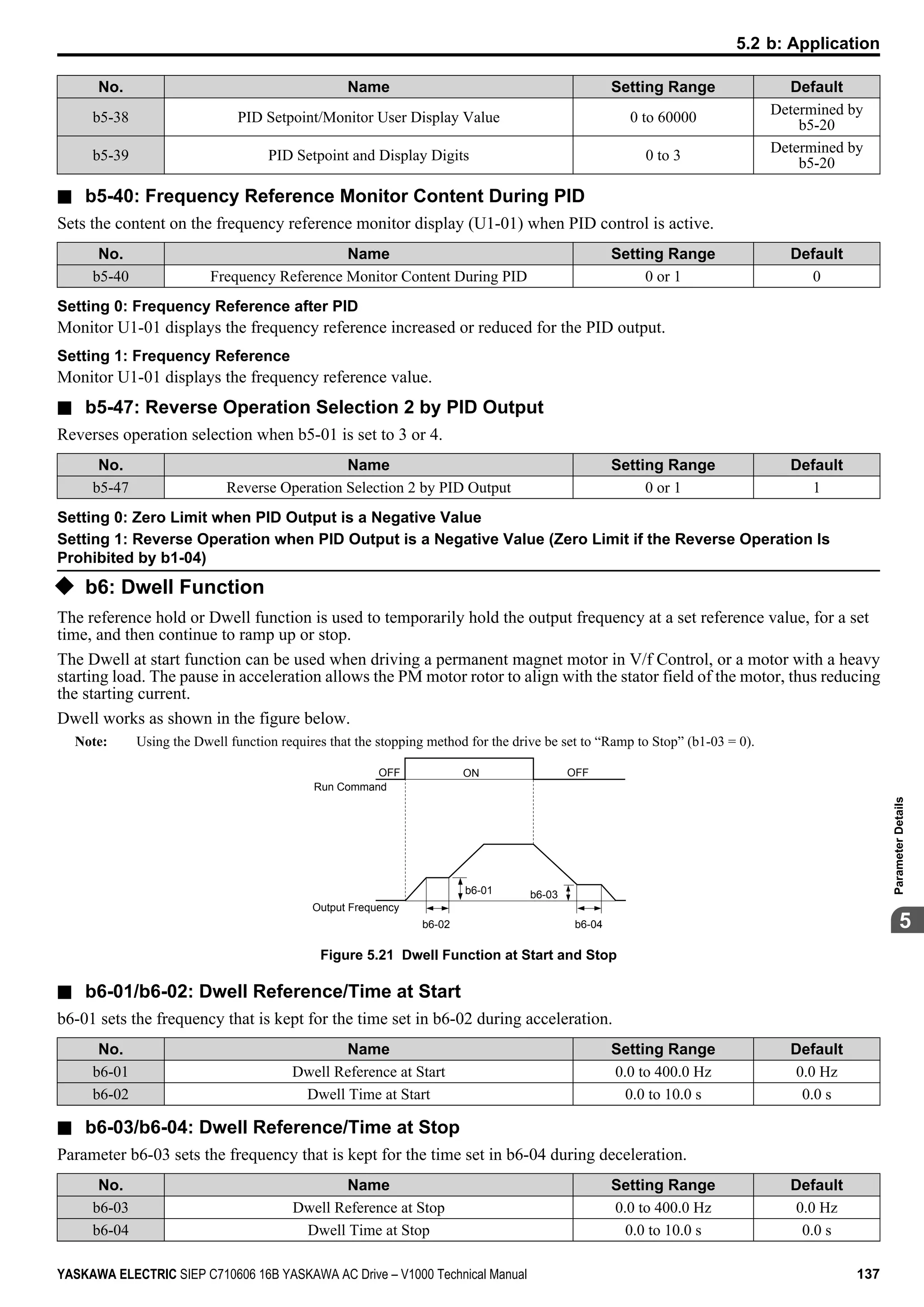
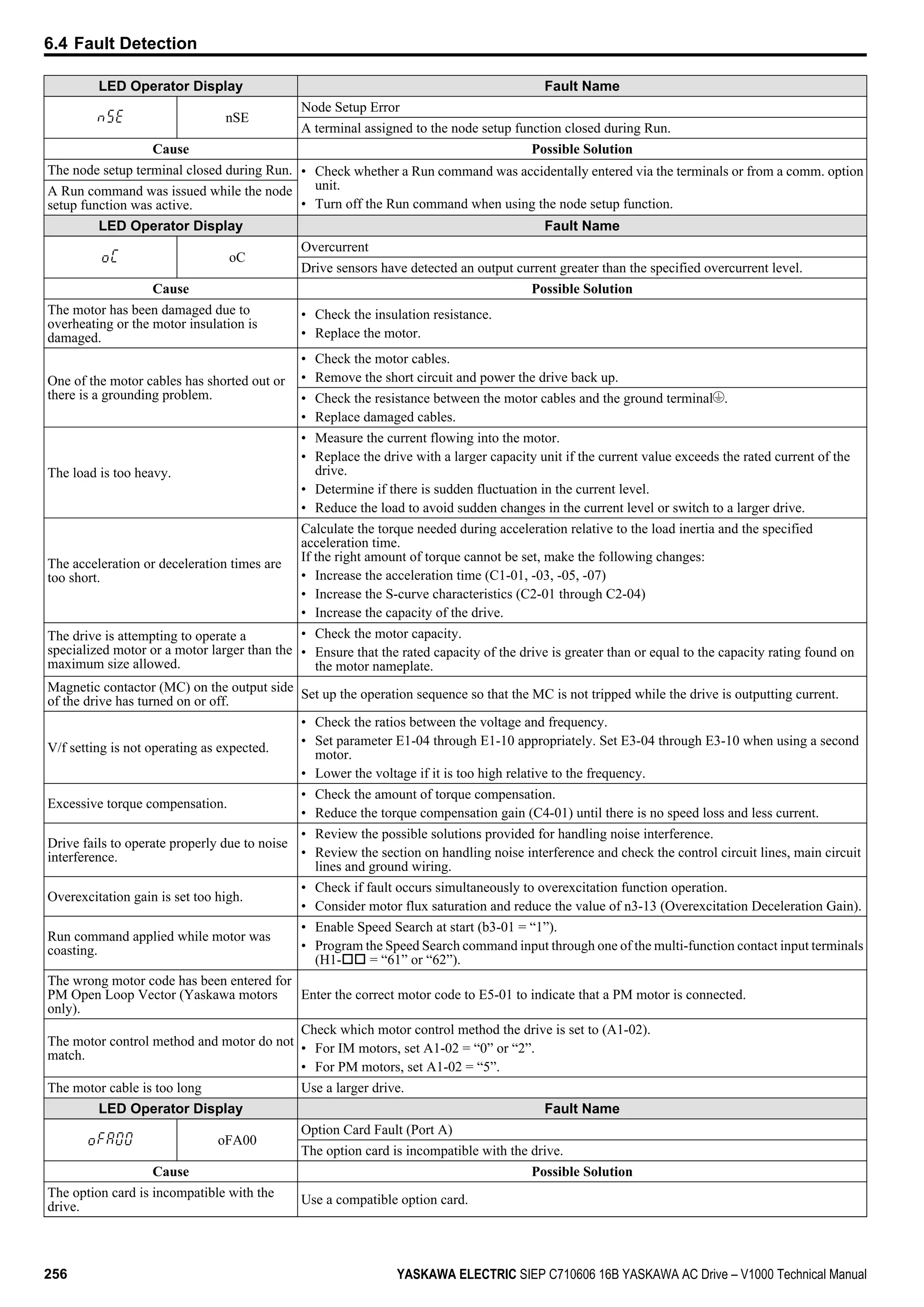
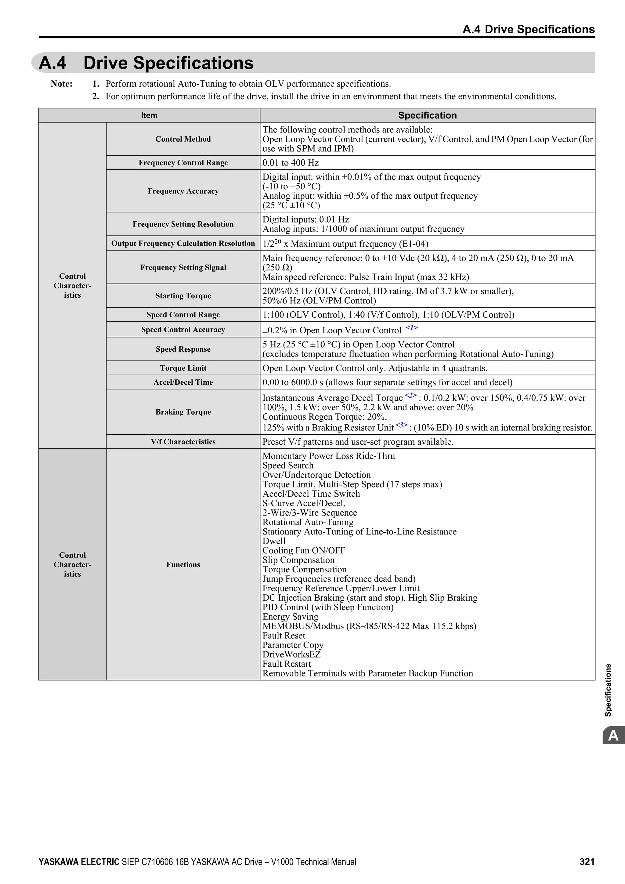
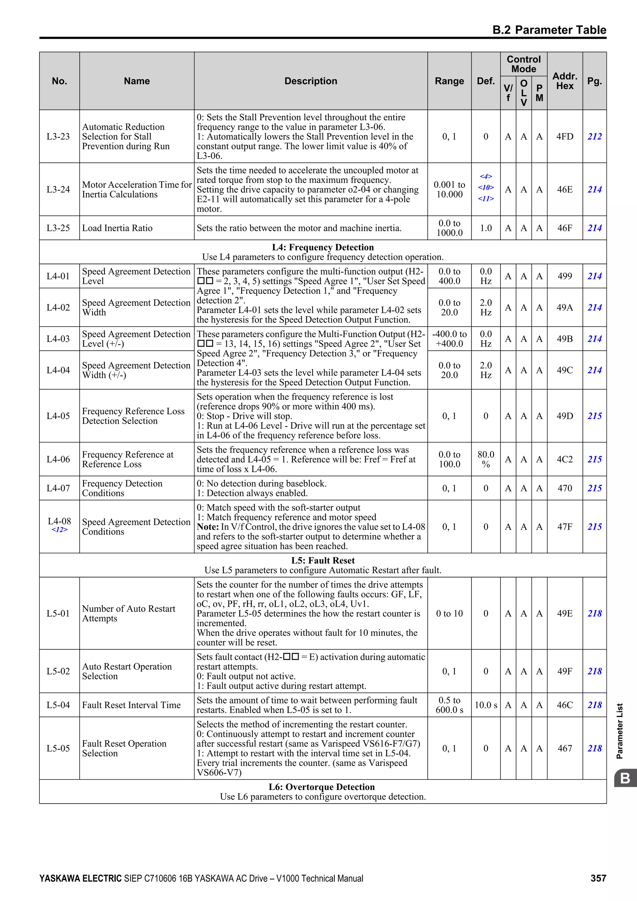
u d7: Offset Frequencies
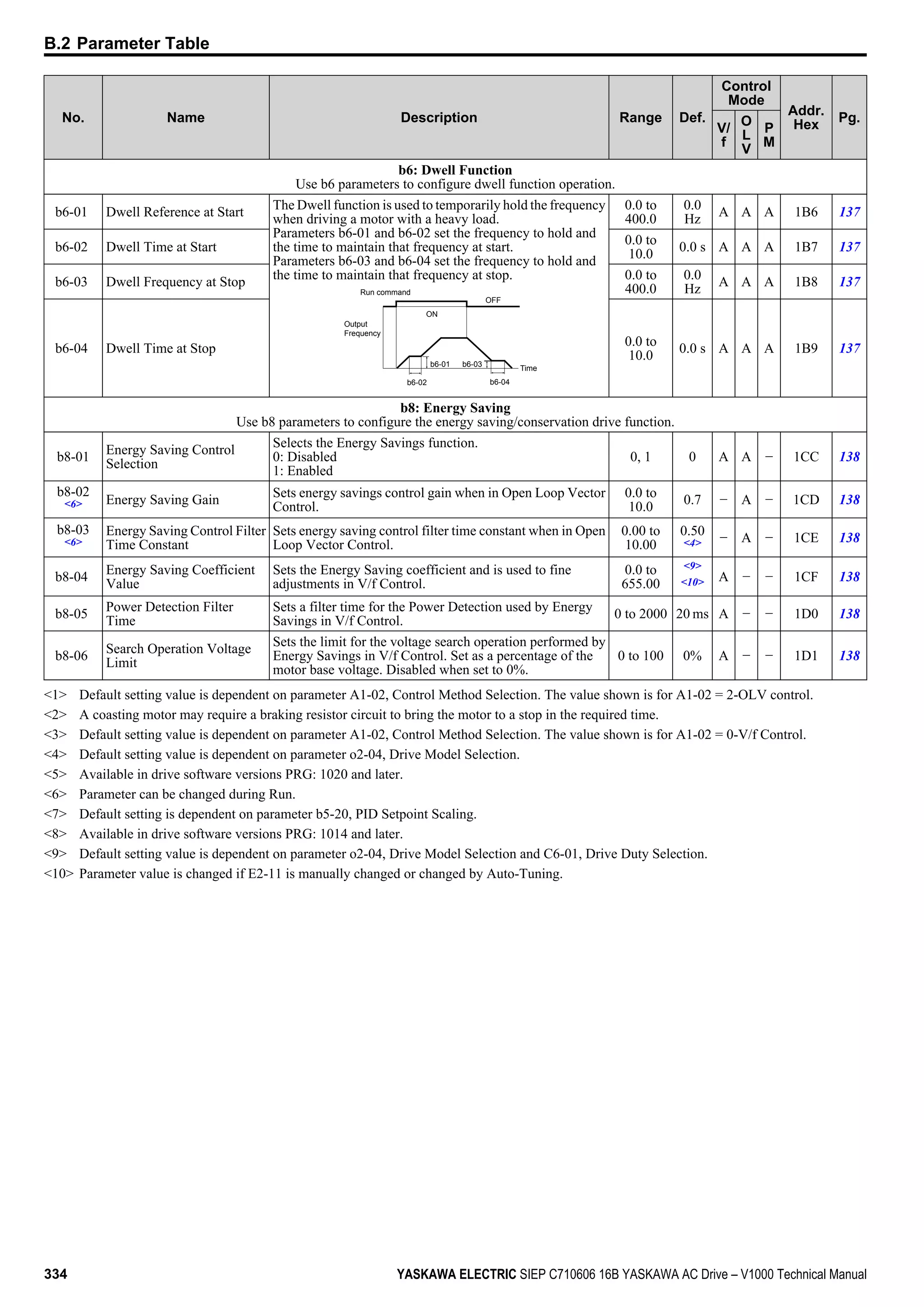
n d7-01 to d7-03: Offset Frequency 1 to 3
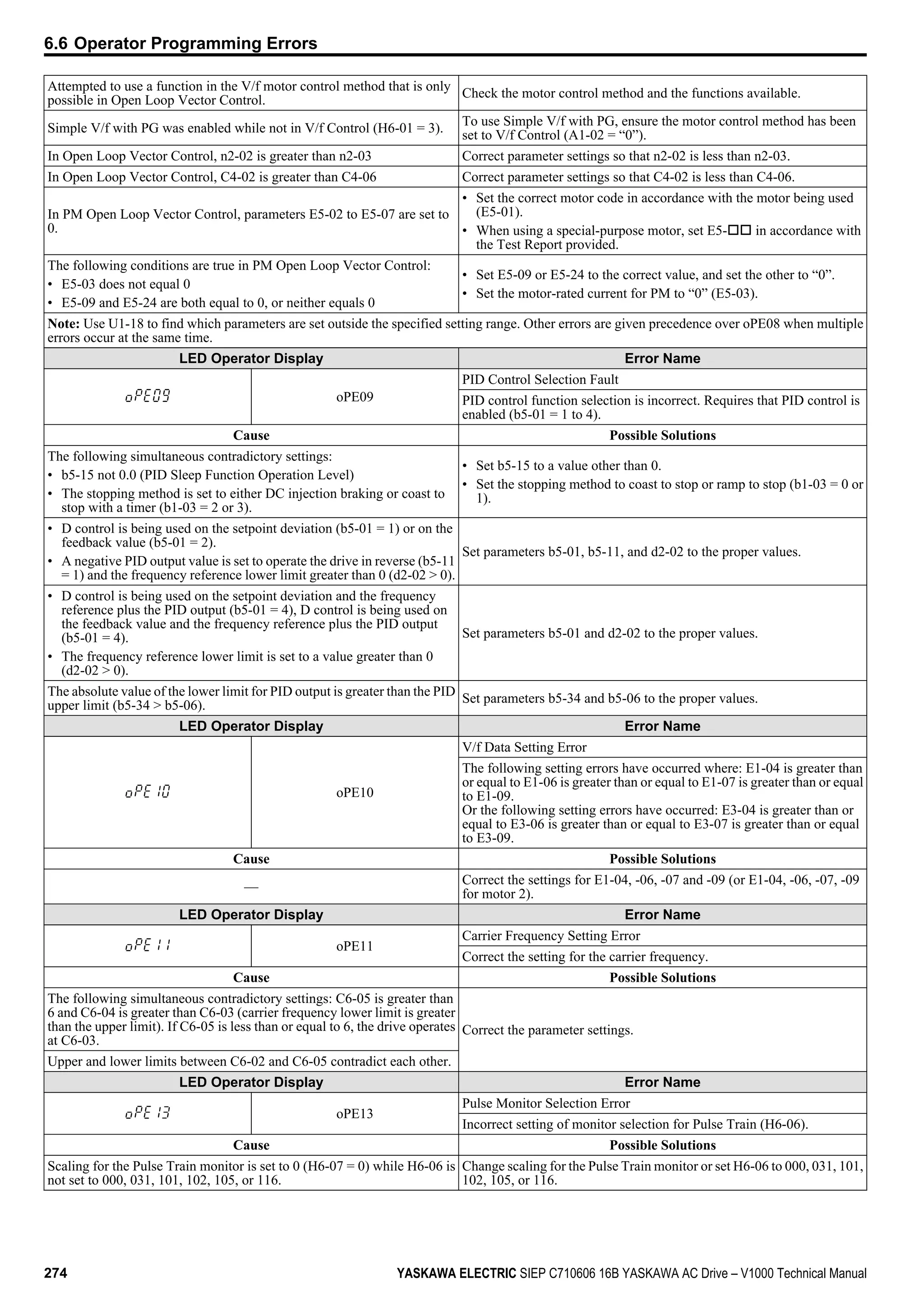
Three different offset values can be added to the frequency reference. They can be selected using digital inputs programmed
for Offset frequency 1, 2 and 3 (H1-oo = 44, 45, 46). The selected offset values are added if two or all three inputs are
closed at the same time.
Note: This function can be used to replace the “Trim Control” function (H1-oo = 1C/1D) of earlier Yaskawa drives.
No. Parameter Name Setting Range Default
d7-01 Offset Frequency 1 -100.0 to 100.0% 0%
d7-02 Offset Frequency 2 -100.0 to 100.0% 0%
d7-03 Offset Frequency 3 -100.0 to 100.0% 0%
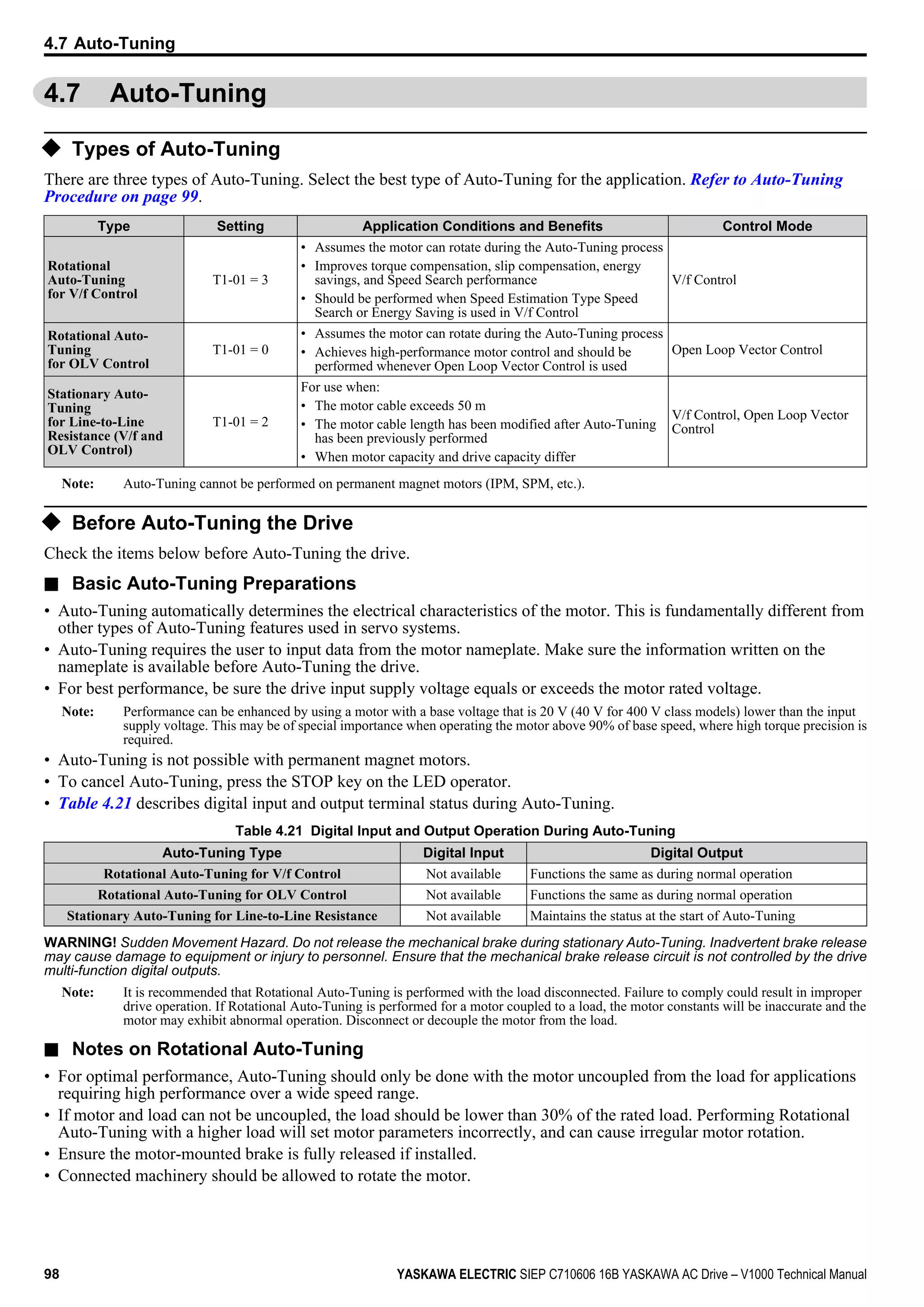
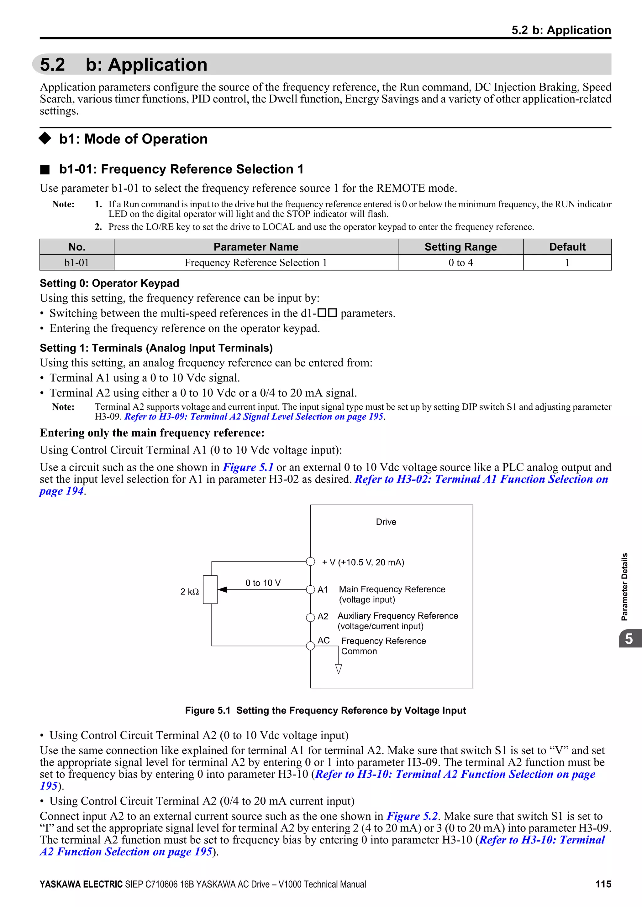
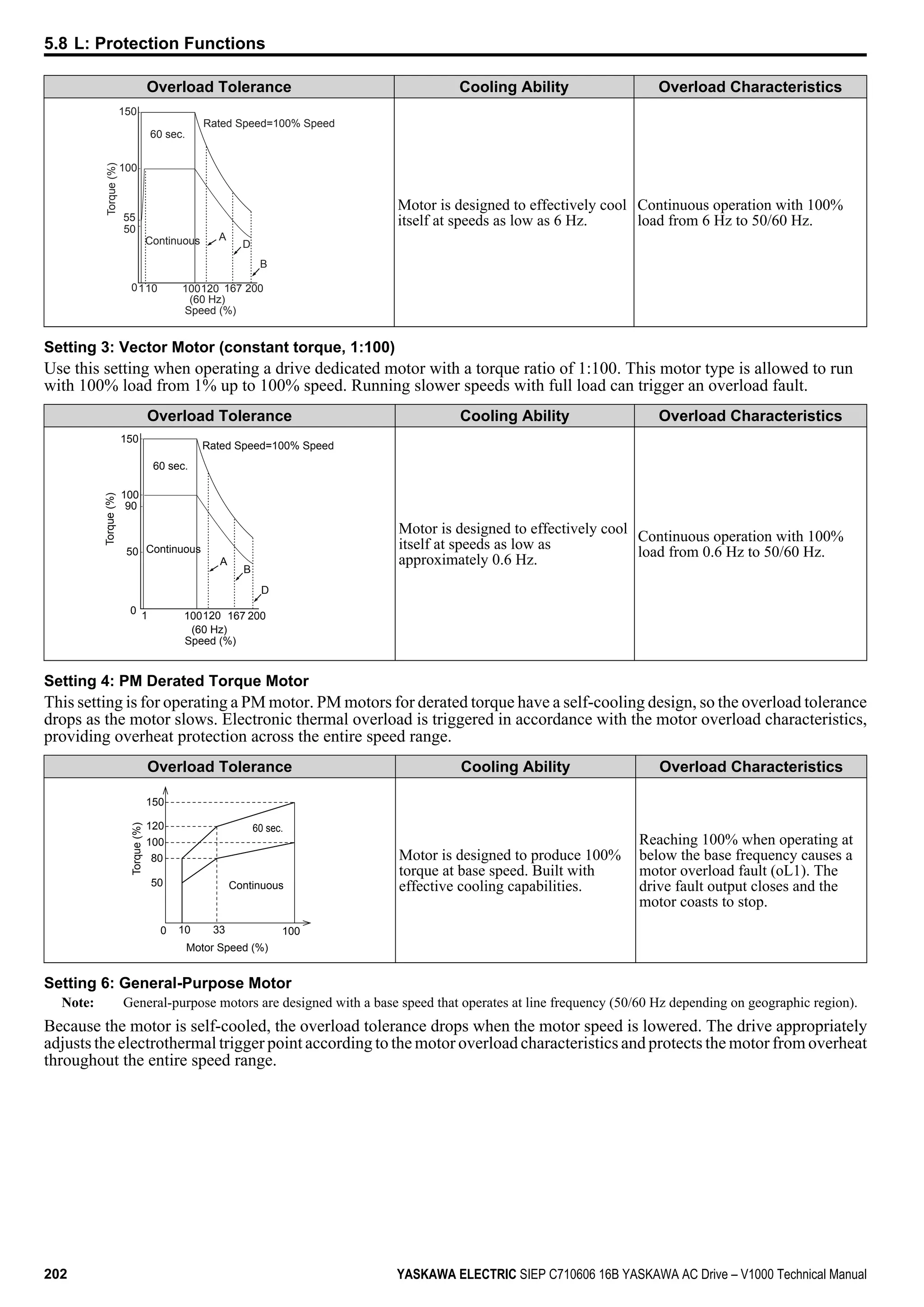
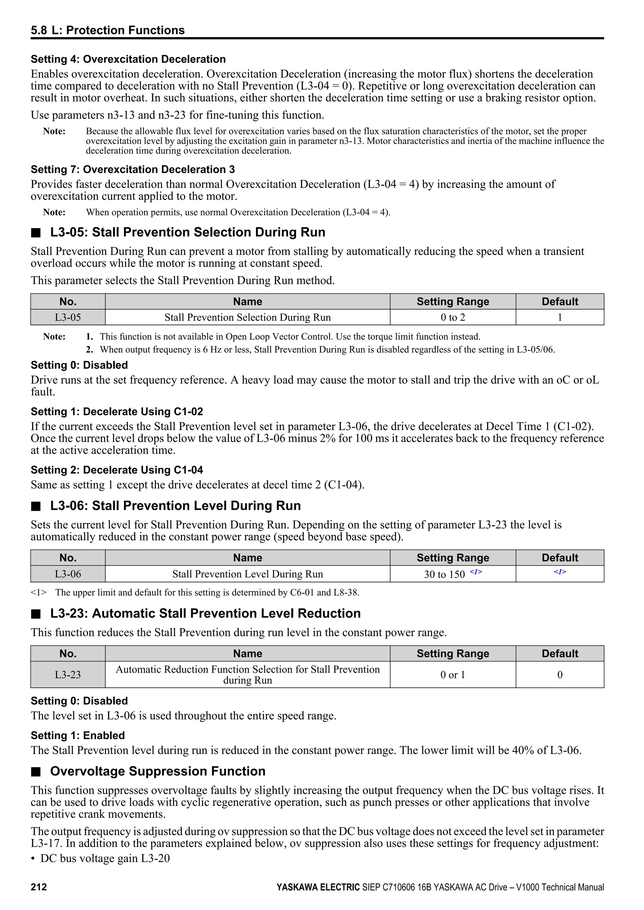
Figure 5.41 illustrates the Offset Frequency Function.
Frequency
reference
Offset Frequency 1 [d7-01]
(Signed)
Offset Frequency 2 [d7-02]
(Signed)
Offset Frequency 3 [d7-03]
(Signed)
Multi-function
input (44) = on
Multi-function
input (45) = on
Multi-function
input (46) = on
SFS
Frequency
reference after
soft starter
Figure 5.41 Offset Frequency Operation
5.4 d: Reference Settings
YASKAWA ELECTRIC SIEP C710606 16B YASKAWA AC Drive – V1000 Technical Manual 159
5
ParameterDetails](https://image.slidesharecdn.com/yaskawav1000instuctionmanuelinenglish-160910020601/75/Yaskawa-V1000-Instuction-Manuel-159-2048.jpg)


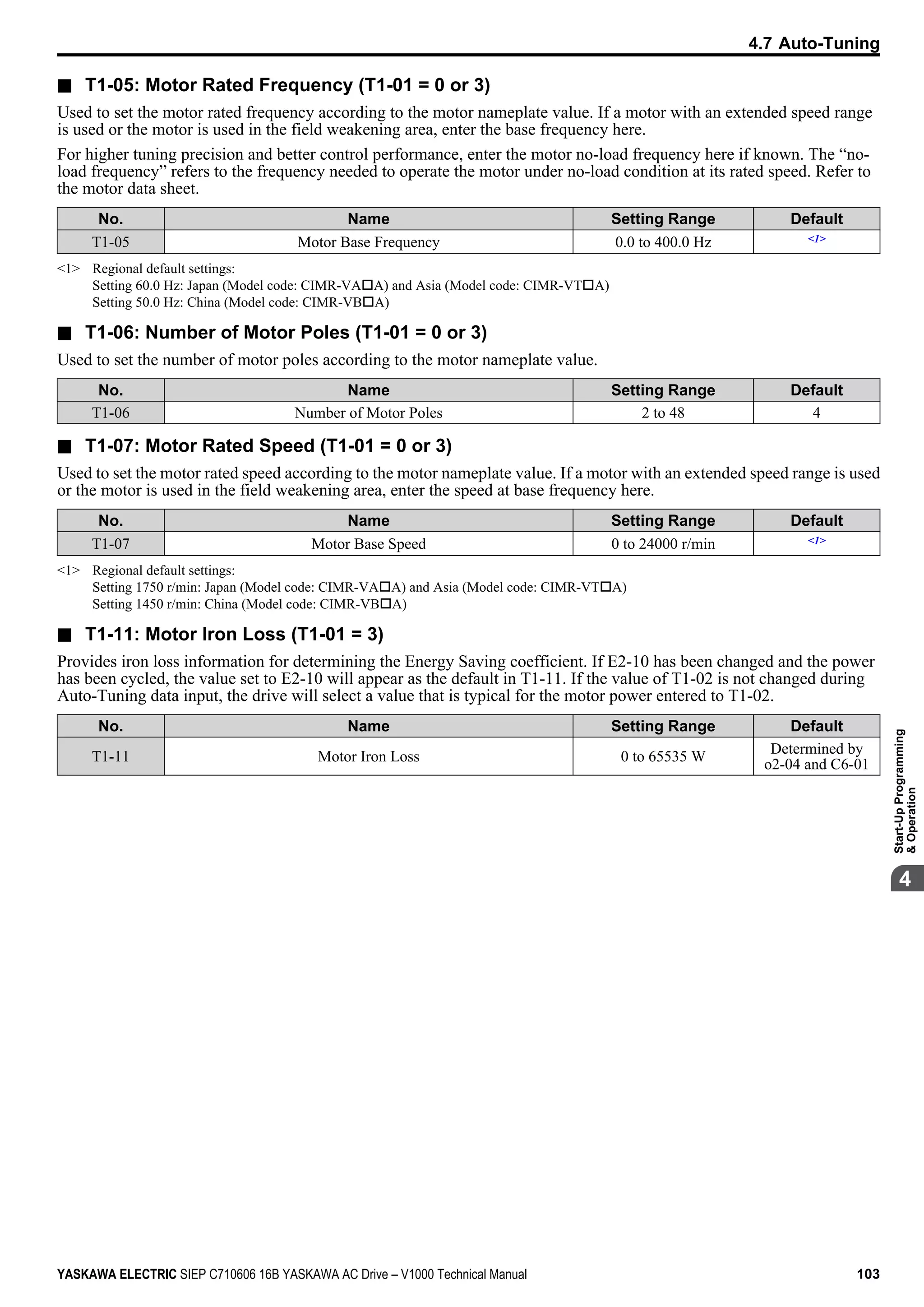
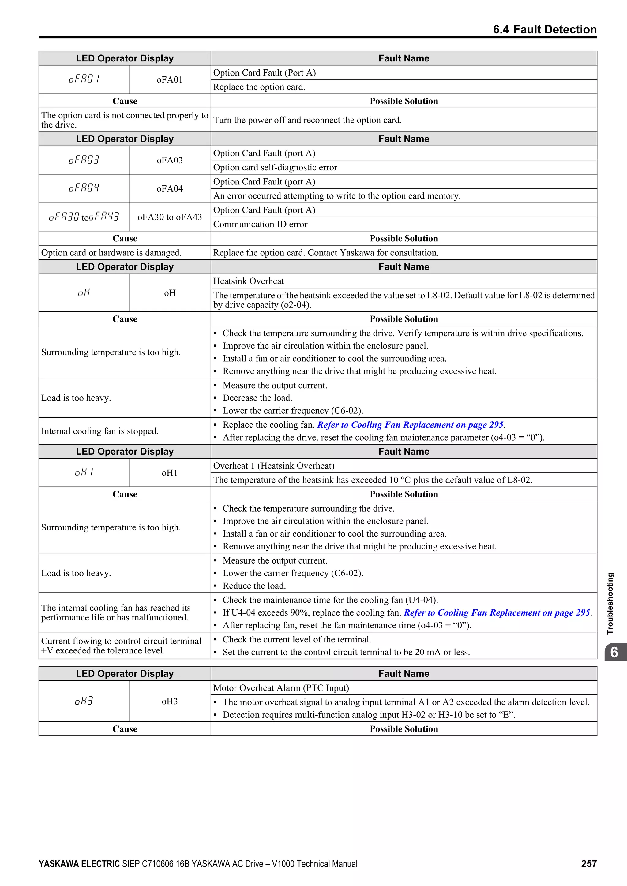
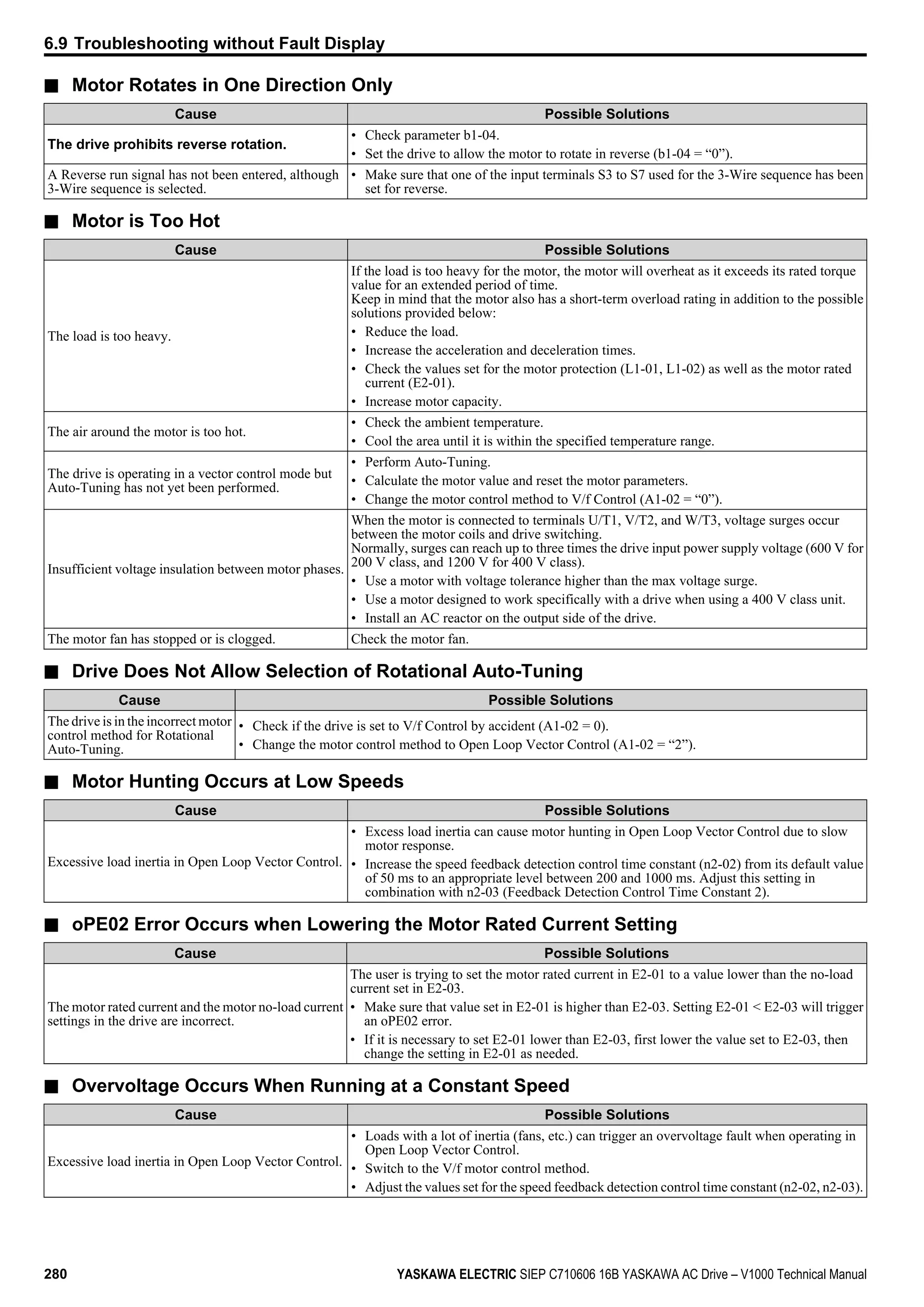
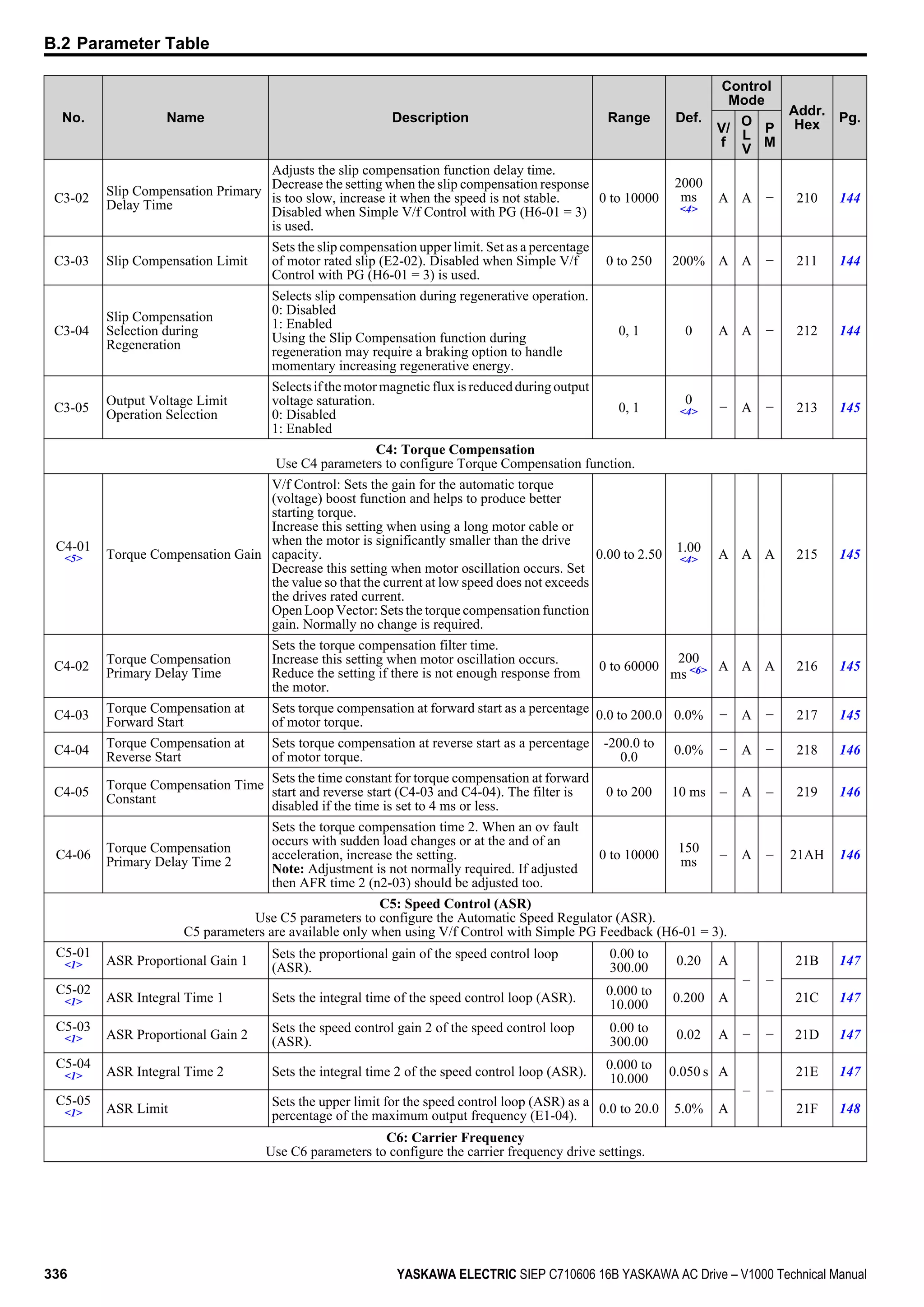
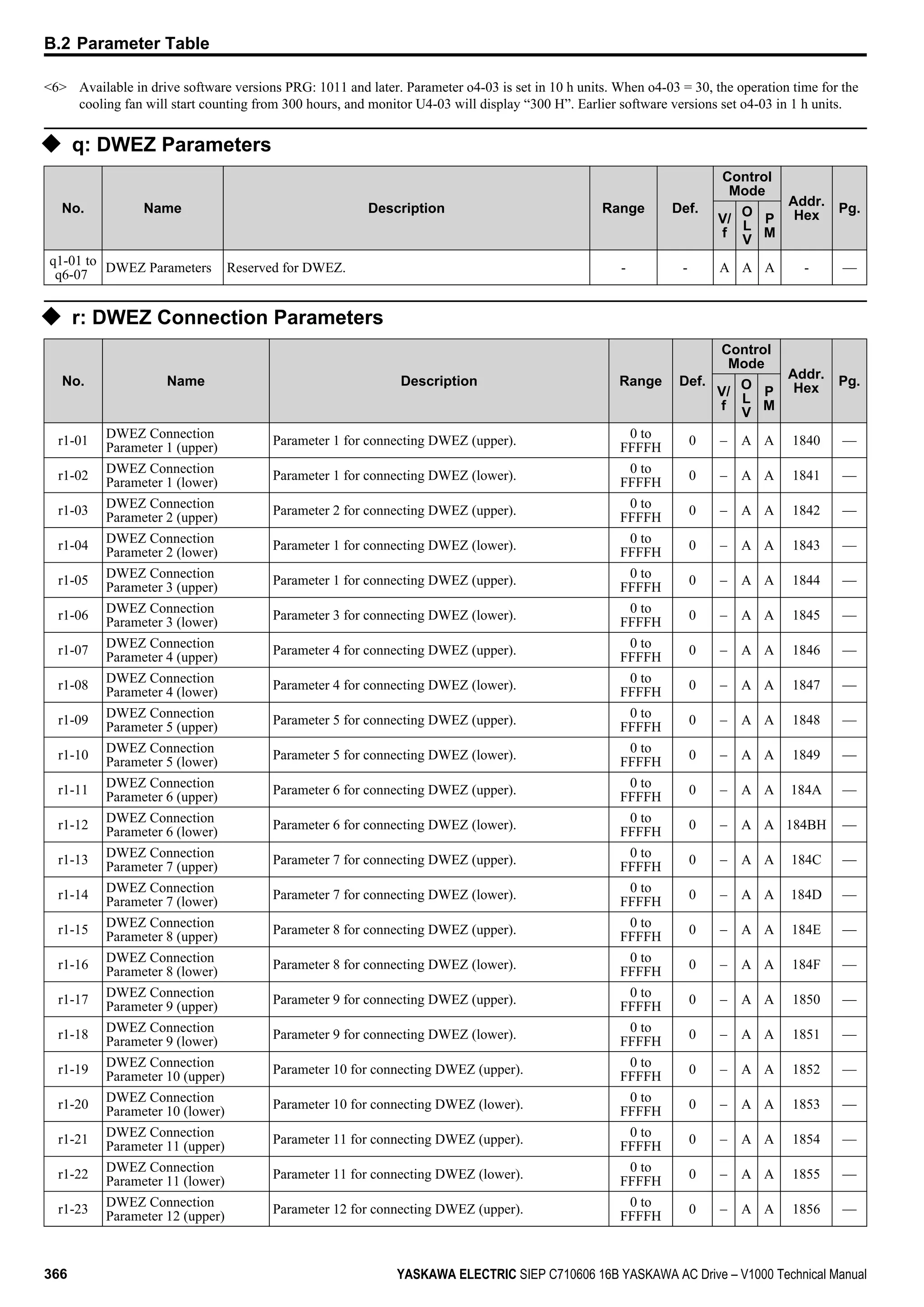
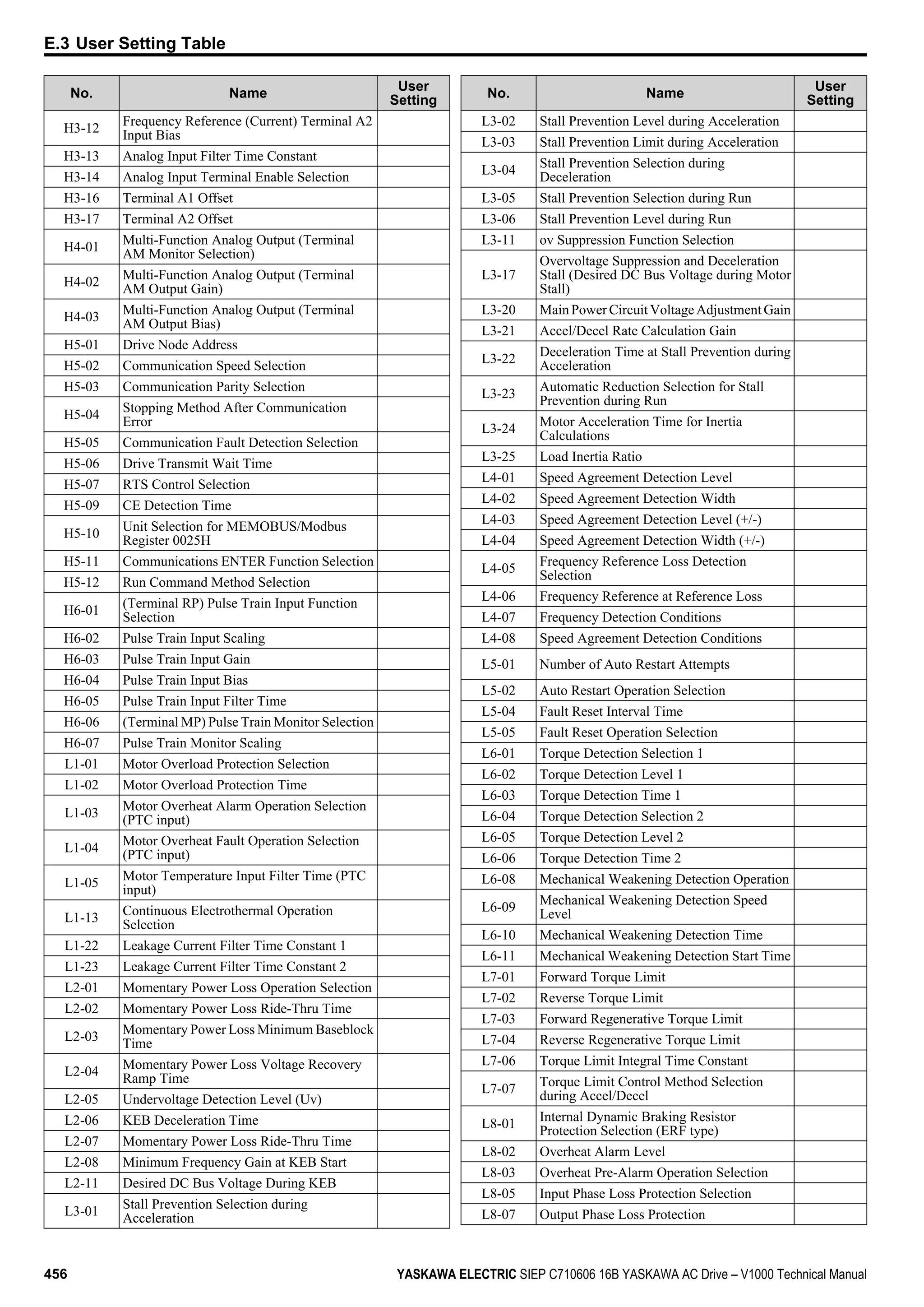
![2. Change E2-01 only after changing the value set to E2-03. Setting E2-01 < E2-03 will trigger an oPE02 error.
n E2-02: Motor Rated Slip
Sets the motor rated slip in Hz. This value is automatically set during Rotational Auto-Tuning.
No. Parameter Name Setting Range Default
E2-02 Motor Rated Slip 0.00 to 20.00 Hz
Depending on
o2-04
If Auto-Tuning can not be performed calculate the motor rated slip using the information written on the motor nameplate
and the formula below:
E2-02 = f - (n x p)/120
(f: rated frequency (Hz), n: rated motor speed (r/min), p: number of motor poles)
n E2-03: Motor No-Load Current
Set E2-03 to the motor no-load current at rated voltage and rated frequency. If Rotational Auto-Tuning completes
successfully, this value is automatically calculated. If Auto-Tuning can not be performed, contact the motor manufacturer
for information about the no-load current.
No. Parameter Name Setting Range Default
E2-03 Motor No-Load Current
0 to [E2-01]
(unit: 0.01 A)
Depending on
o2-04
Note: The resolution of E2-03 depends on the rated output power of the drive. If a drive is set up for 7.5 kW and lower rated output power
(ND or HD rating) the value will have two decimal places. It will have one decimal place if a drive is set up for 11 kW and higher.
n E2-04: Number of Motor Poles
Set the number of motor poles to E2-04. This value must be entered during Auto-Tuning, and will automatically be saved
to E2-04 if Auto-Tuning completes successfully.
No. Parameter Name Setting Range Default
E2-04 Number of Motor Poles 2 to 48 poles 4 poles
n E2-05: Motor Line-to-Line Resistance
Sets the line-to-line resistance of the motor stator winding. If the Auto-Tuning completes successfully, this value is
automatically calculated. Remember this value must be entered as line-line and not line-neutral.
No. Parameter Name Setting Range Default
E2-05 Motor Line-to-Line Resistance 0.000 to 65.000 Ω
Depending on
o2-04
Note: The setting range becomes 0.00 to 130.00 when using VoBA0002, Vo2A0002, Vo4A0001 and smaller.
If Auto-Tuning is not possible, then contact the motor manufacturer to find out the line-to-line resistance or measure it
manually. When using the manufacturer Motor Test Report, calculate E2-05 by the formulas below.
• E-type insulation: Multiply 0.92 times the resistance value (Ω) listed on the Test Report at 75 °C
• B-type insulation: Multiply 0.92 times the resistance value (Ω) listed on the Test Report at 75 °C.
• F-type insulation: Multiply 0.87 times the resistance value (Ω) listed on the Test Report at 115 °C.
n E2-06: Motor Leakage Inductance
Sets the voltage drop due to motor leakage inductance as a percentage of motor rated voltage.
No. Parameter Name Setting Range Default
E2-06 Motor Leakage Inductance 0.0 to 40.0%
Depending on
o2-04
n E2-07: Motor Iron-Core Saturation Coefficient 1
This parameter sets the motor iron saturation coefficient at 50% of the magnetic flux. If Rotational Auto-Tuning completes
successfully, then this value is automatically calculated.
No. Parameter Name Setting Range Default
E2-07 Motor Iron-Core Saturation Coefficient 1 0.00 to 0.50 0.50
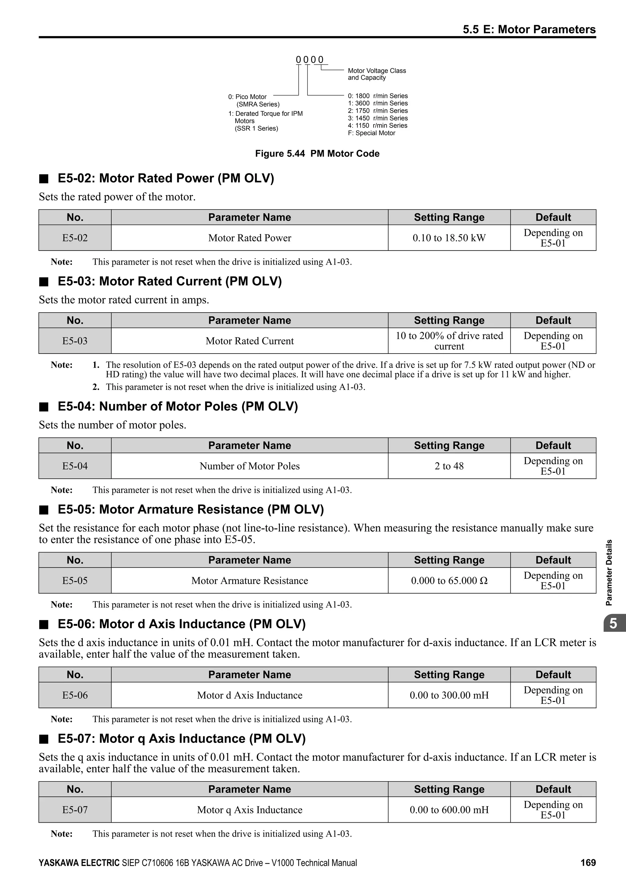
5.5 E: Motor Parameters
164 YASKAWA ELECTRIC SIEP C710606 16B YASKAWA AC Drive – V1000 Technical Manual](https://image.slidesharecdn.com/yaskawav1000instuctionmanuelinenglish-160910020601/75/Yaskawa-V1000-Instuction-Manuel-164-2048.jpg)

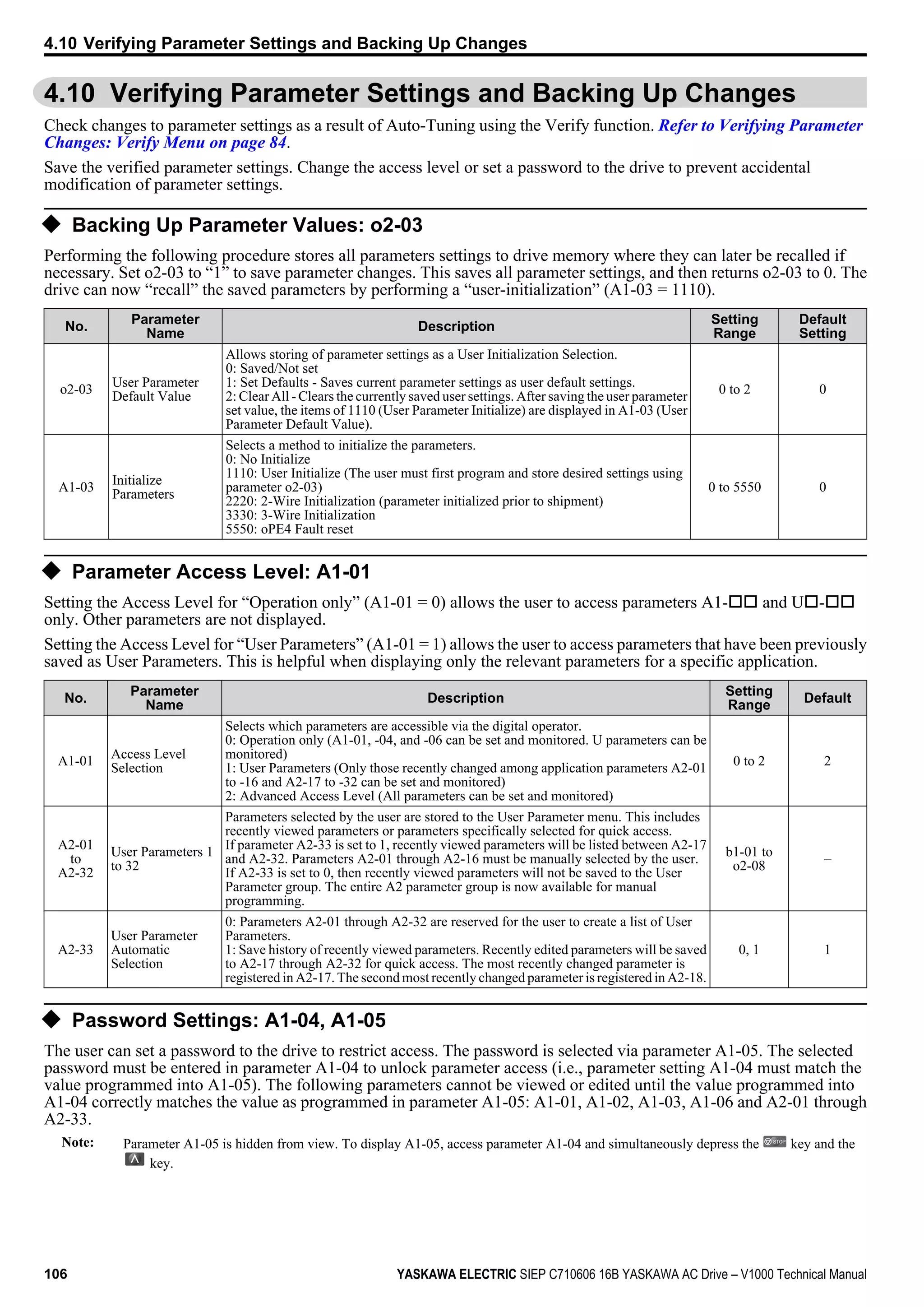
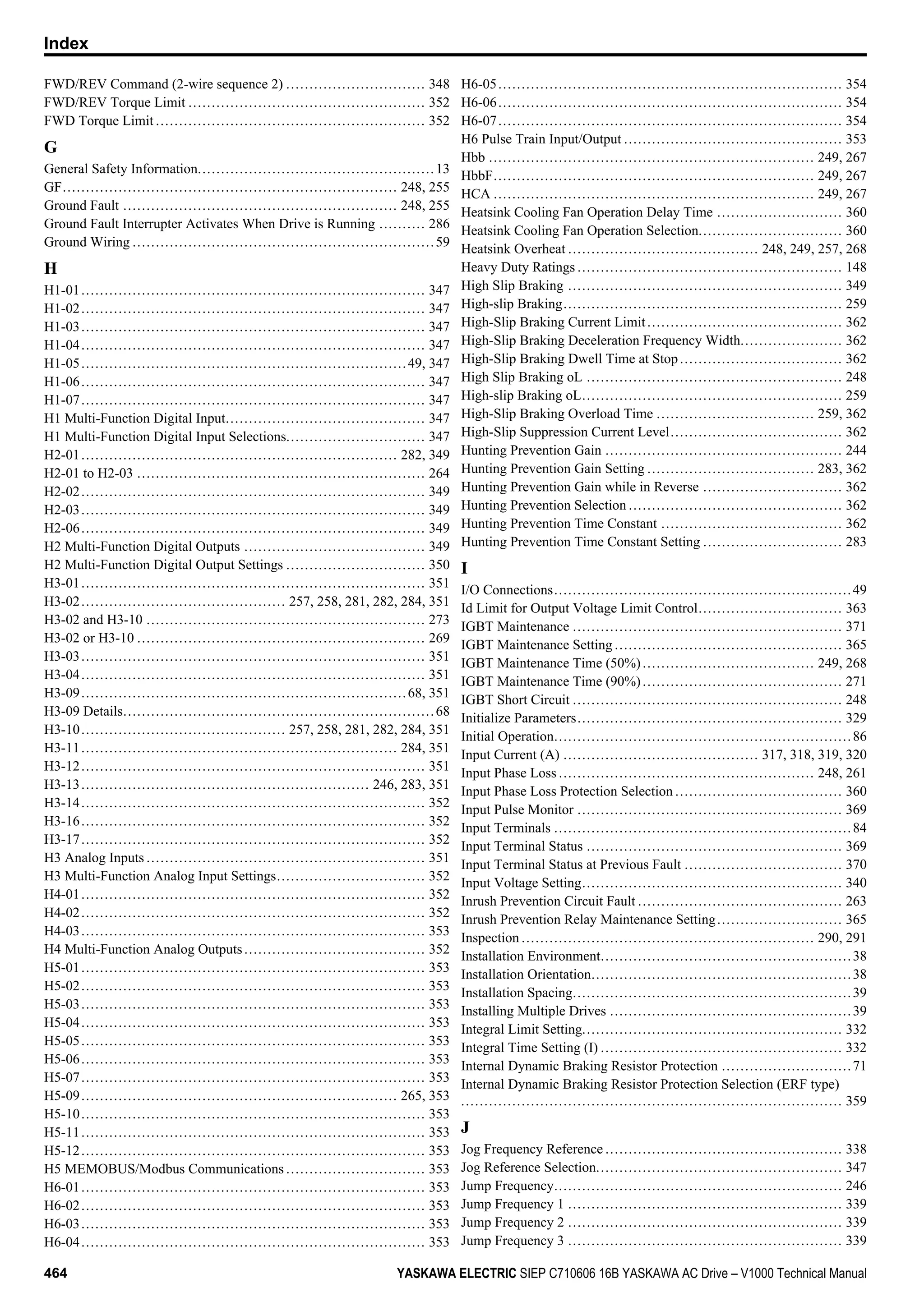
![n E4-03: Motor 2 Rated No-Load Current
Set E4-03 to the motor no-load current at rated voltage and rated frequency. If Rotational Auto-Tuning completes
successfully, this value is automatically calculated. If Auto-Tuning can not be performed contact the motor manufacturer
for information about the no-load current.
No. Parameter Name Setting Range Default
E4-03 Motor 2 Rated No-Load Current 0 to [E4-01]
Depending on
o2-04
Note: The resolution of E4-03 depends on the rated output power of the drive. If a drive is set up for 7.5 kW and lower rated output power
(ND or HD rating) the value will have two decimal places. It will have one decimal place if a drive is set up for 11 kW and higher.
n E4-04: Motor 2 Motor Poles
Set the pole number of motor 2 to E4-04. During Auto-Tuning the value must entered to parameter T1-06. If Auto-Tuning
completes successfully, the entered value will automatically be saved to E4-04.
No. Parameter Name Setting Range Default
E4-04 Motor 2 Motor Poles 2 to 48 4
n E4-05: Motor 2 Line-to-Line Resistance
Sets the line-to-line resistance of motor 2 stator winding. If the Auto-tuning completes successfully, this value is
automatically calculated. Remember this value must be entered as line-line and not line-neutral.
No. Parameter Name Setting Range Default
E4-05 Motor 2 Line-to-Line Resistance 0.000 to 65.000 Ω
Depending on
o2-04
Note: The setting range is 0.00 to 130.00 when using a drive capacity of 0.2 kW or less.
Refer to E2-05: Motor Line-to-Line Resistance on page 164 to manually enter this parameter setting.
n E4-06: Motor 2 Leakage Inductance
Sets the voltage drop due to motor leakage inductance of motor 2. The value is set as a percentage of the rated voltage.
No. Parameter Name Setting Range Default
E4-06 Motor 2 Leakage Inductance 0.0 to 40.0%
Depending on
o2-04
n E4-07: Motor 2 Motor Iron-Core Saturation Coefficient 1
Sets the motor 2 iron saturation coefficient at 50% of magnetic flux. This value is automatically set during Rotational
Auto-Tuning.
No. Parameter Name Setting Range Default
E4-07 Motor 2 Motor Iron-Core Saturation Coefficient 1 0.00 to 0.50 0.50
n E4-08: Motor 2 Motor Iron-Core Saturation Coefficient 2
Sets the motor iron saturation coefficient at 75% of magnetic flux. This value is automatically set during Rotational Auto-
Tuning.
No. Parameter Name Setting Range Default
E4-08 Motor 2 Motor Iron-Core Saturation Coefficient 2 [E4-07] to 0.75 0.75
n E4-09: Motor 2 Mechanical Loss
Sets the motor mechanical loss as a percentage of motor rated power (kW).
No. Parameter Name Setting Range Default
E4-09 Motor 2 Mechanical Loss 0.00 to 10.0% 0.0%
This parameter seldom needs to be changed, but may need to be adjusted in the following circumstances:
• When there is a large amount of torque loss due to motor bearing friction.
• When there is a large amount of torque loss in a fan or pump application.
5.5 E: Motor Parameters
YASKAWA ELECTRIC SIEP C710606 16B YASKAWA AC Drive – V1000 Technical Manual 167
5
ParameterDetails](https://image.slidesharecdn.com/yaskawav1000instuctionmanuelinenglish-160910020601/75/Yaskawa-V1000-Instuction-Manuel-167-2048.jpg)

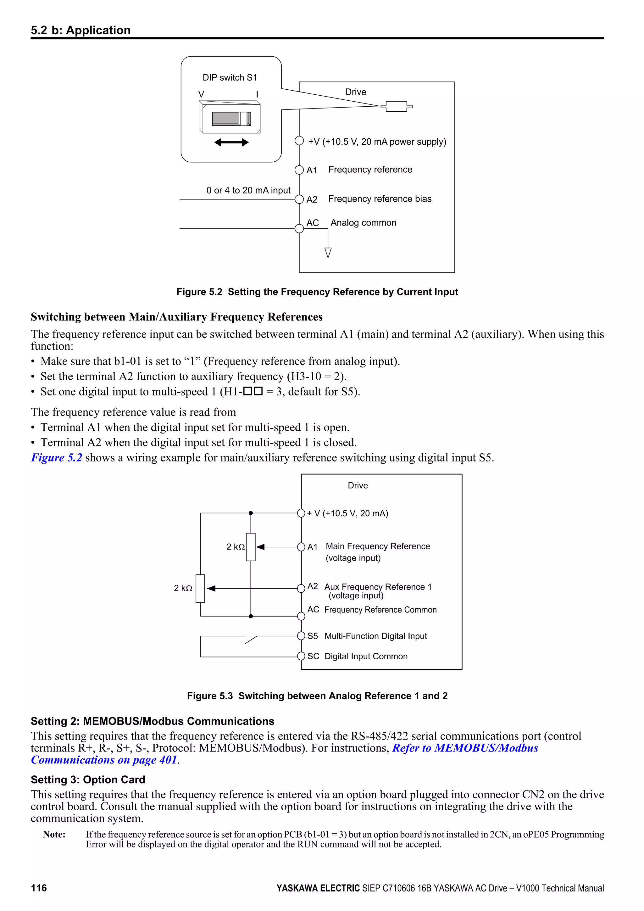
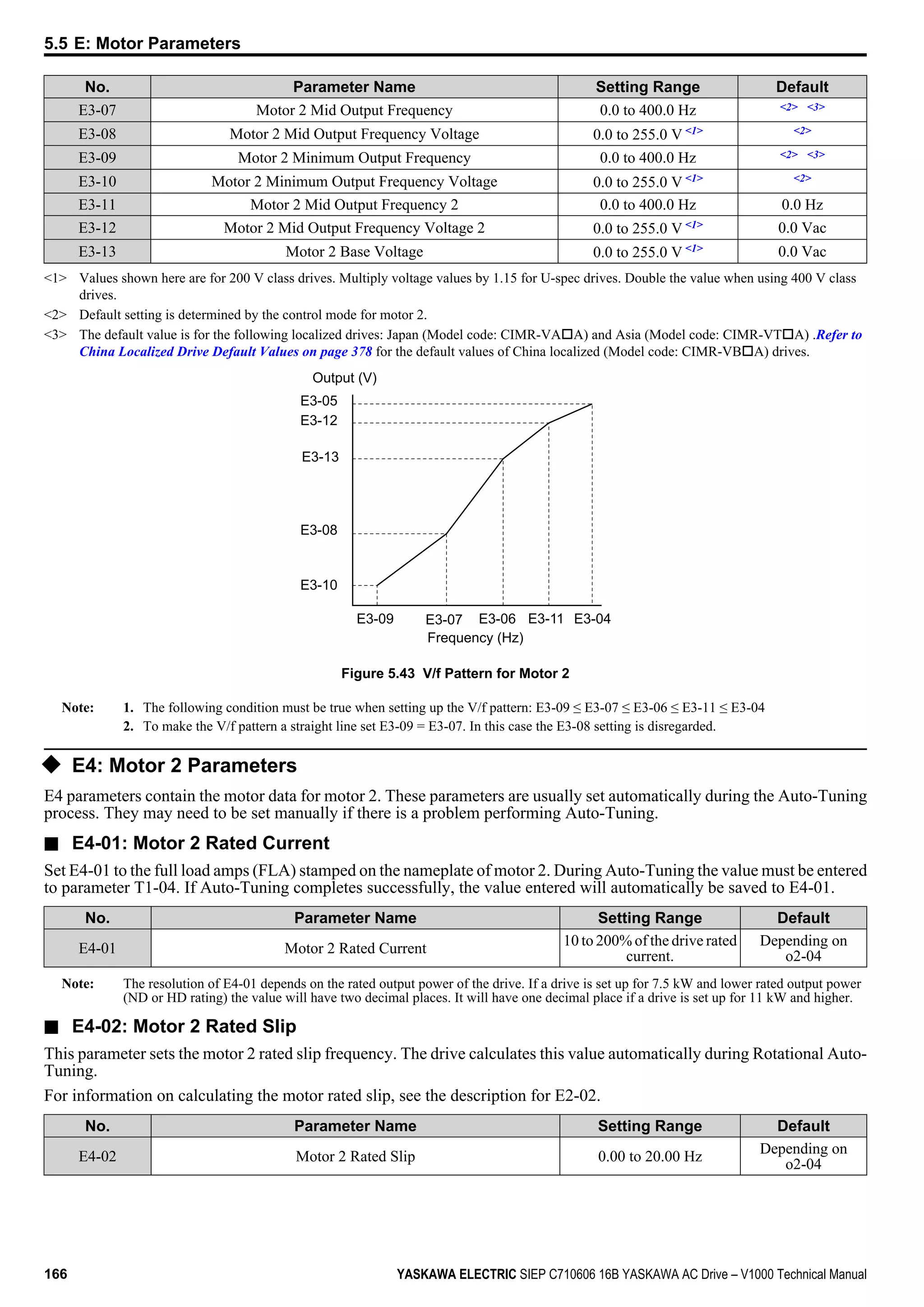
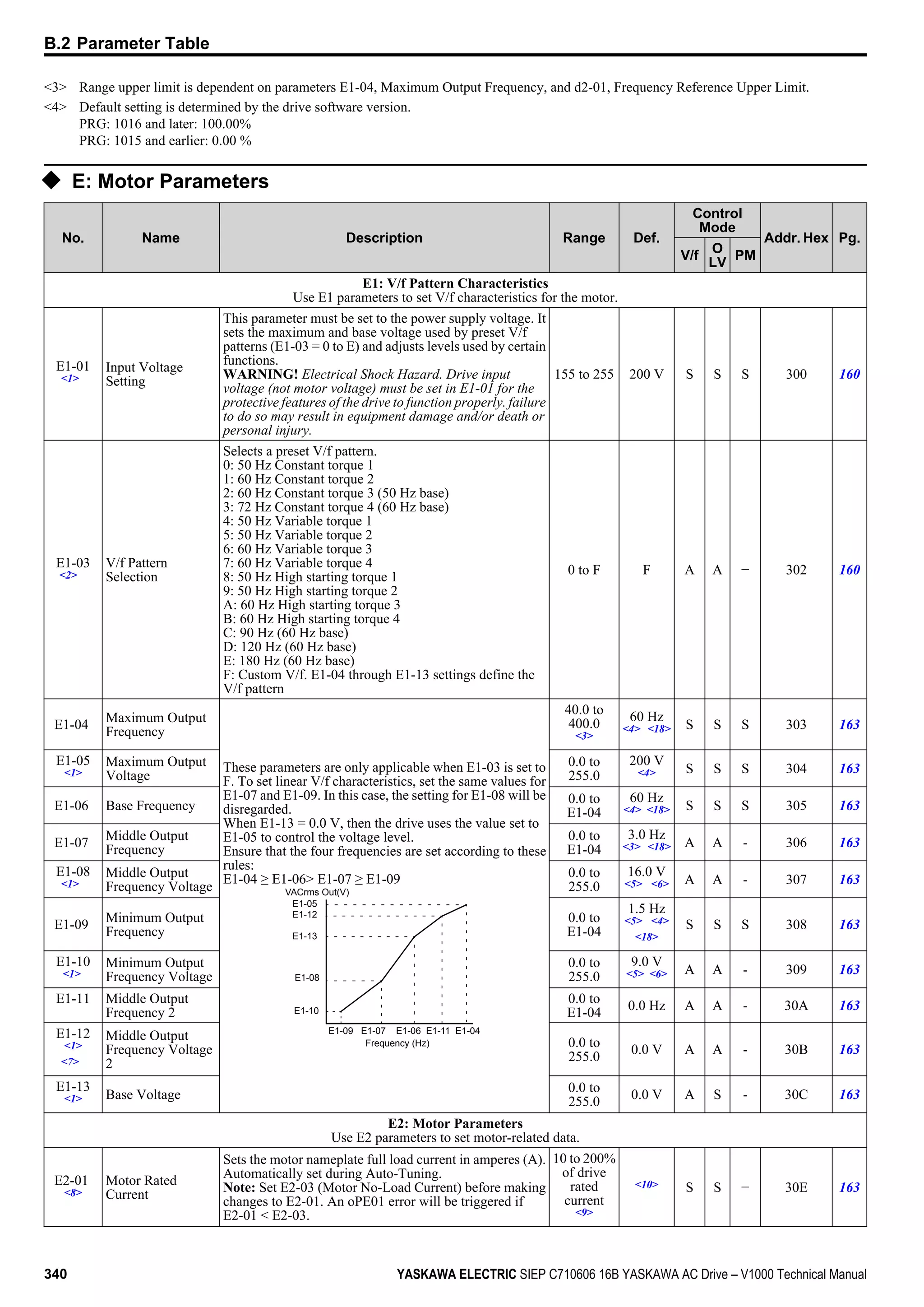
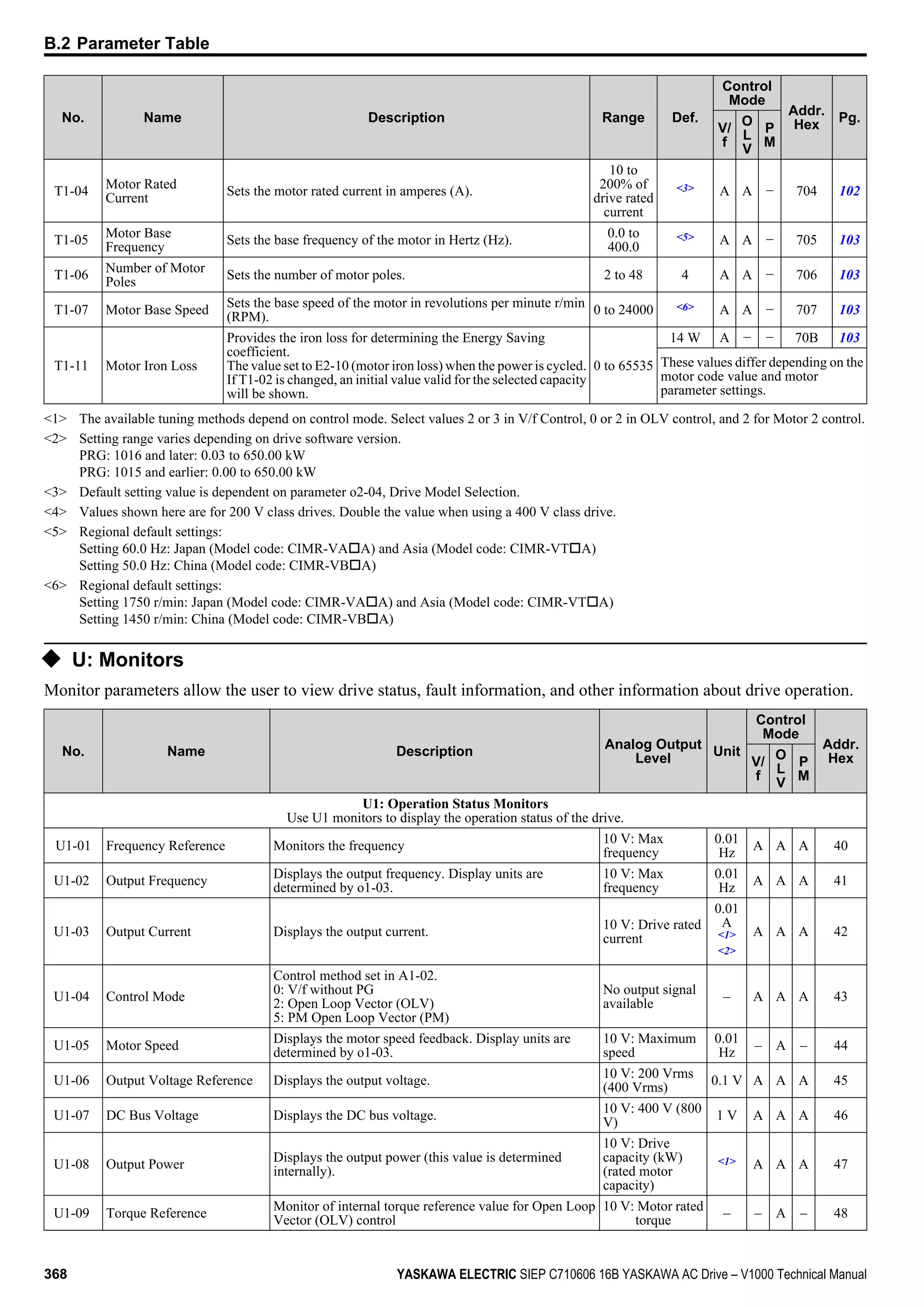
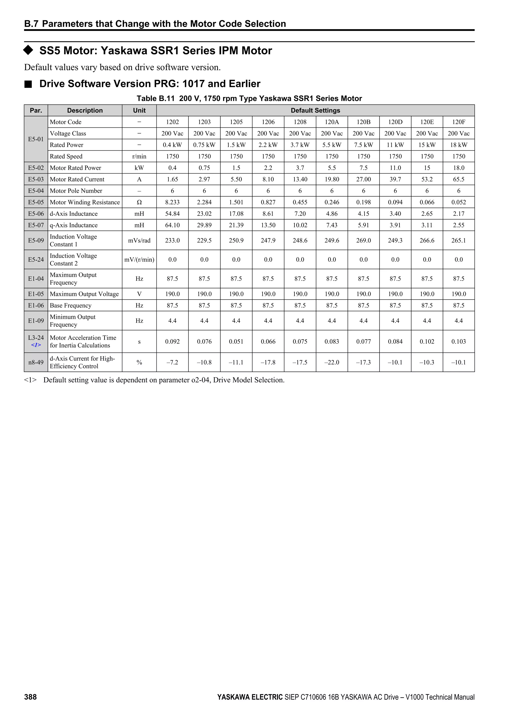
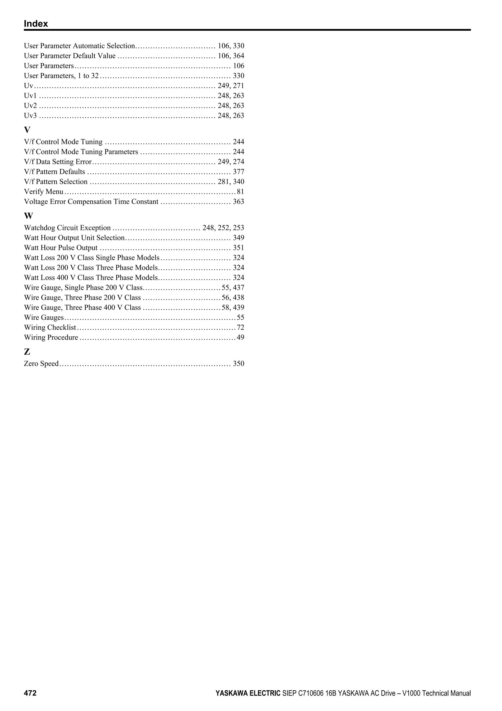
![n E5-09: Motor Induction Voltage Constant 1 (PM OLV)
Set the induced phase peak voltage in units of 0.1 mV/(rad/s) [electrical angle]. Set this parameter when using an SSR1
series IPM motor with derated torque or an SST4 series motor with constant torque.
When E5-01 is set to “FFFF” use either E5-09 or E5-24 for setting the voltage constant.
No. Parameter Name Setting Range Default
E5-09 Motor Induction Voltage Constant 1 0.0 to 2000.0 mV/(rad/s)
Depending on
E5-01
Note: 1. Ensure that E5-24 = 0 when setting parameter E5-09. An alarm will be triggered, however, if both E5-09 and E5-24 are set 0, or if
neither parameter is set to 0.
2. This parameter is not reset when the drive is initialized using A1-03.
n E5-24: Motor Induction Voltage Parameter 2 (PM OLV)
Set the induced phase-to-phase rms voltage in units of 0.1 mV/(r/min) [mechanical angle]. Set this parameter to 0 when
using an SMRA Series SPM Motor.
When E5-01 is set to “FFFF” use either E5-09 or E5-24 for setting the voltage constant.
No. Parameter Name Setting Range Default
E5-24 Motor Induction Voltage Parameter 2 (PM OLV) <1> Depending on
E5-01
<1> Range depends on the drive software version.
PRG: 1018 and later: 0.0 to 6500.0 mV/(r/min)
PRG: 1017 and earlier: 0.0 to 2000.0 mV/(r/min)
Note: 1. If E5-03 is not set to 0, then setting both E5-09 and E5-24 to 0, or setting neither E5-09 nor E5-24 to 0, will trigger an oPE08 error.
However, if E5-03 is set to 0, setting both E5-09 and E5-24 to 0 will not trigger the error.
2. This parameter is not reset when the drive is initialized using A1-03.
3. The values for the electrical and mechanical angle should be set using the same units specified by the manufacturer of the motor.
5.5 E: Motor Parameters
170 YASKAWA ELECTRIC SIEP C710606 16B YASKAWA AC Drive – V1000 Technical Manual](https://image.slidesharecdn.com/yaskawav1000instuctionmanuelinenglish-160910020601/75/Yaskawa-V1000-Instuction-Manuel-170-2048.jpg)


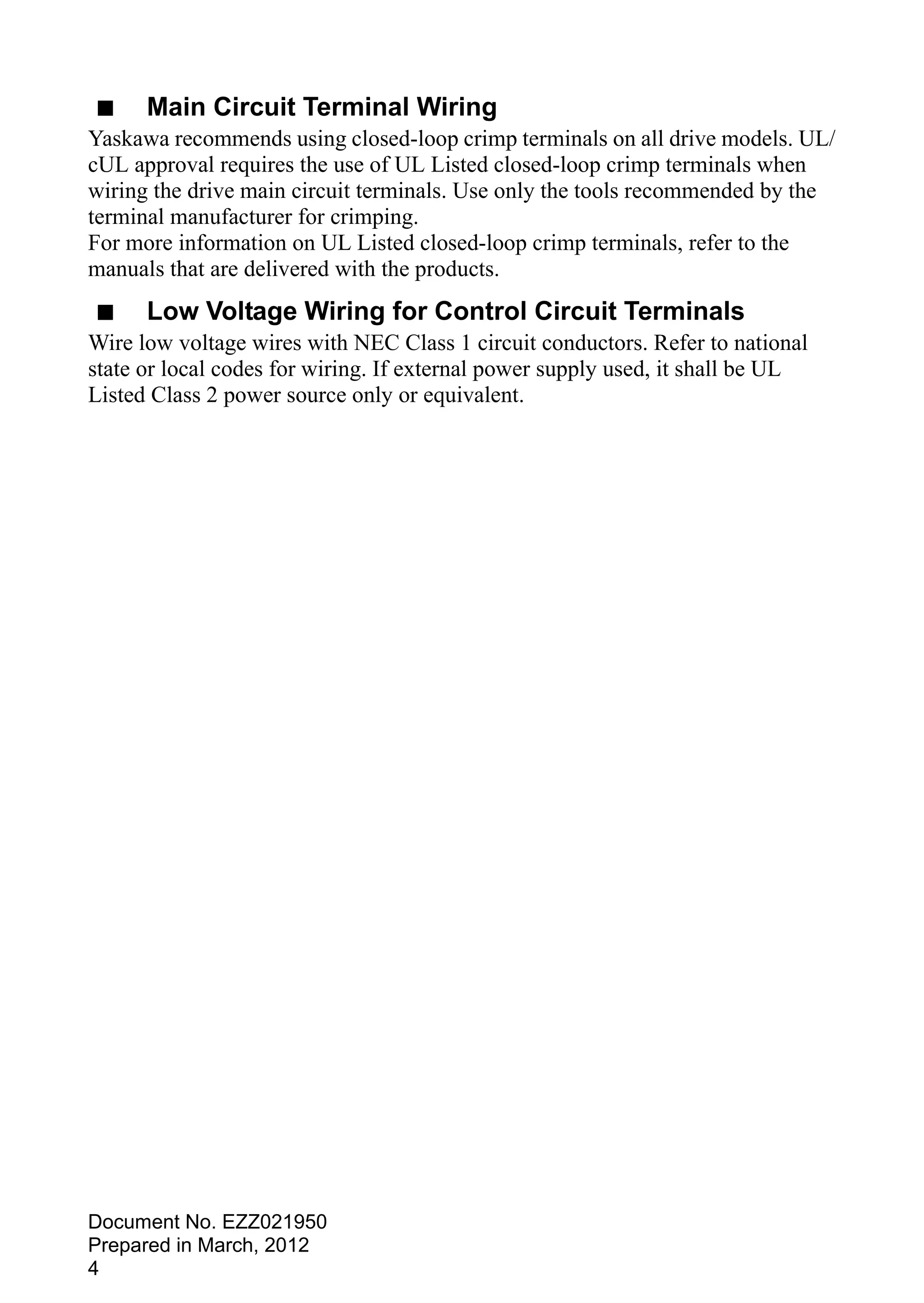
![• Small reductions in the acceleration gain can also help solve problems with overvoltage and overcurrent.
• Decreasing this setting too much can result in a slow DC bus voltage control response and may also lengthen deceleration
times beyond optimal levels.
Adjustment for Overvoltage Suppression
• Increase this setting in steps of 0.1 if overvoltage occurs as a result of a regenerative load when overvoltage suppression
is enabled (L3-11 = 1).
• If there is a fairly large speed ripple when overvoltage suppression is enabled, then decrease L3-21 in steps of 0.05.
n L3-24: Motor Acceleration Time for Inertia Calculations
Sets the time it takes to accelerate the motor from stop to the maximum speed at motor rated torque. This parameter should
be set when using KEB Ride-Thru 2, Intelligent Stall Prevention during deceleration (L2-04 = 2), or the overvoltage
suppression function (L3-11 = 1).
No. Name Setting Range Default
L3-24 Motor Acceleration Time for Inertia Calculations 0.001 to 10.000
Determined by o2-04, E2-11, and
E5-01 <1>
<1> Parameter L3-24 is defaulted for a Yaskawa standard 4-pole motor. During Auto-Tuning, L3-24 will be initialized to a Yaskawa standard 4-
pole motor if parameter E2-11 is changed. This value also changes based on the motor code set to E5-01 when using the Open Loop Vector
Control Mode for PM motors.
Calculations are made as follows:
L3-24 =
2 J [kgm2
] n [r/min]
60 T [Nm]
rated
rated
The rated torque can be calculated as follows:
60 P [kW] 103
2 n [r/min]
T [Nm] =
Motor
rated
rated
n L3-25: Load Inertia Ratio
Determines the ratio between the rotor inertia and the load. Set this parameter when using KEB Ride-Thru 2, Intelligent
Stall Prevention during deceleration (L3-04 = 2), or the overvoltage suppression function (L3-11 = 1).
No. Name Setting Range Default
L3-25 Load Inertia Ratio 0.0 to 1000.0 1.0
When set incorrectly, a fairly large current ripple can result during KEB Ride-Thru 2 and overvoltage suppression (L3-11
= 1) or other faults such as ov, Uv1, and oC may occur.
Parameter L3-25 can be calculated by:
L3-25 =
Machine Inertia
Motor Inertia
u L4: Speed Agree/Frequency Reference Loss Detection
These parameters set up the speed agree and speed detection functions which can be assigned to the multi-function output
terminals.
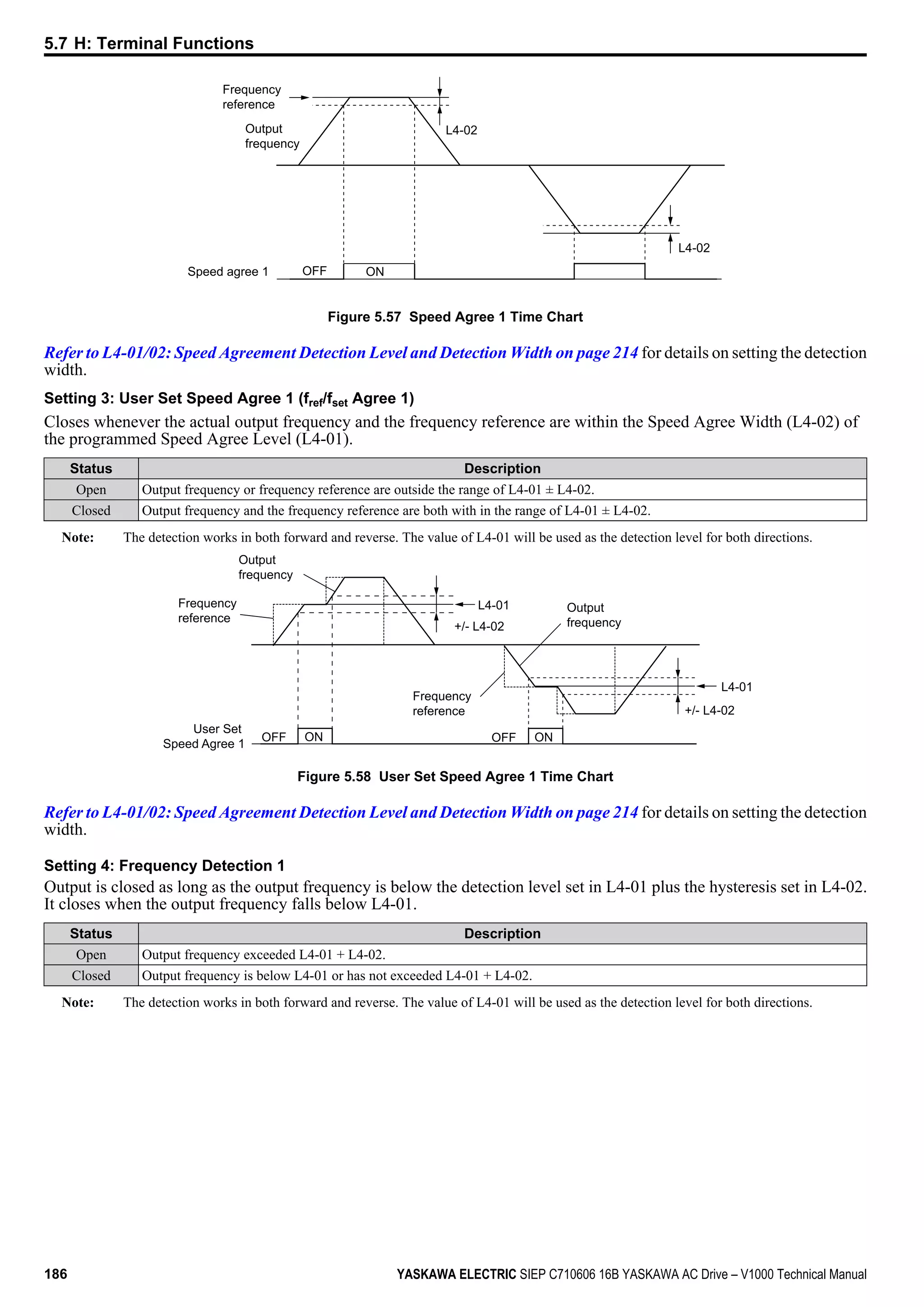
n L4-01/02: Speed Agreement Detection Level and Detection Width
Parameter L4-01 sets the detection level for the digital output functions “Speed Agree 1”, “User Set Speed Agree 1”,
“Frequency Detection 1”, and “Frequency Detection 2”.
Parameter L4-02 sets the hysteresis level for these functions.
No. Name Setting Range Default
L4-01 Speed Agreement Detection Level 0.0 to 400.0 Hz 0.0 Hz
L4-02 Speed Agreement Detection Width 0.0 to 20.0 Hz 2.0 Hz
Refer to H2-01 to H2-03: Terminal MA/MB/MC, P1/PC and P2/PC Function Selection on page 184, Settings 2, 3, 4,
and 5.
n L4-03/04: Speed Agreement Detection Level and Detection Width (+/-)
Parameter L4-03 sets the detection level for the digital output functions “Speed Agree 2”, “User Set Speed Agree 2”,
“Frequency Detection 3”, and “Frequency Detection 4”.
5.8 L: Protection Functions
214 YASKAWA ELECTRIC SIEP C710606 16B YASKAWA AC Drive – V1000 Technical Manual](https://image.slidesharecdn.com/yaskawav1000instuctionmanuelinenglish-160910020601/75/Yaskawa-V1000-Instuction-Manuel-214-2048.jpg)


![n n8-87: Output Voltage Limit Selection
Note: Parameter available in drive software versions PRG: 1018 and later.
Determines the method of the output voltage limit. Use the feed-forward method if oscillation occurs in the constant output
range. There is normally no need to change this parameter from its default value.
No. Name Setting Range Default
n8-87 Output Voltage Limit Selection 0 or 1 0
Setting 0: Feedback Method
Setting 1: Feed-Forward Method
n n8-88: Output Voltage Limit Switching Current Level
Note: Parameter available in drive software versions PRG: 1018 and later.
Sets the current level to switch the output voltage limit sequence. Set as a percentage of the motor rated current (E5-03).
There is normally no need to change this parameter from its default value.
No. Name Setting Range Default
n8-88 Output Voltage Limit Switching Current Level 0 to 400% 400%
n n8-89: Output Voltage Limit Switching Current Hysteresis Width
Note: Parameter available in drive software versions PRG: 1018 and later.
Determines the hysteresis of the current level to switch the output voltage limit sequence. Set as a percentage of the motor
rated current (E5-03).
No. Name Setting Range Default
n8-89 Output Voltage Limit Switching Current Hysteresis Width 0 to [n8-88] 3%
n n8-90: Output Voltage Limit Switching Speed
Note: Parameter available in drive software versions PRG: 1018 and later.
Sets the speed level to switch the output voltage limit sequence. Set as a percentage of the maximum output frequency
(E1-04).
No. Name Setting Range Default
n8-90 Output Voltage Limit Switching Speed 0 to 200% 200%
n n8-91: Id Limit for Output Voltage Limit Control
Note: Parameter available in drive software versions PRG: 1018 and later.
Sets the amount of pull-in current that flows through the motor while operating at constant speed. Set as a percentage of
the motor rated current (E5-03). Increase this setting if hunting occurs at constant speed.
No. Name Setting Range Default
n8-91 Id Limit for Output Voltage Limit Control -200 to 0% -50%
5.9 n: Special Adjustments
232 YASKAWA ELECTRIC SIEP C710606 16B YASKAWA AC Drive – V1000 Technical Manual](https://image.slidesharecdn.com/yaskawav1000instuctionmanuelinenglish-160910020601/75/Yaskawa-V1000-Instuction-Manuel-232-2048.jpg)


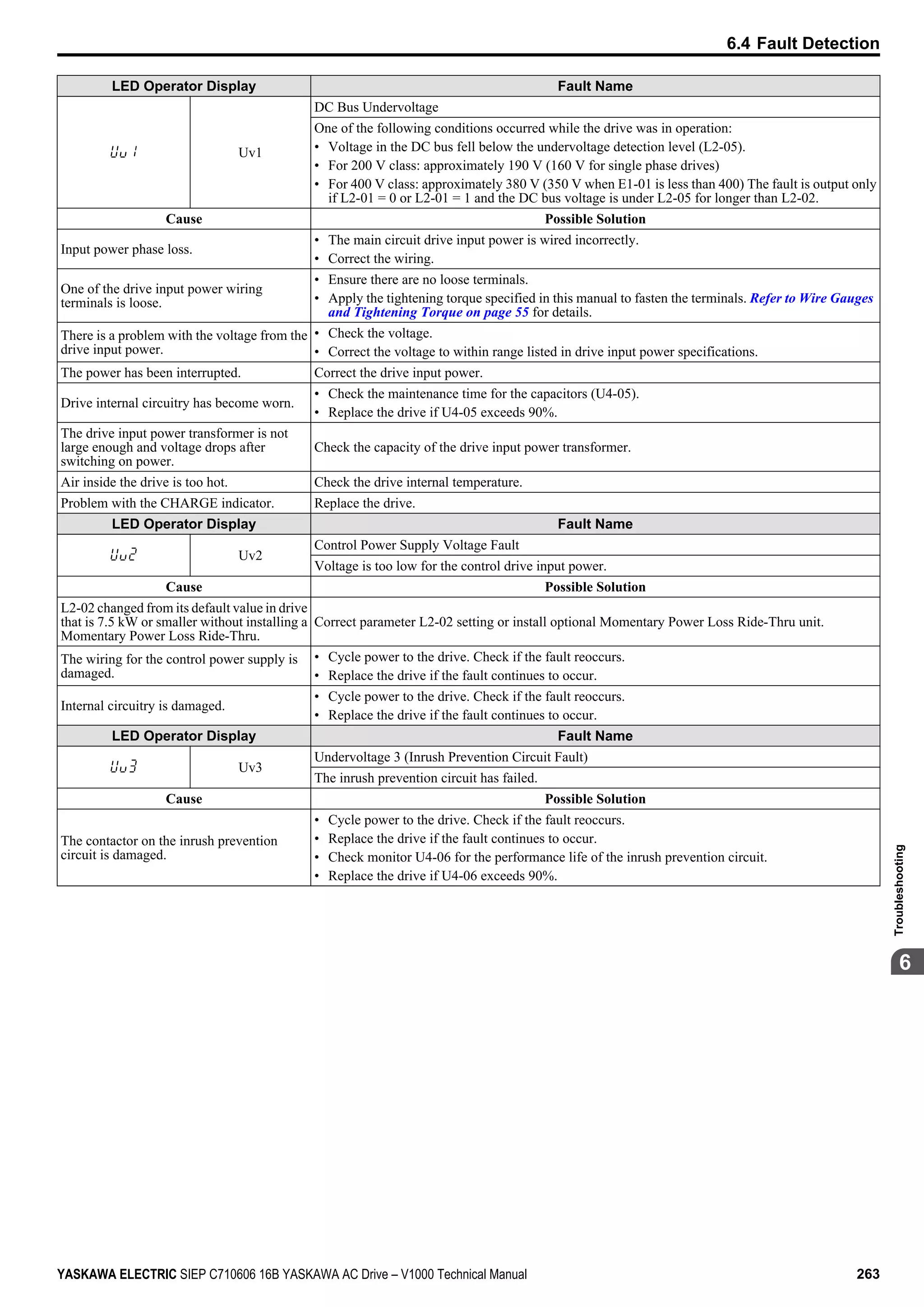


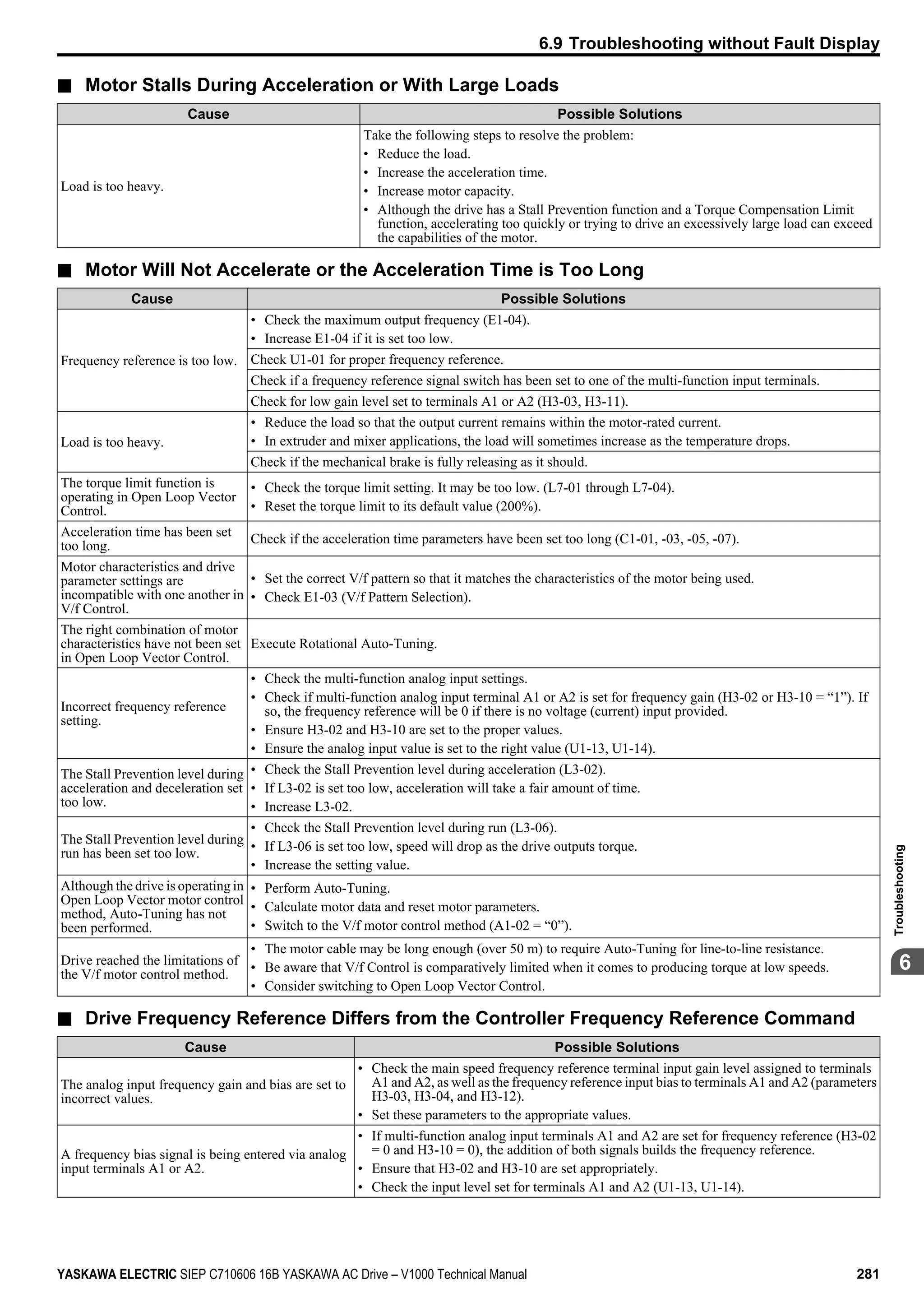

![n Noise From Drive or Output Lines When the Drive is Powered On
Cause Possible Solutions
Relay switching in the drive
generates excessive noise.
• Lower the carrier frequency (C6-02).
• Install a noise filter on the input side of drive input power.
• Install a noise filter on the output side of the drive.
• Place the wiring inside a metal conduit to shield it from switching noise.
• Ground the drive and motor properly.
• Separate the main circuit wiring and the control lines.
n Ground Fault Circuit Interrupter (GFCI) Trips During Run
Cause Possible Solutions
Excessive leakage current trips
MCCB.
• Increase the GFCI sensitivity or use GFCI with a higher threshold.
• Lower the carrier frequency (C6-02).
• Reduce the length of the cable used between the drive and the motor.
• Install a noise filter or reactor on the output side of the drive.
n Connected Machinery Vibrates When Motor Rotates
Excessive Motor Oscillation and Erratic Rotation
Cause Possible Solution
Poor balance between motor phases. Check drive input power voltage to ensure that it provides stable power.
Unexpected Noise from Connected Machinery
Cause Possible Solutions
The carrier frequency is at the resonant frequency of
the connected machinery.
Adjust the carrier frequency using parameters C6-02 through C6-05.
The drive output frequency is the same as the
resonant frequency of the connected machinery.
• Adjust the parameters used for the Jump Frequency function (d3-01 through d3-04) to skip
the problem-causing bandwidth.
• Place the motor on a rubber pad to reduce vibration.
Note: The drive may have trouble assessing the status of the load due to white noise generated when using Swing PWM (C6-02 = 7 to A).
n Oscillation or Hunting
Cause Possible Solutions
Insufficient tuning in Open Loop Vector Control
Adjust the following parameters in the order listed.
An increase in gain should be followed with an increase in the primary delay time constant.
• C4-02 (Torque Compensation Primary Delay Time)
• n2-01 (Speed Feedback Detection Control [AFR] Time Constant 1)
• C3-02 (Slip Compensation Primary Delay Time)
The response for torque compensation and slip compensation will drop as the time constant
is increased.
Auto-Tuning has not yet been performed (required
for Open Loop Vector Control).
Perform Auto-Tuning.
Set motor parameters after calculating the proper values.
Change the motor control method to V/f Control (A1-02 = “0”).
Insufficient tuning in V/f Control.
Reduce the gain.
• n1-02 (Hunting Prevention Gain Setting)
• n1-03 (Hunting Prevention Time Constant Setting)
Gain is too low when using PID control. Check the period of oscillation and adjust P, I, and D settings accordingly.
The frequency reference is assigned to an external
source and the signal is noisy.
• Ensure that noise is not affecting the signal lines.
• Separate main circuit wiring and control circuit wiring.
• Use twisted-pair cables or shielded wiring for the control circuit.
• Increase the analog input time filter constant (H3-13).
The cable between the drive and motor is too long.
• Perform Auto-Tuning.
• Reduce the length of the cable.
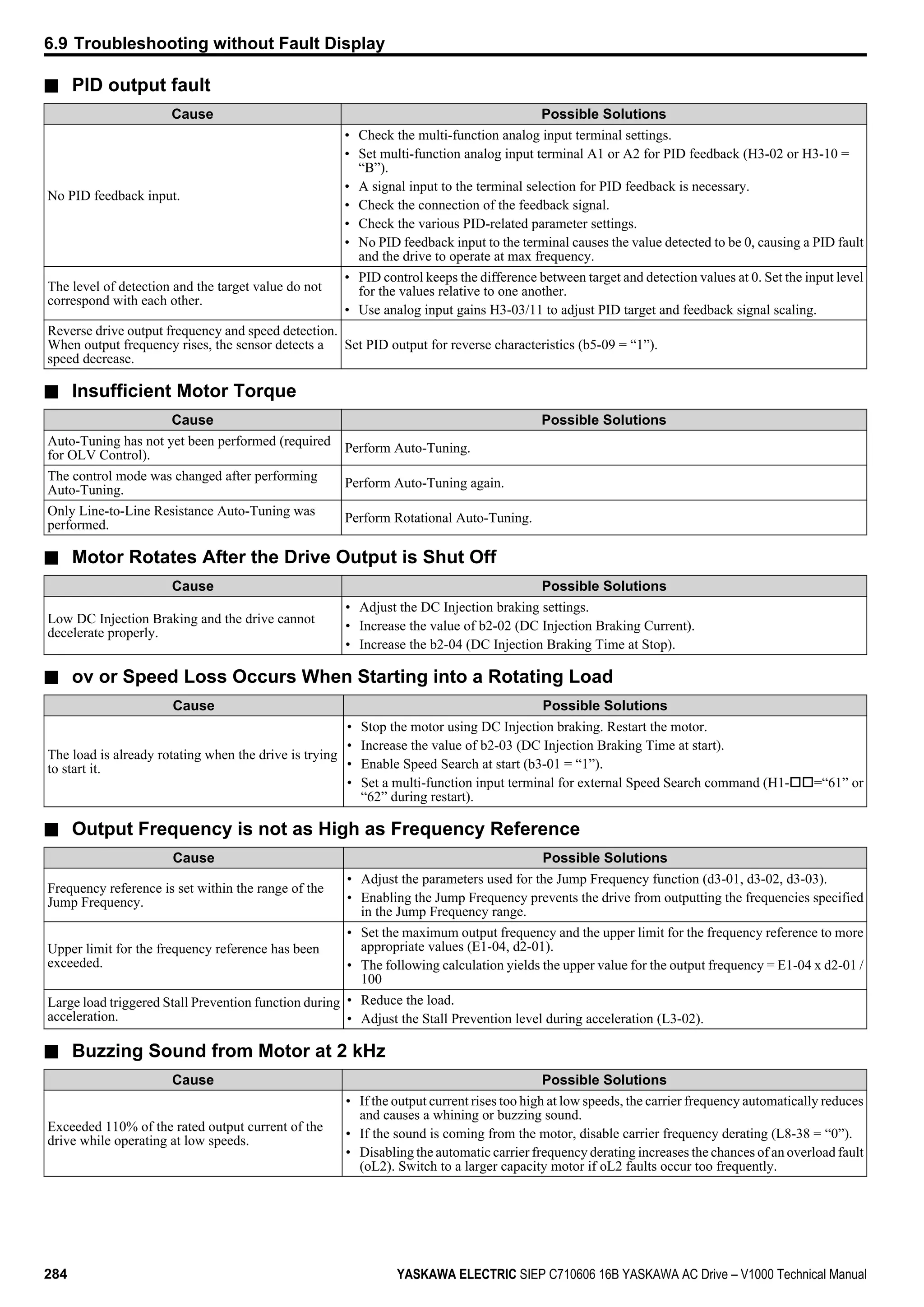
6.9 Troubleshooting without Fault Display
YASKAWA ELECTRIC SIEP C710606 16B YASKAWA AC Drive – V1000 Technical Manual 283
6
Troubleshooting](https://image.slidesharecdn.com/yaskawav1000instuctionmanuelinenglish-160910020601/75/Yaskawa-V1000-Instuction-Manuel-283-2048.jpg)


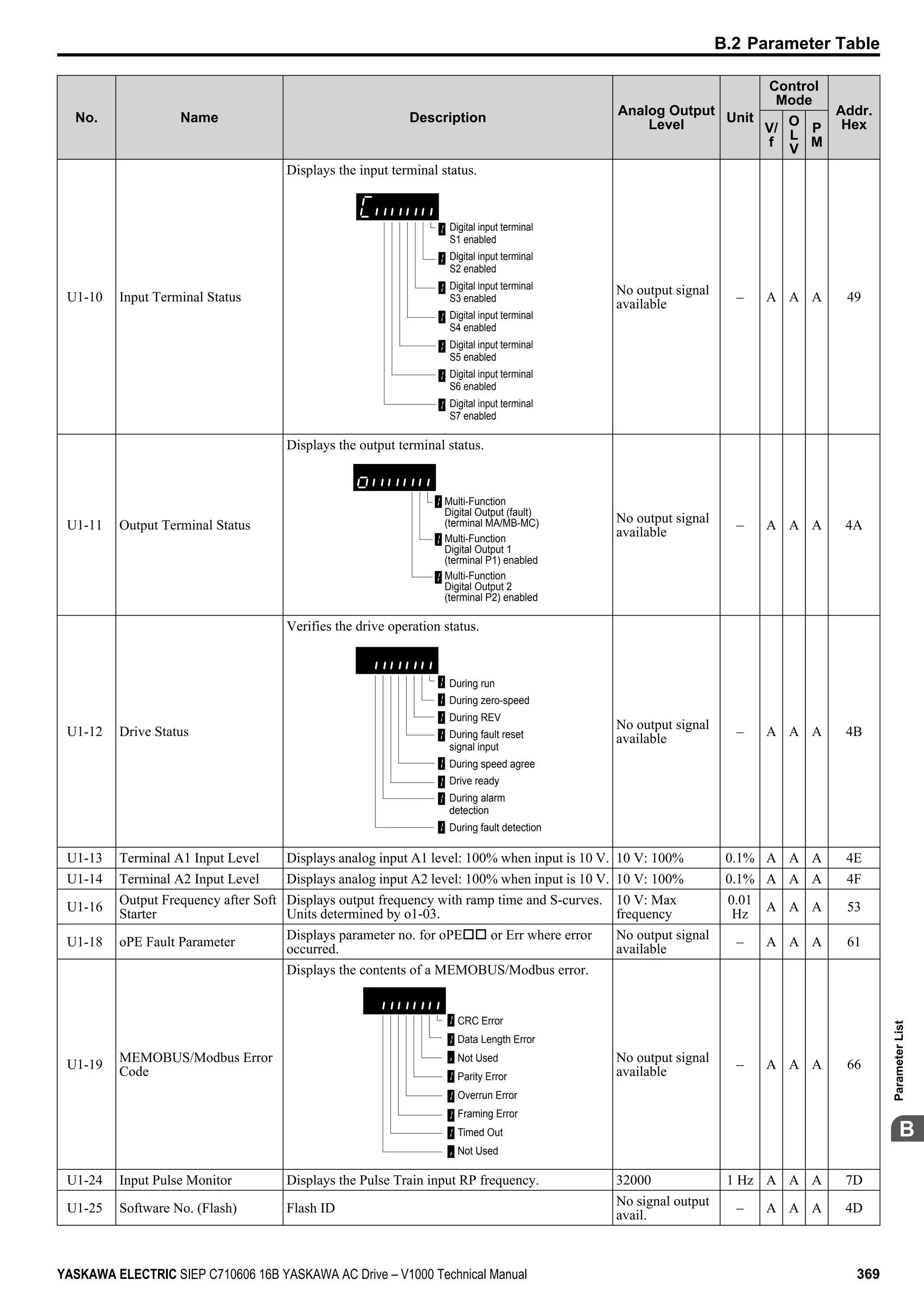
![No. Name Description Range Def.
Control
Mode
Addr. Hex Pg.
V/f
O
LV
PM
E5-03
<2>
Motor Rated
Current
Sets the motor rated current in amps.
10 to 200%
of drive
rated
current
<9>
<16> − − S 32B 169
E5-04
<2> Motor Poles Sets the number of motor poles. 2 to 48 <4> − − S 32C 169
E5-05
<2> Motor Resistance
Set the resistance for each motor phase in units of
0.001 Ω.
0.000 to
65.000
<4> − − S 32D 169
E5-06
<2>
Motor d Axis
Inductance
Sets the d axis inductance in units of 0.01 mH.
0.00 to
300.00
<4> − − S 32E 169
E5-07
<2>
Motor q Axis
Inductance
Sets the q axis inductance in units of 0.01 mH.
0.00 to
600.00
<4> − − S 32F 169
E5-09
<2>
Motor Induction
Voltage Constant 1
Set the induced phase peak voltage in units of 0.1 mV (rad/
s) [electrical angle].
Set this parameter when using a Yaskawa SSR1 series PM
motor with derate torque, or a Yaskawa SST4 series motor
with constant torque.
When setting this parameter, E5-24 should be set to 0. An
alarm will be triggered if both E5-09 and E5-24 are set to
0, or if neither parameter is set to 0.
0.0 to
2000.0
<4> − − S 331 170
E5-24
<2>
Motor Induction
Voltage Constant 2
Set the induced phase-to-phase rms voltage in units of 0.1
mV/(r/min) [mechanical angle].
Set this parameter when using a Yaskawa SMRA Series
SPM Motor.
When setting this parameter, E5-09 should be set to 0. An
alarm will be triggered if both E5-09 and E5-24 are set to
0, or if neither parameter is set to 0.
If E5-03 (Motor Rated Current) is set to 0, however, then
an alarm will not be triggered when both E5-09 and E5-24
are set to 0.
<17> <4> − − S 353 170
<1> Values shown here are for 200 V class drives. Double the value when using a 400 V class drive.
<2> Parameter setting value is not reset to the default value during drive initialization, A1-03 = 1110, 2220, 3330.
<3> Range upper limit is dependent on parameter E4-01 Motor 2 Rated Current.
<4> Default setting value is dependent on parameter E5-01, Motor Code Selection.
<5> Default setting value is dependent on parameter A1-02, Control Method Selection. The value shown is for A1-02 = 0-V/f Control.
<6> Default setting value is dependent on parameter o2-04, Drive Model Selection.
<7> Parameter ignored when E1-11, Motor 1 Mid Output Frequency 2, and E1-12, Motor 1 Mid Output Frequency Voltage 2, are set to 0.0.
<8> When setting motor parameters, the motor rated current must be set to a value greater than the motor no-load current (E2-01 > E2-03).
<9> Setting units for this parameter are determined by o2-04, Drive Model Selection. Less than 11 kW: 2 decimal points, 11 kW and above: 1
decimal point.
<10> Default setting value is dependent on parameter o2-04, Drive Model Selection and C6-01, Drive Duty Selection.
<11> Setting range becomes 0.00 to 130.00 for drives 0.2 kW and smaller.
<12> Default setting depends on the control mode for motor 2 set in parameter E3-01. The given value is for V/f Control.
<13> Parameter ignored when E3-11, Motor 2 Mid Output Frequency 2, and E3-12, Motor 2 Mid Output Frequency Voltage 2, are set to 0.
<14> Parameter can be changed during Run.
<15> If using a Yaskawa SMRA Series SPM Motor, the default setting is 1800 r/min.
<16> Default setting value is dependent on parameter A1-06. This setting value is 0 when A1-06 = 0, and 1 when A1-06 ≠ 0.
<17> Default setting is determined by drive software version.
PRG: 1018 and later: 0.0 to 6500.0 mV/(r/min)
PRG: 1017 and earlier: 0.0 to 2000.0 mV/(r/min)
<18> The default value is for the following localized drives: Japan (Model code: CIMR-VAoA) and Asia (Model code: CIMR-VToA) .Refer to
China Localized Drive Default Values on page 378 for the default values of China localized (Model code: CIMR-VBoA) drives.
u F: Options
F parameters are used to program the drive for PG feedback and to function with option cards.
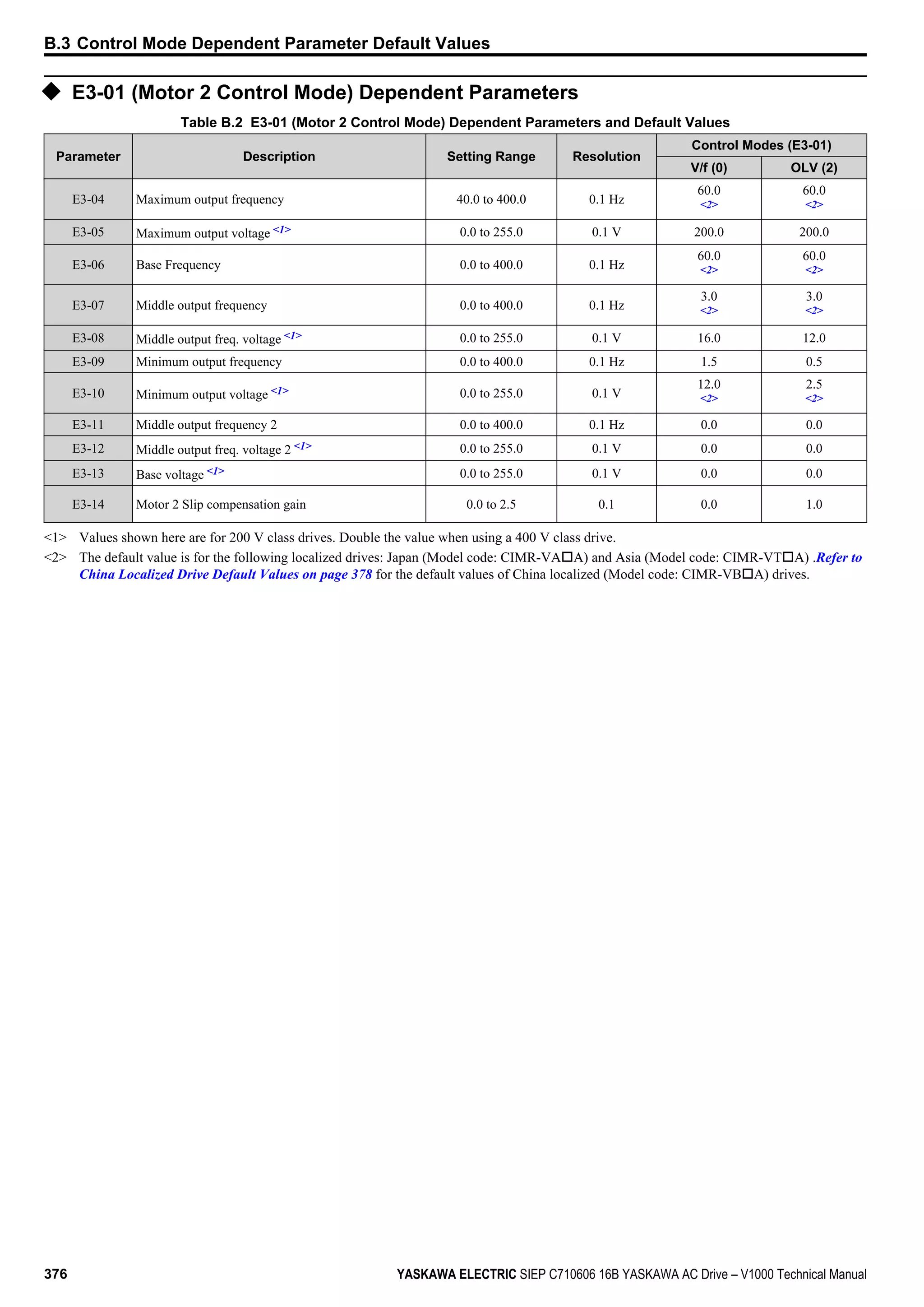
B.2 Parameter Table
YASKAWA ELECTRIC SIEP C710606 16B YASKAWA AC Drive – V1000 Technical Manual 343
B
ParameterList](https://image.slidesharecdn.com/yaskawav1000instuctionmanuelinenglish-160910020601/75/Yaskawa-V1000-Instuction-Manuel-343-2048.jpg)


![No. Name Description Range Def.
Control
Mode
Addr.
Hex
Pg.
V/
f
O
L
V
P
M
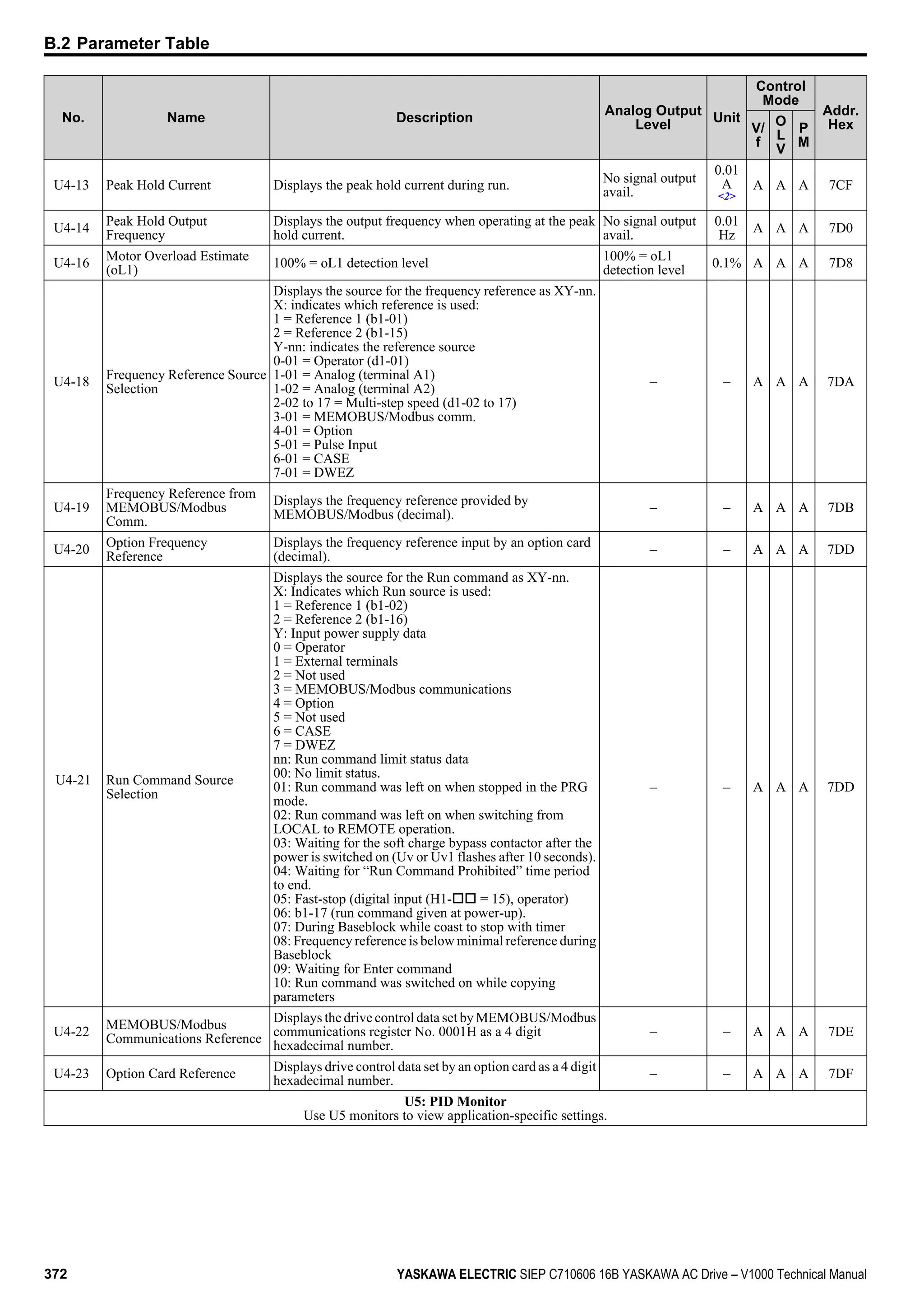
n6-01
Line-to-Line Motor
Resistance Online Tuning
Tunes the line-to-line motor resistance continuously during
operation.
0: Disabled
1: Enabled
0, 1 1 − A − 570 229
n8: Permanent Magnet (PM) Motor Control
Use n8 parameters to control the PM motor control.
n8-45
Speed Feedback Detection
Control Gain
Sets the gain for internal speed feedback detection control.
This parameter does not typically require adjustment.
Increase this setting if hunting occurs.
Decrease to lower the response.
0.00 to
10.00
0.80 − − A 538 230
n8-47
Pull-In Current
Compensation Time
Constant
Sets the time constant to make the pull-in current and actual
current value agree.
Decrease the value if the motor begins to oscillate.
Increase the value if it takes too long for the current reference
to equal the output current.
0.0 to
100.0 s
5.0 s − − A 53A 230
n8-48
<2> Pull-In Current
Defines the amount of current provided to the motor during
no-load operation at a constant speed.
Set as a percentage of the motor rated current. Increase this
setting when hunting occurs while running at a constant
speed.
<3> 30% − − A 53B 230
n8-49
<2>
d-Axis Current for High-
Efficiency Control
Sets the amount of d-Axis current when using Energy Saving
control.
<4> 0% − − A 53C 230
n8-51
Acceleration Pull-In Current
Sets the pull-in current during acceleration as a percentage
of the motor rated current (E5-03). Set to a high value when
more starting torque is needed.
0 to 200% 50% − − A 53E 230
n8-54
Voltage Error Compensation
Time Constant
Sets the time constant for voltage error compensation. Adjust
the value when hunting occurs at low speed.
Increase in steps of 0.1 or disable the compensation by setting
n8-45 to 0 when hunting occurs with sudden load changes or
when oscillations occur at start.
0.00 to
10.00 s
1.00 s − − A 56D 231
n8-55 Load Inertia
Sets the ratio between motor and machine inertia.
0: less than 1:10.
1: between 1:10 to 1:30.
2: between 1:30 to 1:50.
3: higher than 1:50.
0 to 3 0 − − A 56E 231
n8-62
<5> Output Voltage Limit
Sets the limit for the output voltage. Adjustment is normally
needed only if the input voltage is below the n8-62 set value.
In this case set n8-62 to the input voltage.
0.0 to
230.0
200
Vac
− − A 57D 231
n8-63
<6>
Output Voltage Limit Gain
1
Sets the gain used for output voltage limit.
0.00 to
100.00
1.00 – – A 57E 231
n8-65
<7>
Speed Feedback Detection
Control Gain during ov
Suppression
Sets the gain used for internal speed feedback detection
during ov Suppression
0.00 to
10.00
1.50 − − A 65C 231
n8-68
<6> Output Voltage Limit Gain 2 Sets the voltage detection level adjustment gain.
0.50 to
1.50
0.95 – – A 237 231
n8-87
<6>
Output Voltage Limit
Selection
Determines the method of the output voltage limit.
0: Feedback method
1: Feed forward method Use the feed forward method if
oscillation occurs in the constant output range.
0, 1 0 – – A 2BC 232
n8-88
<6>
Output Voltage Limit
Switching Current Level
Sets the current level to switch the output voltage limit
sequence. Set as a percentage of the motor rated current
(E5-03).
0 to 400% 400% – – A 2BD 232
n8-89
<6>
Output Voltage Limit
Switching Current
Hysteresis Width
Determines the hysteresis of the current level to switch the
output voltage limit sequence. Set as a percentage of the
motor rated current (E5-03).
0 to
[n8-88]
3% – – A 2BE 232
n8-90
<6>
Output Voltage Limit
Switching Speed
Sets the speed level to switch the output voltage limit
sequence. Set as a percentage of the maximum output
frequency (E1-04).
0 to 200% 200% – – A 2BF 232
n8-91
<6>
Id Limit for Output Voltage
Limit Control
Sets the amount of pull-in current that flows through the
motor while operating at constant speed. Set as a percentage
of the motor rated current (E5-03). Increase this setting if
hunting occurs at constant speed.
-200 to
0%
-50% – – A 2F7 232
<1> Default setting value is dependent on parameter o2-04, Drive Model Selection.
<2> Parameter can be changed during Run.
<3> Setting range varies depending on drive software version. Software versions PRG: 1018 and later disable pull-in current when n8-48 = 0 and
allow this parameter to be changed during run.
B.2 Parameter Table
YASKAWA ELECTRIC SIEP C710606 16B YASKAWA AC Drive – V1000 Technical Manual 363
B
ParameterList](https://image.slidesharecdn.com/yaskawav1000instuctionmanuelinenglish-160910020601/75/Yaskawa-V1000-Instuction-Manuel-363-2048.jpg)


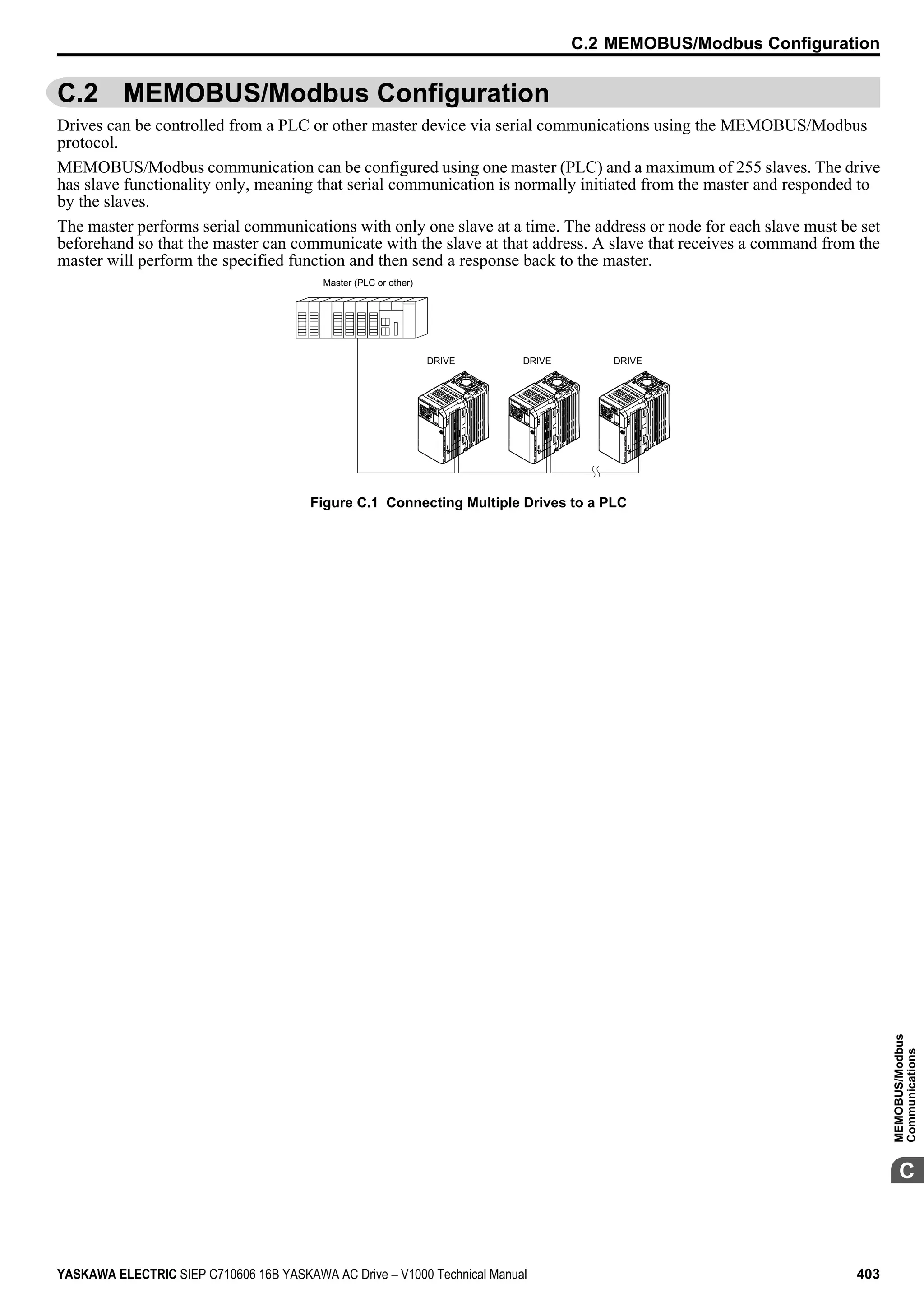
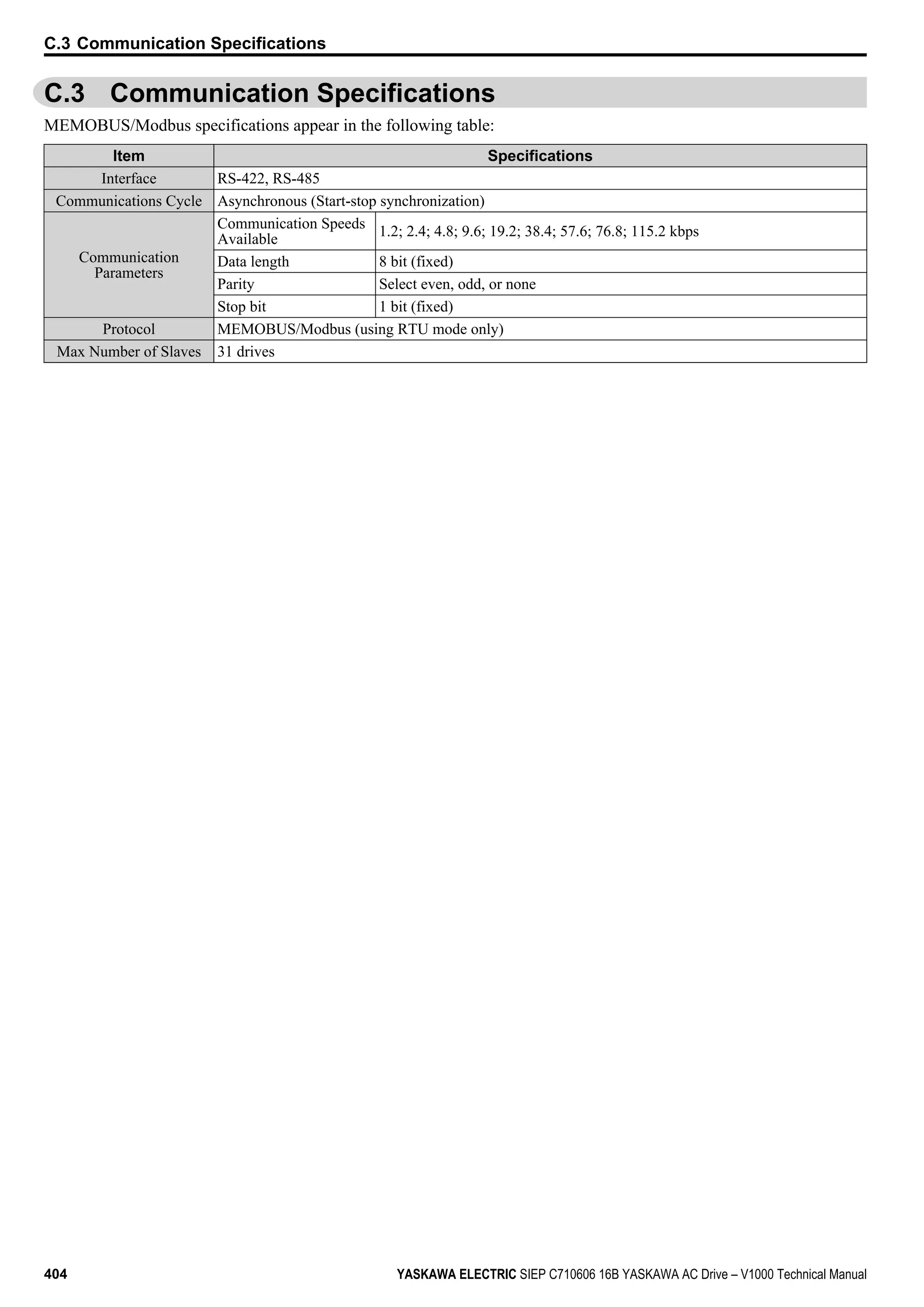
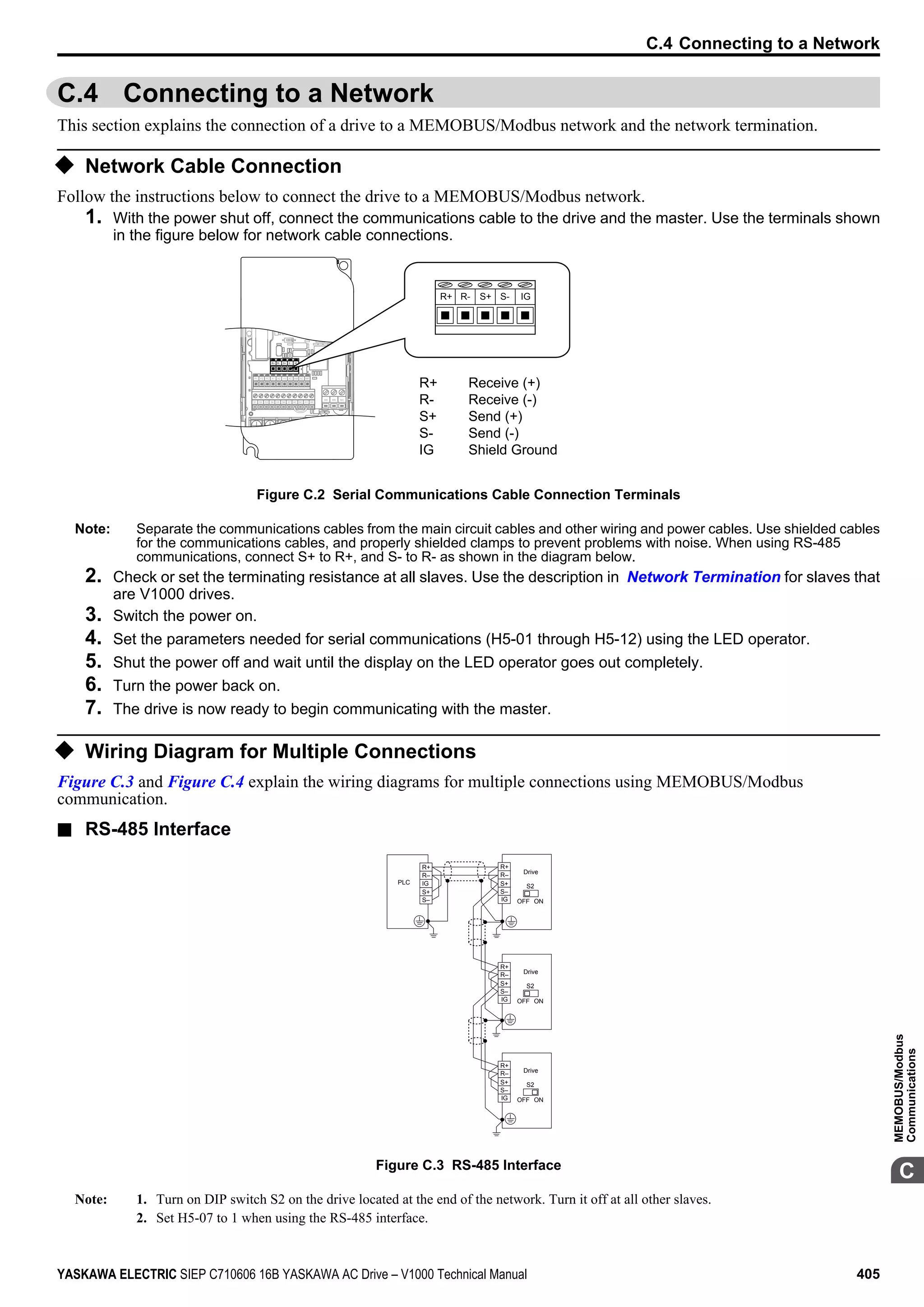


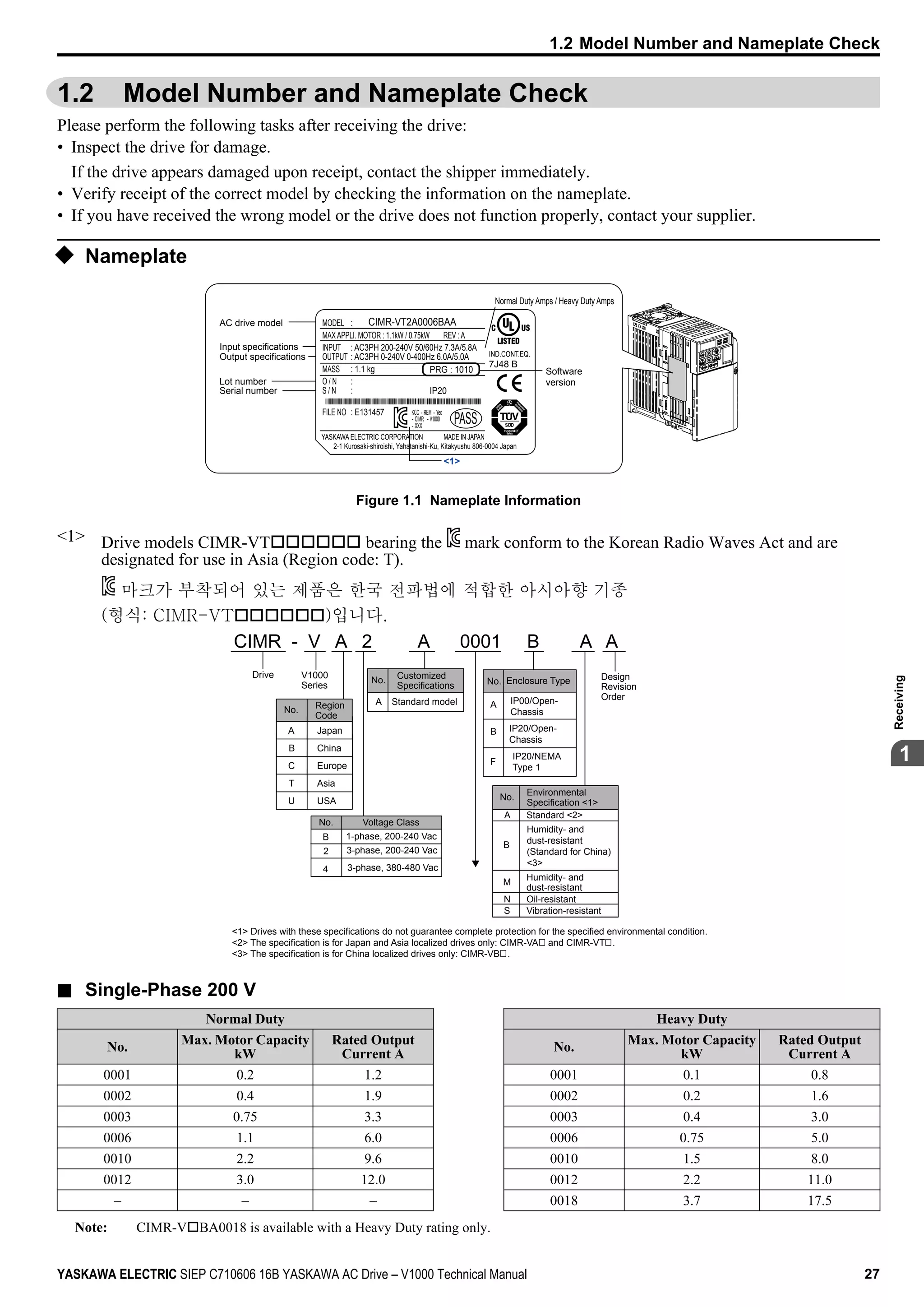
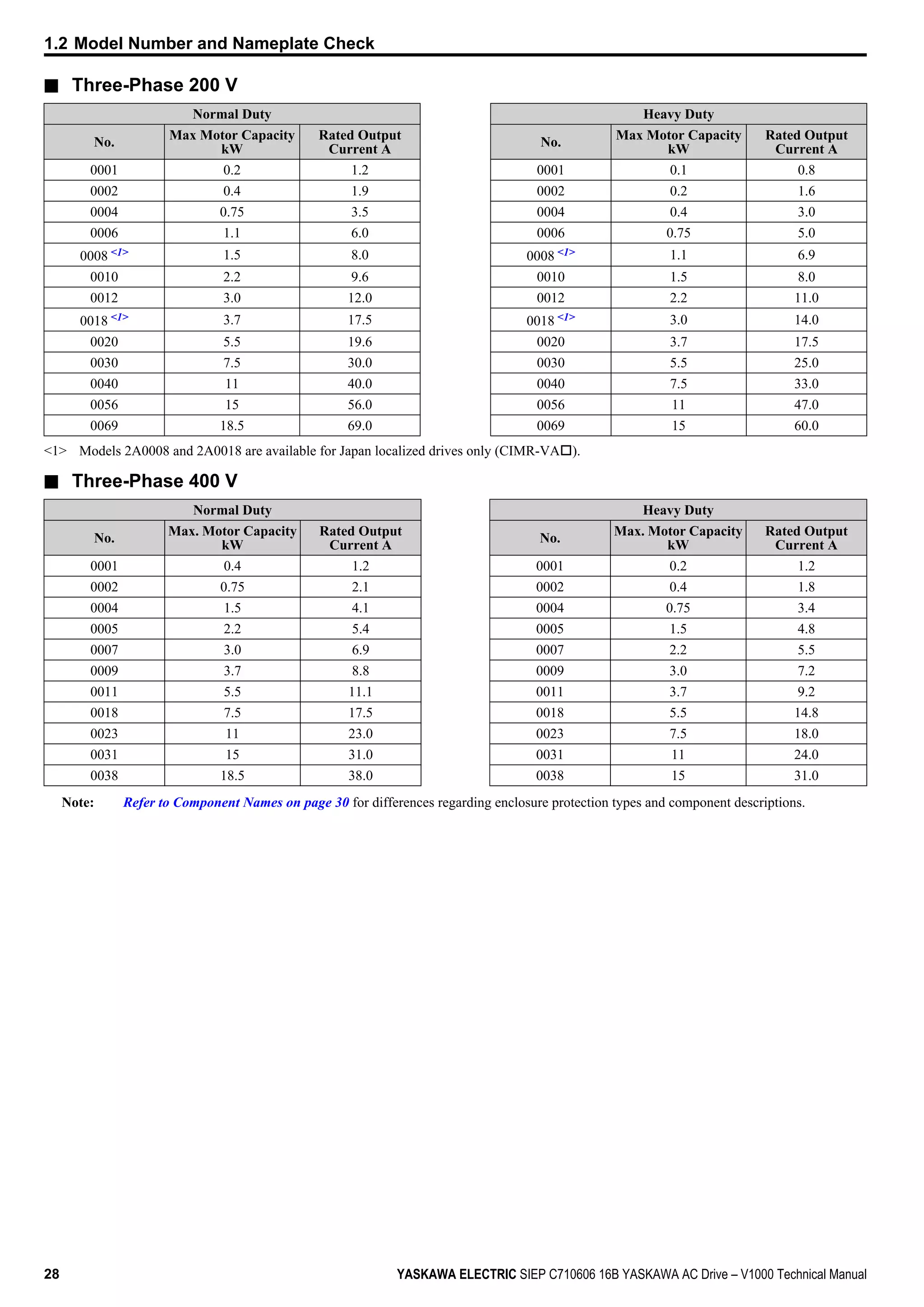
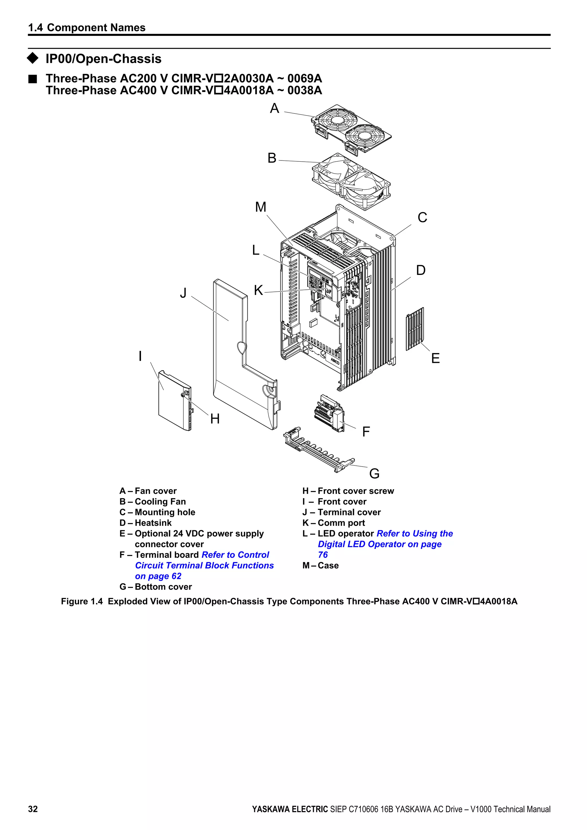
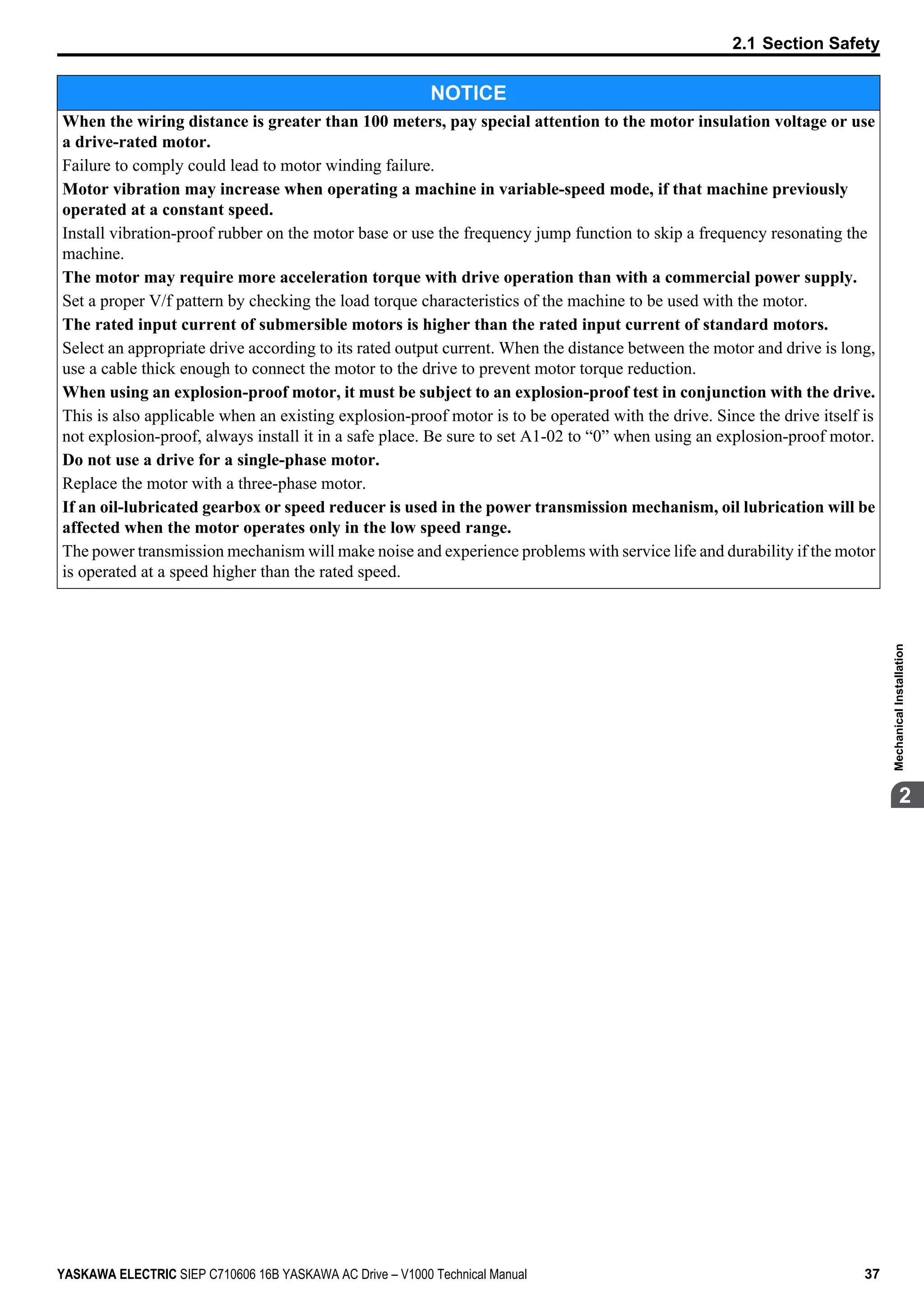
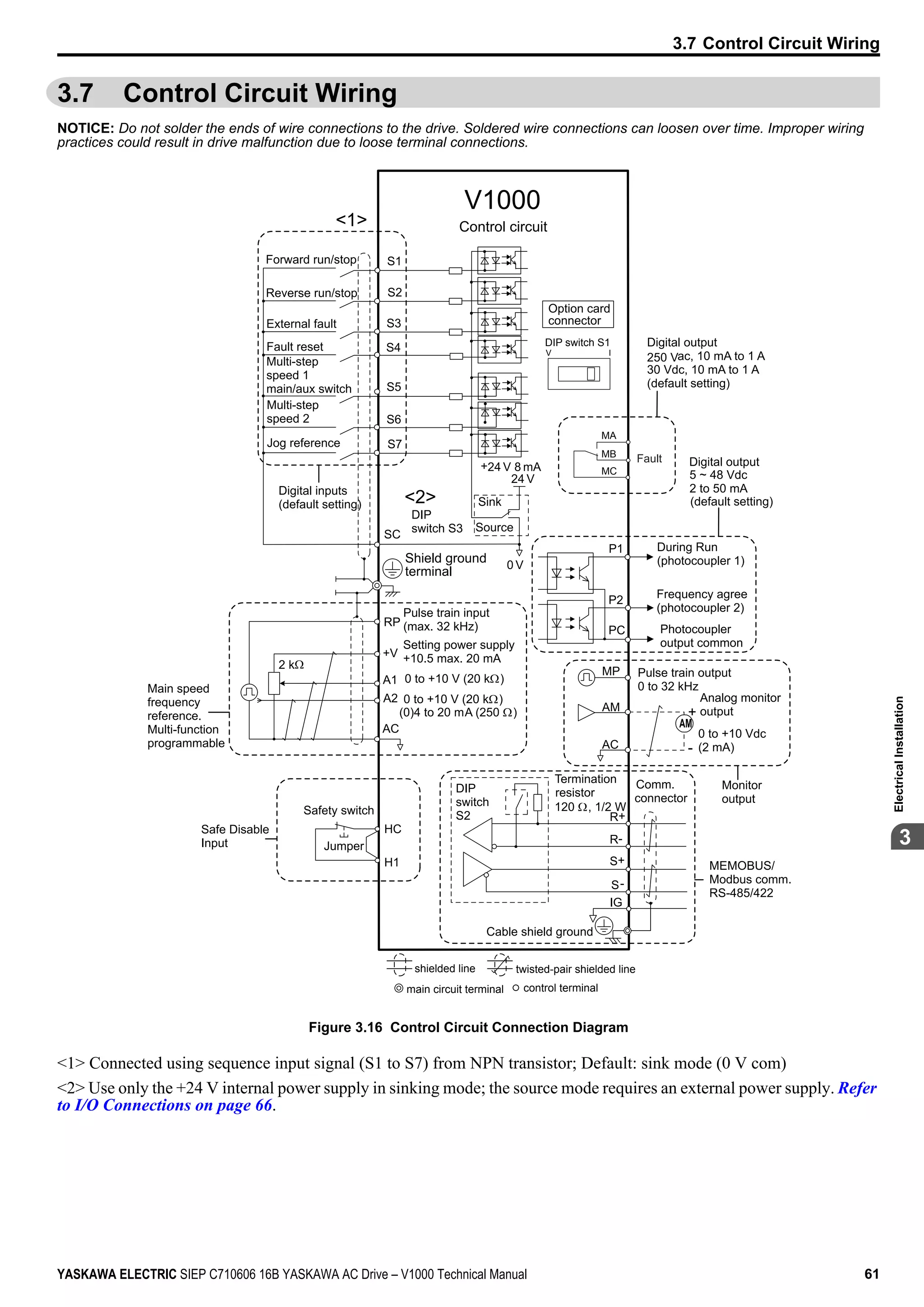
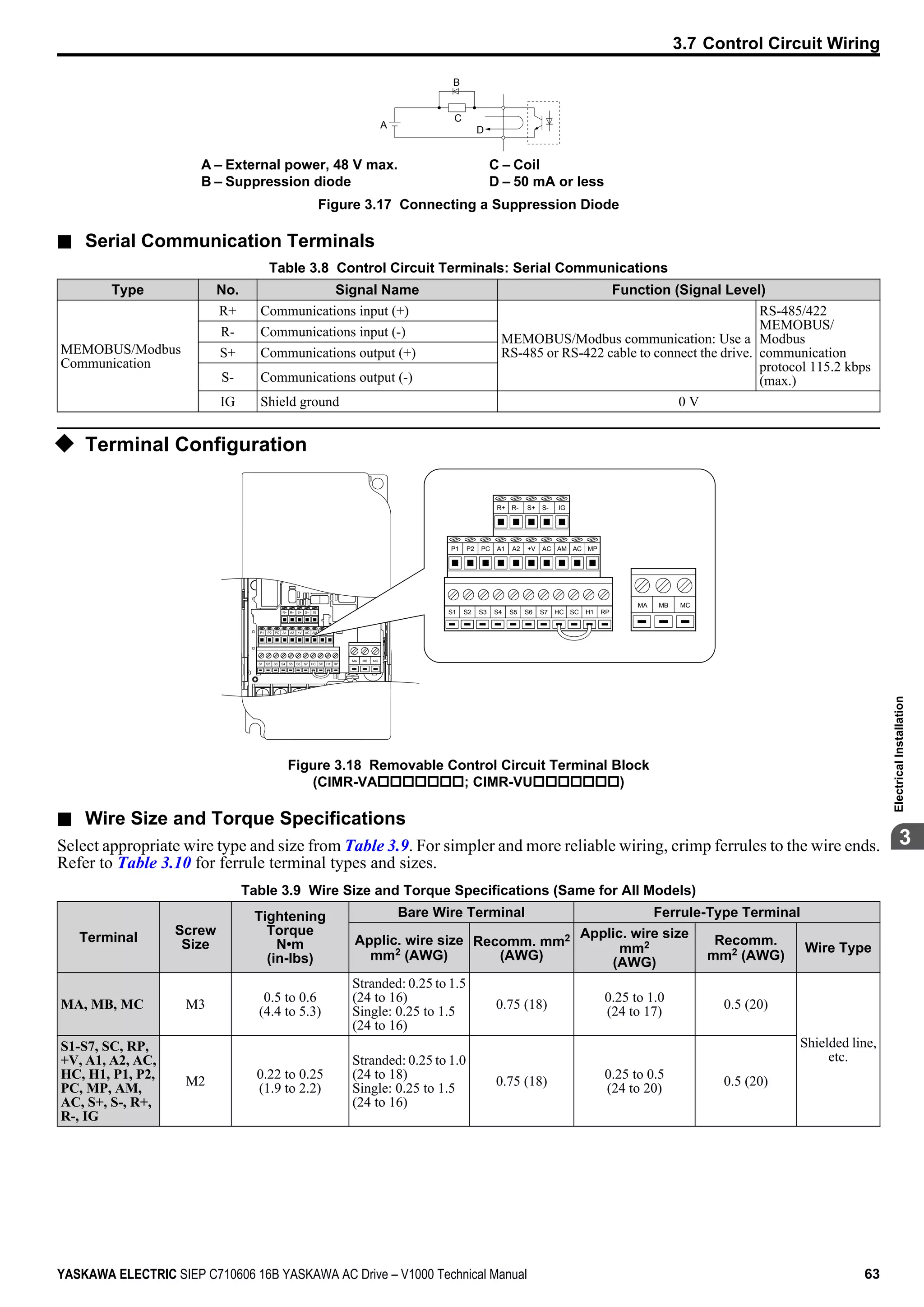
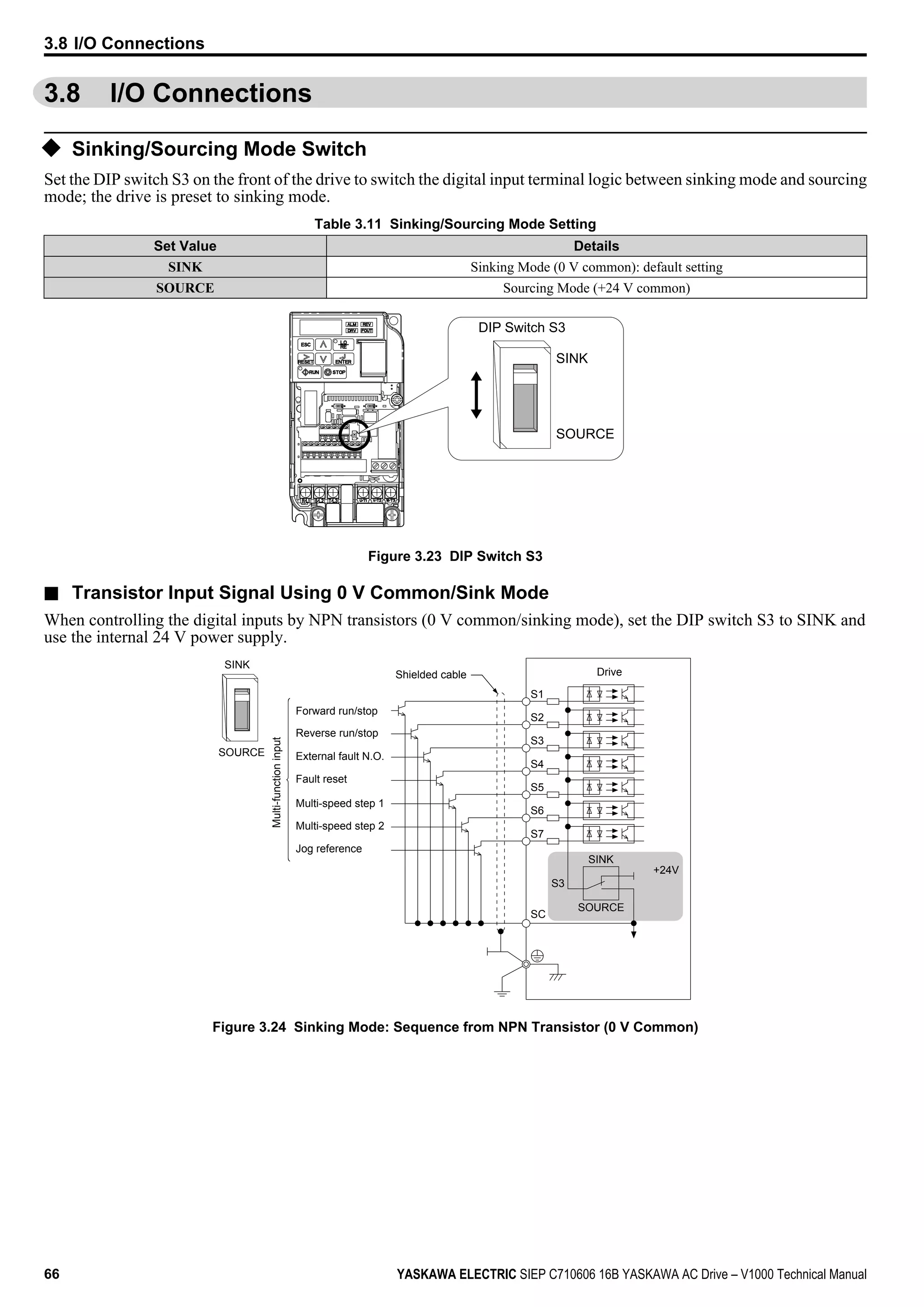
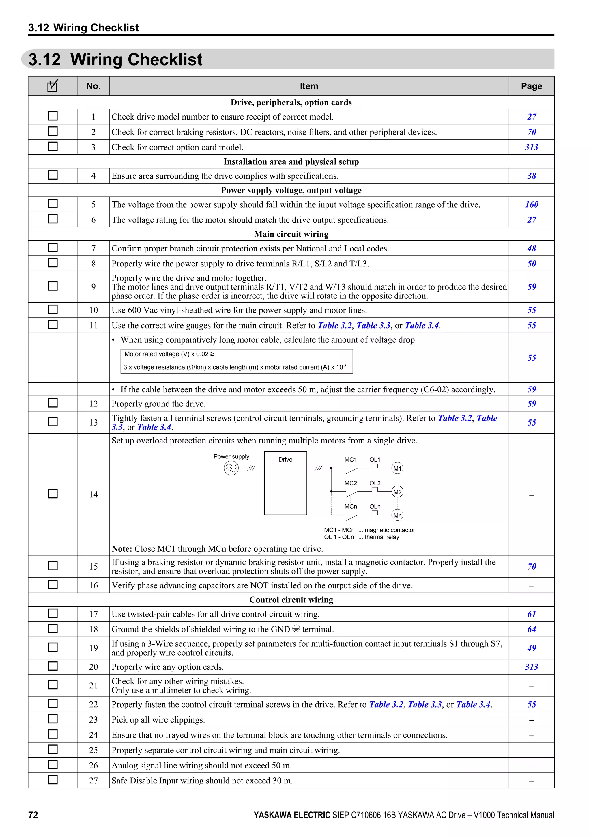
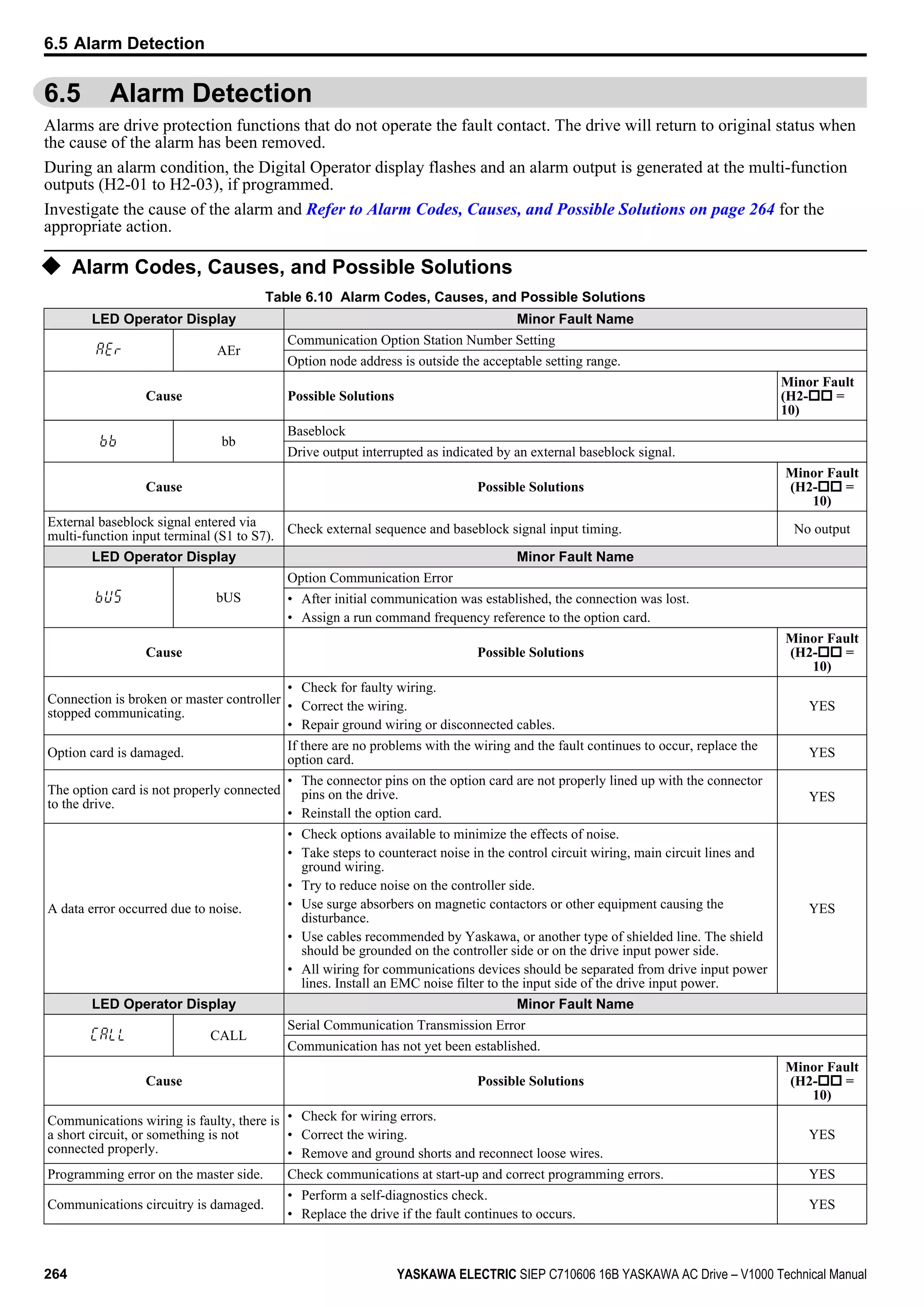
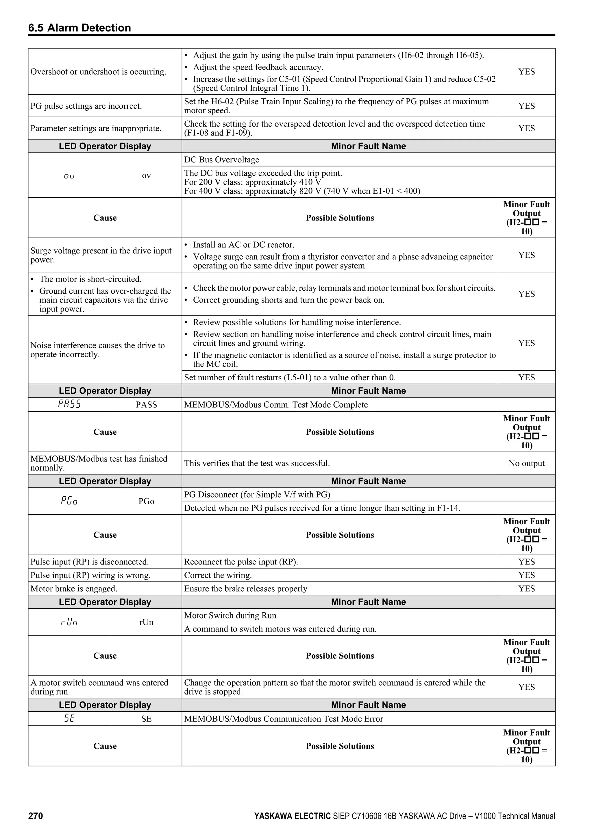
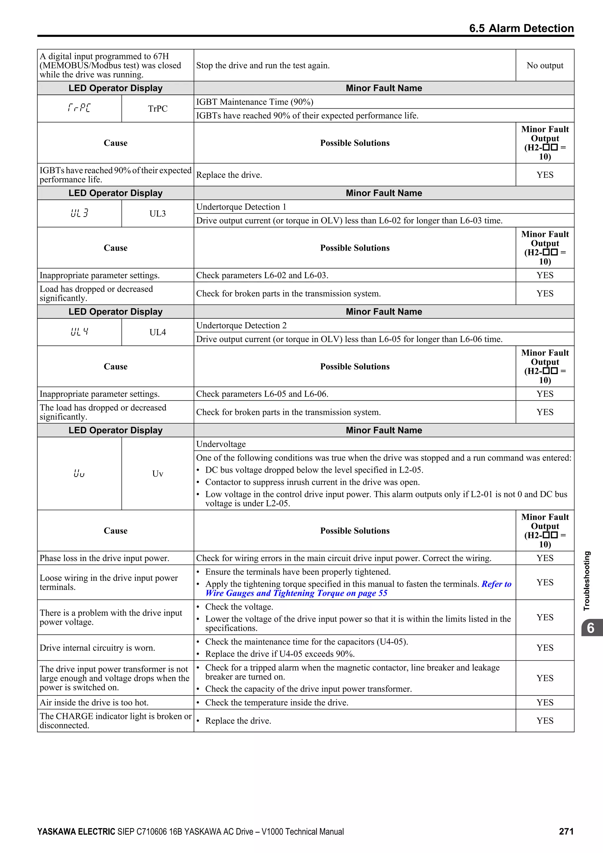
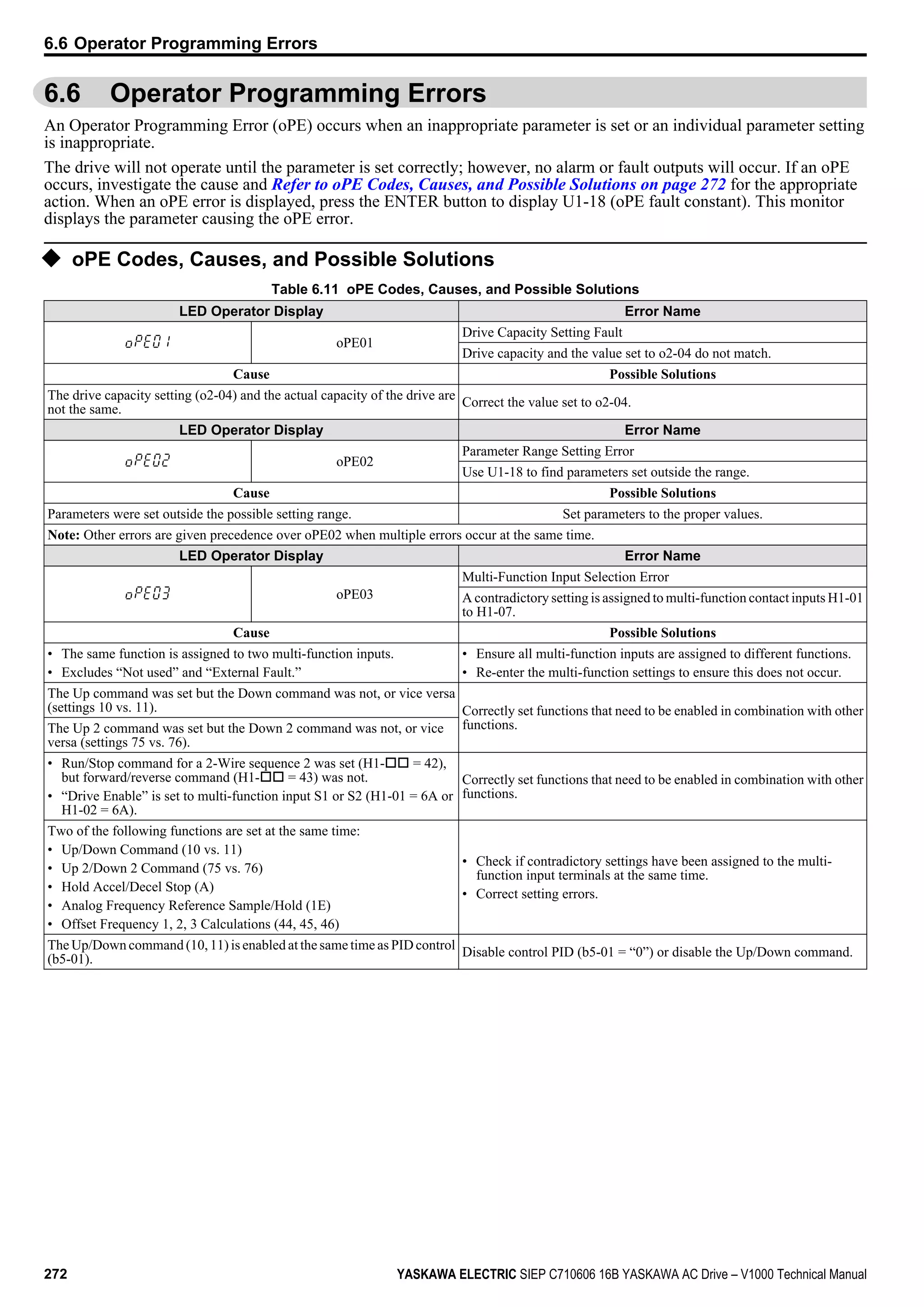
This document is a technical manual for Yaskawa AC Drive V1000 variable frequency drives. It provides installation and operation instructions for drive models in the 200V and 400V classes with power ratings from 0.1 to 18.5kW. The manual contains sections on receiving, mechanical installation, electrical installation, start-up, programming, troubleshooting, maintenance, specifications and other reference information. Safety notices and precautions for proper use are provided throughout.